DARAY X210 LED Manual

X210 LED
Examination Light
Operating & Installation Manual
QAM.X210.0818.10
X210LW

Page 1of 20

Page 2of 20
Table of Contents
1. Introduction ................................................................................... 3
1.1 Supported Lights......................................................................... 4
1.2 Technical Drawings...................................................................... 5
2. Technical Specifications..................................................................... 7
2.1 Serial Numbers and Labelling .......................................................... 8
3. Operation...................................................................................... 8
4. Correct Usage................................................................................10
5. Installation ...................................................................................11
5.1 X210LW Standard Wall Mounted version.............................................11
5.2 X210LE Wall Mounted version (flush-fit).............................................12
5.3 X210LR Rail Mounted version..........................................................13
6. Fuse Replacement...........................................................................14
7. Maintenance .................................................................................15
7.1 Maintenance Schedule .................................................................15
7.2 Routine Maintenance...................................................................15
7.3 Product cleaning & care guidelines ..................................................16
7.4 Safety Precautions......................................................................17
8. Spare Parts ...................................................................................17
9. Warranty Information.......................................................................18
9.1 Returns Policy ...........................................................................18
9.2 Warranty Details ........................................................................19

Page 3of 20
1. Introduction
DARAY’s X210 LED is a state-of-the art, cost-effective examination light for use during
medical or veterinary consultation and diagnosis. The light uses the latest LED technology
to give an intense light at the ideal colour temperature for accurate medical diagnosis
(without the need for secondary filtering) with virtually no heat. Wall and rail mounted
versions are available.
The X210 LED features a high output-intensity which is variable via an electronic dimmer
control located on the rear of the head. This control also acts as an on/off switch. The
light operates from a safe low voltage produced by a built-in mains transformer, and has a
swivelling and flexible arm and a rotating head to allow accurate and stable positioning of
the light-patch.
All painted surfaces of the X210 LED contain DARAY’s BioProtect™, an antimicrobial
protection against bacteria such as MRSA.
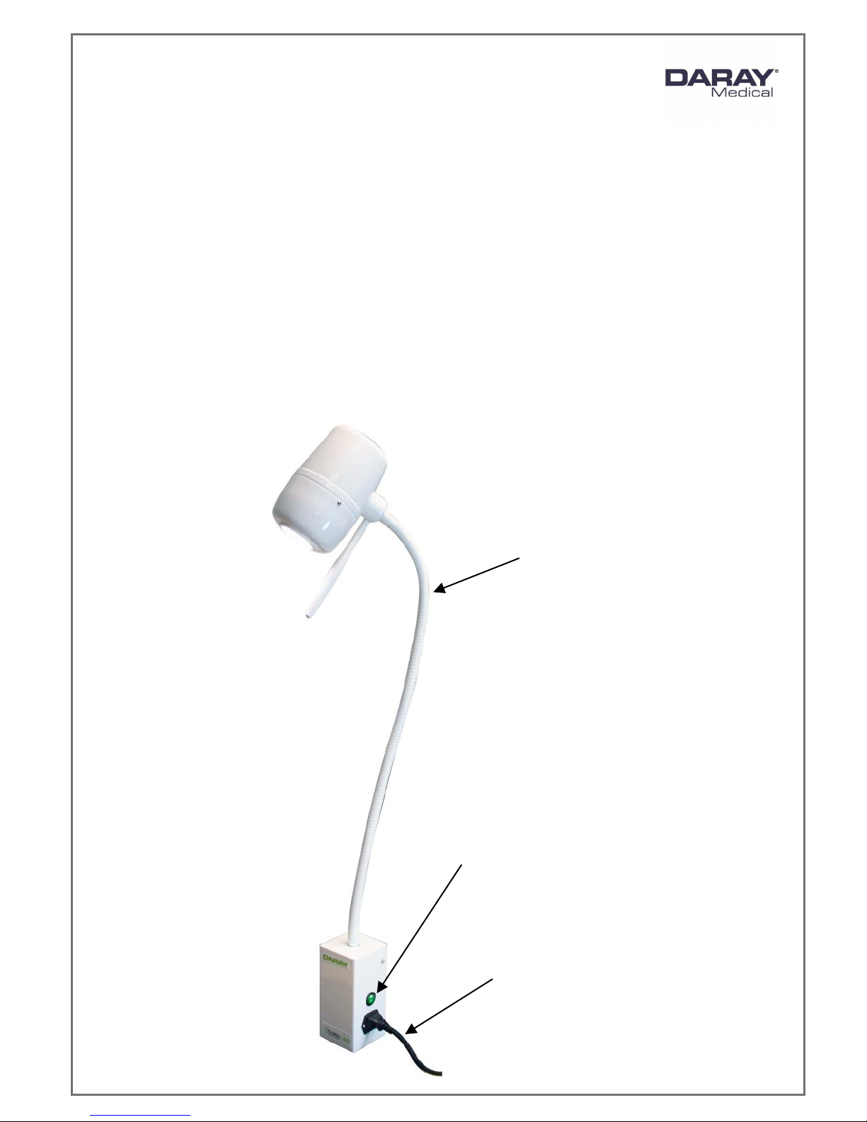
The light comprises 4 parts: light-head, flexible arm, power-supply module (integrated
into mounting box), and the mounting box itself. If you have purchased the standard wall
version or the rail mounted version, you will also have an IEC cable (X210LW & X210LR).
The flexible arm allows the light-patch to be placed accurately and stably where it is
needed. The arm is covered with a PVC sleeve to prevent contamination and allowing easy
cleaning. The power-supply module contains an electronic transformer to provide a low
voltage to power the light from a mains input.
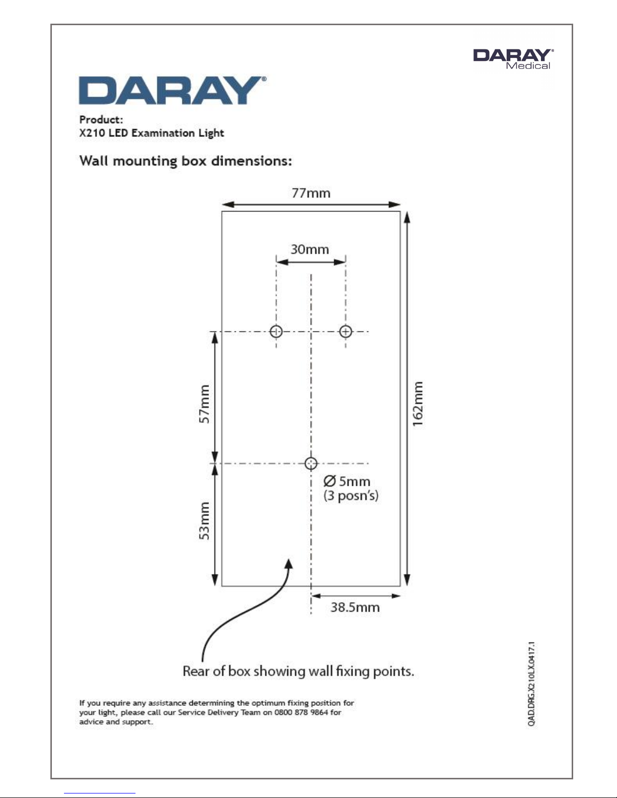
The integral back-plate wall mounting provides a simple method of fixing the light to the
wall. When mounted, no fixings are visible. The power-supply module can be wall-
mounted with chased-in cabling fed into the rear (X210LE), or by a side-mounted IEC inlet
and a flex with moulded plugs (X210LW). The rail-mount version (X210LR) features a
clamp to fasten the light to a standard medical equipment rail. DARAY can also supply
medical rail in 1m lengths.
All versions are delivered in special-to-type packaging which identifies on the ends of the
box the model type and serial number of the light within.
This user & installation guide contains all the information you need for installation,
operation and maintenance.

Page 4of 20
For further information on our product range and find out more about our company please
visit www.daray.co.uk or call 0333 321 0971 or 0800 804 8384.
This product was designed & manufactured in Great Britain by:
Daray Ltd.
Edison House,
Robian Way
Swadlincote
Derbyshire
DE11 9DH
1.1 Supported Lights
The Following Models are supported in this Manual
X210LW
X210 LED Wall Mounted Examination Light –with IEC cable
X210LE
X210 LED Wall Mounted Examination Light –Electricians fit
(flush-fit
X210LR
X210 LED Rail Mounted Examination Light –with curled IEC
cable (rail sold separately –part code XRAIL)

Page 5of 20
1.2 Technical Drawings

Page 6of 20

Page 7of 20
2. Technical Specifications
Light Source
LED
Light Intensity (Lux) @ 0.5m
32,000 Lux ±5%
Light Intensity (Lux) @ 0.75m
14,000 Lux ±5%
Light Intensity (Lux) @ 1.0m
8,000 Lux ±5%
Light Intensity Adjustment Range
10 - 100%
Colour Temperature (Kelvin)
4,300K ±500
Colour Rendering Index (CRI)
95
Colour Rendering (R9)
88
Light Field Diameter (D50)
@ 0.5m: 120mm
@ 0.75m: 135mm
@ 1.0m: 180mm
Light Field Diameter (D10)
@ 0.5m: 230mm
@ 0.75m: 325mm
@ 1.0m: 460mm
Number of LED’s
3
Power Consumption
12W 0.1A
Average Working Life
>50,000 Hours
Input Voltage
100 - 240V AC 50/60 Hz
Output Voltage
12V DC 1A
Temperature Rise on Patient/User
≤2°C
Warranty Period
5 Years
NHS E-Class Code
FBU, FKR
Commodity Code
9018 908400
GMDN Code
12276

Page 8of 20
2.1 Serial Numbers and Labelling
Each X210 LED is allocated a unique serial number located inside the wall mounting box.
The power-supply module carries its own identification and serial number.
3. Operation
1. Switch the power ON via the mains socket. If you have the X210LE hard-wired version
and you have wired the light to a switch on the wall, ensure you locate the correct
switch.
2. Press the switch on the side of the wall mounting box. The mains indicator is
illuminated green once powered on.
If the mains indicator does not illuminate, check the mains supply and then the fuses
in the module which are located on its right-hand side. For models powered via an
IEC lead with a moulded mains plug, check the fuse in the mains plug.
3. Operate the light using the push-button controller on the rear of the light head. This
is a momentary-type switch and does not latch.
Press the switch once to turn the light ON
Press and hold to decrease intensity*
Press and hold to increase intensity*
Press the switch once again to turn the light OFF
*You can notice visually once the light has reached the end of its intensity range.
Light-head
handle
Push-button controller

Page 9of 20
Note: If mains power is removed, the intensity will be reset to its brightest setting when
mains power is restored.
Note: Unplug the power supply if the light is not going to be used for extended periods.
The light-head swivels on its mounting flexible arm, and the flexible arm itself also swivels
where it fits into its mounting. This rotation and the flexible arm itself allow the light patch to
be placed where you want it.
The light-head itself can rotate 320° around the flexible arm.
Use the handle to steer the light-patch to where you want it; in the interests of cross-infection
control, avoid touching any other part of the light.
After use, switch off at the light-head switch and also, where applicable, at the power-
supply module on the wall.
Flexible
arm
Green illuminated mains
power switch
IEC cable: present on
X210LW and X210LR

Page 10 of 20
4. Correct Usage
Caution MUST to be taken to ensure correct usage of the light, to preserve all features –in
particular the flexible neck (‘gooseneck’)
If you need to bend the neck to reposition the light head, keep one hand approximately one
third up the neck, and then use your other hand to curve the gooseneck through its entire
range, avoiding sharp kinks that will cause irreparable damage.
Try to avoid bending the neck by pushing and pulling the light head with one hand, as it will
inevitably cause undue stress on the base of the neck, and will subsequently reduce the ability
of the neck to hold itself in position.
We strongly advise that all staff members reading this manual adequately train all other staff
members who may be using this light.
Common sense must prevail at all times.

Page 11 of 20
5. Installation
5.1 X210LW Standard Wall Mounted version
CAUTION: This product must be earthed.
Check you have the following items:
X210 LED Light –supplied complete with mounting box/PSU
IEC Cable
Kit including user manual and hex key
WARNING: please note that this information is provided for guidance only and that a
qualified builder or structural engineer should be consulted if you have any doubt about the
suitability of the proposed mounting position.
Note: For all wall mounted and rail mounted installations the recommended fixing height is 1000
-1300mm from the floor. The flexible neck works under tension and should be installed in an
upright position. Please refer to the dimensional drawing located on page 5 of this manual
when determining the mounting position. For any installations requiring a different fixing
height please contact DARAY for advice on 0800 878 9864.
Mounting the box to the wall:
Remove the 4 cover screws with the hex wrench provided
Release the earth bond from the back-plate by removing the nut and
shake-proof washer
Using the back-plate as a template, mark its position on the wall, bearing in mind the
final position of the light-head. Fixing point dimensions on page 6 of this manual
Fix the bracket to the wall
Whilst supporting the weight of the power
supply module and light, replace the earth
bond to the back-plate with the shake-proof
washer and nut
Fit the power supply module to the wall
bracket with the 4 cover screws
Connect the IEC flex to the socket on the
side of the power supply module
Plug the IEC flex into a 13A mains socket
and check for correct operation

Page 12 of 20
Terminal block
Non-slip washer
Nut
5.2 X210LE Wall Mounted version (flush-fit)
CAUTION: This product must be earthed.
Check you have the following items:
X210 LED Light –supplied complete with mounting box/PSU
Kit including user manual and hex key
Note the mounting position advice and warnings offered on page 13 of this manual.
Flush-fitting the wall box (chased-in cables):
Remove the 4 cover screws from the wall mounting box with the hex wrench provided
Feed the mains supply via the cable entry hole on the back plate
Connect the mains supply to the fused terminal block found on the back plate
Using the back-plate as a template, mark
its position on the wall, bearing in mind
the final position of the light-head.
Fixing point dimensions on page 6 of
this manual
Fix the bracket to the wall
Fit the power supply module to
the wall bracket with the
4 cover screws
Switch the power on
and check for correct
operation

Page 13 of 20
5.3 X210LR Rail Mounted version
Check you have the following items:
X210 LED Light –supplied complete with mounting box/PSU
X210 Rail Mount Kit accessory
Kit including user manual and hex key
NOTE: Rail not supplied –if required, order code XRAIL
If you are installing the XRAIL:
Hold the rail against the selected location on the wall, bearing in mind the final position
and range of travel of the light-head required, to project its light patch where it will be
needed.
Ensuring the rail is horizontal; drill the required fixing positions for 2 screw holes.
Fix the rail to the wall, using appropriate fixings if necessary and the 2 screws provided.
NOTE: Make sure you are aware of any hidden services in the wall.
Ensure the rail end caps and cover infill are properly fitted.
The rail mount clamp should already be fitted to the power supply module.
If upgrading; Screw the rail mount clamp to the rear of the wall mounting box
with the screws supplied.
Slacken sufficiently the light clamp to allow the clamp to pass over
the rail and fit the light to the rail.
Finger tighten the two retainer screws located
underneath the clamp to ensure clamp cannot
come off the rail inadvertently.
The light can be moved along the rail
by slackening the clamp slightly and
not sufficiently to allow the light to
become detached from the rail.
Connect the IEC flex to the socket on
the side of the power supply module.
Plug the IEC flex into a 13A mains socket
and check for correct operation.

Page 14 of 20
6. Fuse Replacement
CAUTION: Fuses normally blow for a reason. Investigate likely faults before changing fuses.
CAUTION: Isolate the unit from the mains before accessing the fuses.
Both the live and neutral mains inputs are fused. The fuses are contained in a holder which is
part of the IEC inlet mounted on the rear panel of the mobile base.
Unplug and remove IEC cable. Using a flat-bladed screwdriver, or similar, pull forward the
‘drawer’ containing the fuses. Hinge down the front of the holder. Lift the fuses by pushing
them through the holes below.
Refit new fuses (D10873) and reverse the removal sequence, ensuring the ‘drawer’ is
pushed fully home.
The above guidance applies only to X210LW and X210LR versions.
Warning: Ensure you isolate the unit from the mains power before any
work related to the electrical supply.
'Drawer'

Page 15 of 20
7. Maintenance
The proposed maintenance is only a suggestion. Depending on the use of the product
and the operating environment, this may need to be revised more often.
DO NOT ATTEMPT ANY FIXES BEFORE CONSULTING DARAY.
If you cannot resolve a problem then please contact our helpline on 0800 878 9864
7.1 Maintenance Schedule
Weekly checks
should include:-
Range of movement testing, it should be light and easy to move
throughout the range.
No visible signs of excessive wear.
Six monthly
checks to
include:-
Check all electrical connections are sound and that there is no
visible cable wear.
All fixings to be checked and be of sound construction.
7.2 Routine Maintenance
The X210 is designed and manufactured to stringent quality standards. Observing the following
procedures will help to maintain the light’s optimum performance:
-Light-head
Clean all exterior surfaces as required, consult section 7.3 for guidance.
-Flexible arm
Clean all exterior surfaces as required using the directions above.
If a kink is noticed in the arm, and is affecting the movement of the light, see section
5. Correct Usage, on page 12 of this manual.
-Wall/Rail Mount
Check for security fixing of wall bracket/rail to wall structure. We advise that this is
looked at annually. If there is any looseness of the fitting to the wall, we advise that
you cease use of the light immediately and consult your building
contractor/installer/maintenance staff.

Page 16 of 20
7.3 Product cleaning & care guidelines
The X200 Range features BioProtect® antimicrobial coating on all painted surfaces and has a
fully-enclosed head with an Ingress Protection (IP) rating of 54.
These guidelines are provided to help you maintain your equipment properly and prevent any
damage. Use of incompatible cleaning chemicals can adversely affect the finish and physically
damage the metal and plastic parts of the DARAY product, invalidating its warranty.
Please ensure these instructions are passed to the persons responsible for cleaning and they are
followed before each use.
Manufacturers recommended cleaning method:
1. Turn off the power to the light, and where possible, unplug the mains socket.
2. Remove noticeable contamination. Pay special attention to the light head and handle.
3. Ensure the equipment is surface-cleaned and disinfected using an appropriate, non-
abrasive cleaning agent (see recommended list below).
4. Dry all surfaces thoroughly with a clean cloth and check for damaged surfaces,
discolouration and/or contamination.
NOTE: Some DARAY products feature our BioProtect® antimicrobial coating on painted finishes.
This is designed to assist with infection control and is not a replacement for cleaning.
CAUTION: Our products are NOT waterproof. The equipment and accessories (included chargers
and battery packs) MUST NOT at any point be saturated, to prevent water ingress. Use a damp
cloth or saturated wipe if necessary. All electrical safety guidelines should be followed.
Any damage caused as a result of not following these guidelines will void any product warranty.
Below is a partial list of recommended surface agents:
Cavicide™ products
Isopropyl alcohol-based cleaners (<40% alcohol)
Ethyl alcohol-based cleaners (<40% alcohol)
Lysol® disinfectant
Other non-bleach and non-abrasive disinfectants or cleaners
DO NOT USE agents containing the following:
Organic, mineral and oxidizing acids (min. pH value 8.5)
Bases (max. acceptable pH value 8.5)
Oxidation agents (e.g. Hydrogen Peroxide)
Halogens (chlorine, iodine, bromide)
Aromatic/halogenized hydrocarbons
Bleach-based cleaners (e.g. Clorox™, Sterilox™)
Abrasive cleaners (e.g. Comet Cleaner™)
Acetone-based cleaners (e.g. nail polish remover, Goo-off™)
MEK (Methyl Ethyl Ketone)
If you are unsure whether you are using the correct cleaning fluids on your DARAY equipment,
please feel free to get in touch with us for advice.

Page 17 of 20
7.4 Safety Precautions
For all cleaning work, power off the equipment and where possible unplug
the mains socket, only minimal cleaning fluids should be used.
Please do not look directly into the light source when illuminated.
If the equipment is dented or scratched this should not impact the usability
of our lights however we advise that if the BioProtect® coating is damaged
and the metal casing underneath is visible, please do not attempt to ‘paint’
over it as this will impact upon the effectiveness of the coating, simply use
an alcohol based cleaning spray when cleaning and pay special attention to
the cut.
If there is damage to the power cable or if exposed wire is visible
DO NOT USE
8. Spare Parts
CAUTION: Use only genuine ‘DARAY’ replacement lamps as other types may seriously impair the
optical performance of the product.
ITEM NO
PART NAME
TYPE
PART NO
1
Fuse
1A 20mm
D10873
2
Microfibre cloth
5 pack
DRK4080
4
Replacement Handle
White
D15194
6
30V 1A LED Transformer Module
30V 1A
D15081
All of the above parts can be purchased via DARAY
For any SPARE PARTS or TECHNICAL ISSUES phone DARAY’S Service Delivery Team on:
+44 (0) 800 878 9864
Opening times 9am–5pm Monday to Thursday (excluding bank holidays)
9am-2:30pm on Friday
Or email:
IF THE LIGHT WAS ORIGINALLY PURCHASED THROUGH A DISTRIBUTOR CONTACT THEM IN
THE FIRST INSTANCE FOR A RESOLUTION
Please contact DARAY for help with any problems that the distributor cannot solve.

Page 18 of 20
9. Warranty Information
9.1 Returns Policy
DARAY's standard warranty is 12 months. However, this period may be extended for this product to
5 years free of charge, simply by completing and submitting the warranty registration online.
We want you to be completely satisfied with your purchase. If you need to return goods purchased from
DARAY Ltd, please read the following information carefully.
The DARAY Ltd returns policy provides guidance on when you can return goods we have supplied, and what
you can expect from us once you do. To see our detailed returns policy and procedure visit
www.daray.co.uk/returns
TYPE OF RETURN
REMEDY
DAMAGED GOODS
Goods which are physically damaged on delivery
We must be notified within 24 hours of receipt.
Dead On Arrival (DOA)
Goods which do not work
Goods which do not work on arrival or develop a fault
within 28 days, we will advance replace the item.
GOODS DEVELOPING A FAULT
Goods which have developed a fault within the
warranty period.
If the fault develops after 28 days, but within the warranty
period, we will initiate the returns procedure.
NON WARRANTY
Goods which have developed a fault outside the
warranty period.
If a fault develops outside the warranty period, we will
initiate the returns procedure charges may be applicable.
OTHER
Any situation which is not covered by any of the
above.
We will always try to help, but we cannot normally offer a
refund.
For additional clarification, please refer to our terms and conditions at www.daray.co.uk/terms.
In a small number of cases, we may determine that a replacement would not work any better than the
original product we supplied. In such cases we will only offer a refund rather than a replacement for
qualifying returns.
Replacement bulbs and spare parts ordered on our website or from supplied part codes are not eligible
for credit. We will accept returns and exchange for the correct item.
If your purchase an item incorrectly you can return it within 14 days and it can be exchanged for another
product of equal or higher value, excluding transportation charges incurred. Goods and packaging must be
returned in their original condition. Under no circumstances will goods be accepted for return if they are
damaged, have been subjected to improper handling or abuse or have been used.
If you send us goods that do not qualify for return, you will invalidate your claim to any refund, and you
will be obliged to compensate DARAY Ltd for the cost of return postage and any other reasonable costs
incurred processing the goods.
Your statutory rights are not affected.
IMPORTANT!
Please fill out your warranty registration online at
www.daray.co.uk/warranty or contact DARAY by phone (0800 878
9864) or email [email protected].uk
Year 1: Warranty includes parts and labour
(Return to Base)
Years 2-5: Parts only
*UK only

Page 19 of 20
9.2 Warranty Details
TERMS AND CONDITIONS OF WARRANTY
1. To qualify for this warranty you must register on www.daray.co.uk or return to Daray Ltd (Daray) the
duly completed warranty-registration form accompanying the product.
2. Daray warrants this product (excluding lamp) against faulty material and workmanship during the
period of the warranty. The period of warranty is the period stated on your warranty card and
commences on the date of purchase of the product. In the event that the product is not in good
working order Daray will provide, during the warranty period, a free repair service within the United
Kingdom. The warranty is subject to proof of purchase being provided; therefore, you should retain
your original receipt.
2.1 The repair service consists of the provision of spare parts and/or replacement products (at Daray’s
discretion) which will be provided on an exchange basis and will either be new, equivalent to new
or reconditioned. All replaced spare parts and products shall become the property of Daray.
2.2 Daray’s only obligation under this warranty is the provision of the service as set out above.
2.3 All products are returned to Daray at the customer’s cost and risk. Products to be returned should
be adequately packed. For the address to send returns to please visit www.daray.co.uk
3. Daray’s arrangements for providing service provided under this warranty may include the use of sub-
contractors.
4. This warranty does not cover damage or defects in the Product caused by or resulting from:
Wilful neglect or negligence by anyone other than Daray;
Improper use, storage or handling of the product;
Use of non-Daray approved parts (such as replacement lamps) not compatible with the
Product;
Fire, accident or disaster;
Use of non-Daray modifications other than in accordance with Daray’s instructions;
Attachment of fittings and accessories not approved by Daray;
Repairs, modifications carried out by service personnel not approved by Daray;
Damage caused by chemical corrosion from cleaning agents not approved by Daray.
Failure to use or install the product in accordance with the manufacturer’s instructions.
5. Nothing in this warranty shall have the effect of restricting or excluding the liability of Daray in respect of:
a) Death and personal injury caused by the negligence of Daray, or for fraud;
b) Under the Consumer Protection Act 1987 to a person who has suffered damage caused by a
defective product or to a dependant or relative of such a person;
c) Direct damage to your property caused by the proven negligence of Daray.
6. This agreement does not give any rights other than those expressly set out above and in particular, Daray
will not be responsible for any loss of income, profits or contracts or any direct or indirect consequential
loss, damage caused to or suffered by the purchaser as a direct result of this agreement.
7. This warranty is offered (subject to these terms and conditions) in addition to, and does not affect
your statutory rights.
8. Daray may disclose your details and other personal information to companies within the Daray group
including any subsidiary company or sub-contractor of Daray for the purposes of performing our
obligations hereunder.
9. You must not resell outside the UK any products supplied by Daray and covered by the Export of
Goods (Control) Order 1992 (or any law that replaces it) without obtaining all necessary licences. You
also agree not to sell the product in the UK if you know or think that the person buying the product
intends to export it without getting the necessary licences. You agree to impose similar conditions to
these on anyone you sell the product to.
10. These conditions shall in all respect be governed and construed in accordance with English law and
the exclusive jurisdiction of the English courts.
Product:
Serial No:
Table of contents
Other DARAY Lighting Equipment manuals
Popular Lighting Equipment manuals by other brands

LITESHEET
LITESHEET BriteCor AC BWB installation manual

Pebble Grey
Pebble Grey Adonis installation instructions

A&A Manufacturing
A&A Manufacturing QuikDekClor Installation instructions & user guide

Excelitas Technologies
Excelitas Technologies XLED1 quick start guide

Safavieh
Safavieh TBL4292A quick start guide

Marq
Marq Gamut PAR H7 Service manual