Data East Maverick The Movie User manual

Cpu JUMPER TABLE
.: .:.:.:..:. G cpU:.'RoM: :jÜth,è s .
: :ROM _IJüers
. .. ame Position Instatled Removed _ :
Game . PoSlilon Installed Removed
01 LaserWar -i--- 5C J4J6aJ7a J5J6J7b 14. StrTrek 3 5C J5 J4
. _2__ 5B, 5C J4J5aJ6a J5J5bJ6b 15. Hook 3 5C J5 J4
fl2. Secret Service 2 5B, 5C J4 J5 16. Lethal Weapon 3 3 5C J5 J4
03. Torpedo Alley _î_ 5B, 5C J4 J5 17. StarWars 3 50 J5 J4
04. lime Machine 2 5B, 5C J4 J5 is. Rocky & Buliwinkle & Friends 3 5C J5 J4
05. Playboy _2__ 5B, 5C J4 J5 19. Jurassic Parl 3 5C J5 J4
06. ABC Monday Night Football 2 5B, 5C J4 J5 20. Lest Action Hero 3 5C J5 J4
07. Robocop _a_ 5B, 5C J4 J5 21. Tales from the Crypt 5C J5 J4
08. Phantom of the Opera 2 5B, 5C J4 J5 . The Whos Tommy 3 5C J5 J4
09. Back to the Future 3 5B, 5C J4 J5 23. WWF Royal Rumble 3 5C J5 J4
lo. The Simpsons 3 5B, 5C J4 J5 . Guns N' Roses 3 5C J5 J4
11. Checkpoint 3 5B, 5C J4 J5 s. Maverick 3 5C J5 J4
12. Teenape Mutant Ninja Turtles 3 5B, 5C J4 J5
13. Batman _a_ 5B, 5C J4 J5
Board Combinaons with ROM at Location 5C (Game i Verl) installed Jib, J3, J4, J6a, J7a & J8 Removed Jla, J2, J5, J6 & J7b
Bd. Combinations w/ ROM at Locations 5B, 5C (Game i , Ver2) installed Jib, J3, J4, J5a, J6a, J7b & J8 Removed Jia, J2, J5, J5b, J6b, & J7a
Bd. Combinations w/ ROM at Loc. 5B, 5C (Games 2-13, Ver2/3) Installed Jib, J3, J4, J5b, J6b, J7b & J8 Removed Jia, J2, J5, J5a, J6a & J7a
Bd. Combinations with ROM at Loc. 5C (Games 14-25, Ver3) Installed Jib, J3, J5, J5b, J6b, J7b & J8 Removed Jia, J2, J4, J5a, J6a & J7a
* Version i has a 2K RAM which is a 24-pin IC in Position 5D; Version 2/3 have a 8k RAM which is a 28-PIN IC in Position 5D.
Board Compatibility (Reflexive & Non-Reflexive) of CPU Boards
Version 1 and 2-Reflexive--Solenoid DriveTransistor is enabled directly bya switch closureon the solenoid assembly.
Version 3-Non-Reflexive-SolenoidDrive Transistoris enabled by the CPU after reading a switch closure in the Switch
Matrix. All CPU Boards are backwards compatible (e.g. Jurrasic Park I Vor. 3 to Time Machine I Ver. 2). Swapping a
Version 2 Board to a Version 3 is not possible dueto thespecial solenoids section (i.e. Slingshots, Turbo Bumpers, etc.)
changing from Reflexive to Non-Reflexive on Version 3 Boards.
Power-Up CPU Self Tests
Upon power-up, the CPU Board performs a series of selftests of major components. Turn the game on while observing
the LEDs on the CPU Board. Tests of the PIAs, RAM, and EPROMs are performed automatically and results of the
tests are indicated bythe PIA LED.
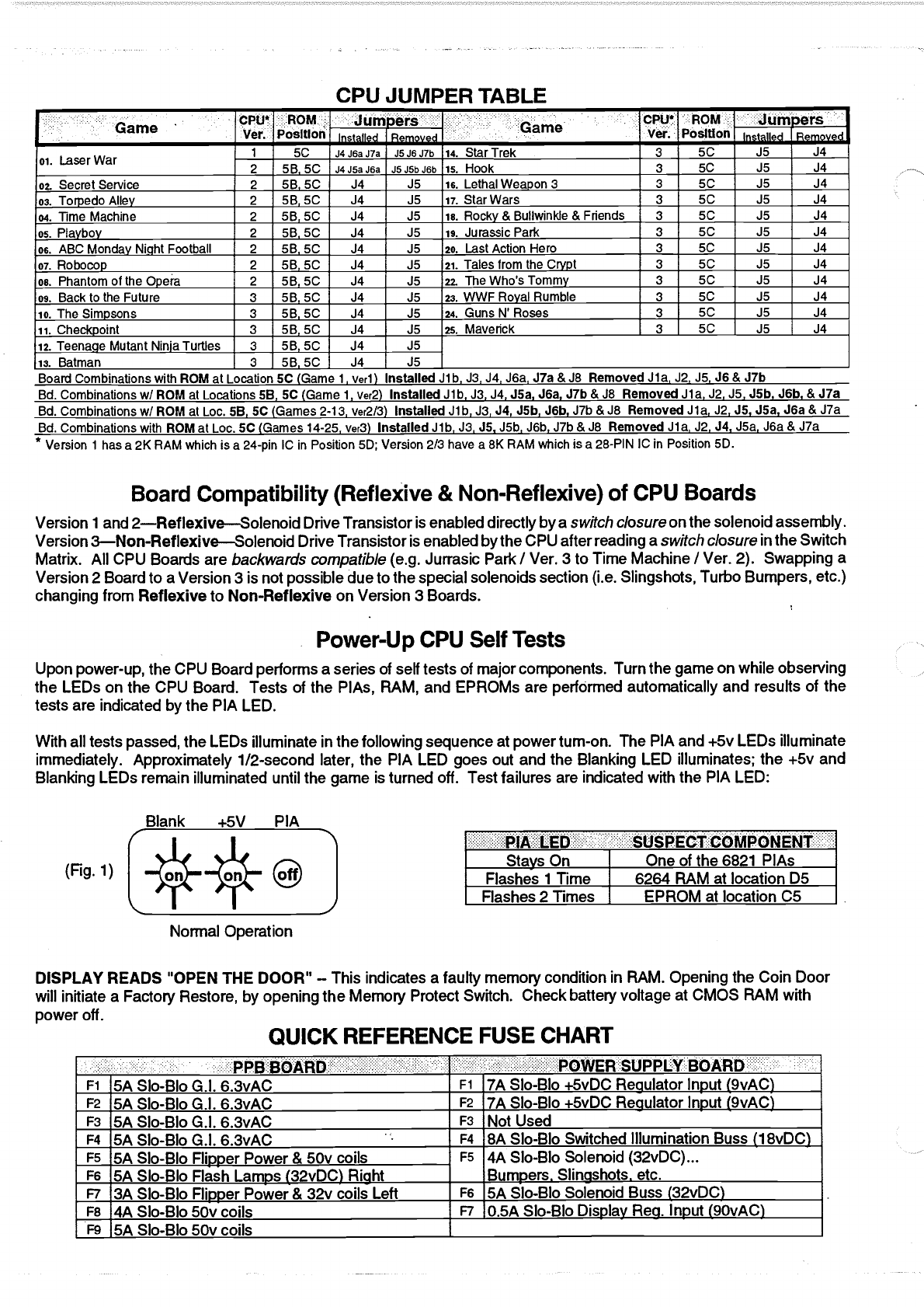
With all tests passed, the LEDs illuminate in the following sequence at powertum-on. The PIA and +5v LEDs illuminate
immediately. Approximately 1/2-second later, the PIA LED goes out and the Blanking LED illuminates; the +5v and
Blanking LEDs remain illuminated until the game is turned off. Test failures are indicated with the PIA LED:
Blank .4-5V PIA
(Fig.1) [:**@
Normal Operation
Stays On One of the6821 PIAs
Flashes i Time 6264 RAM at location D5
Flashes 2 Times EPROM at location C5
DISPLAY READS "OPEN THE DOOR" -This indicates a faulty memory condition in RAM. Opening the Coin Door
will initiate a Factory Restore, by opening the Memory Protect Switch. Check battery voltage at CMOS RAM with
power off. QUICK REFERENCE FUSE CHART
- PPB BOARD POWER SUPPLY BOARD
5A Slo-Blo G.I. 6.3vAC ..fl. 7A Slo-Blo +5vDC Regulator Input (9vAC)
!? 5A Slo-Blo G.l. 6.3vAC ..f& 7A Slo-Blo +5vDC Regulator Input (9vAC)
-- 5A Slo-Blo G.l. 6.3vAC í Not Used
_i 5A Slo-Blo G.l. 6.3vAC . . ii8A Slo-Blo Switched Illumination Buss (1 8vDC)
5A SIo-Blo Flipper Power & 50v coils F5 4A Slo-Blo Solenoid (32vDC)...
_E 5A Slo-Blo Flash Lamps (32vDC) Right Bumpers. Slingshots. etc.
..EZ 3A Slo-Blo Flipper Power & 32v coils Left 5A Slo-Blo Solenoid Buss (32vDC)
-. 4A Slo-Blo 50v coils O.5A Slo-Blo Display Reg. Input (9OvAC)
5A Slo-Blo 50v coils _________________________________________
PDF compression, OCR, web optimization using a watermarked evaluation copy of CVISION PDFCompressor

-lix
Table of Contents
GAME SPECIFICATIONS ......................................................................................................i
PowerRequirements............................................................................................................................... i
PROMSummary
.iTiOverallDimensions
.iGameAssembly Procedures...................................................................................................................2
Leg Leveler Adjustment & Easy Access Service System........................................................................3
Backbox Layout, Fuse & Relay Locations...............................................................................................4
GAMEOPERATION & FEATURES .......................................................................................5
StandardFeatures
.5Extra Ball (EB) Buyin Feature .................................................................................................................5
ManualPercentaging ............................................................................................................................... 5
Playfield Overview and Game Rules....................................................................................................... 5
AUDITFUNCTIONS .............................................................................................................13
General
.13Audits . 'Quick Look' Functions (01 - i2) .............................................................................................. 13
A14Audits - Expanded Generic Functions (13 - 46) .................................................................................... 15
Audits . Expanded Game Specific Functions (47 - 52) ......................................................................... i6
GAMEADJUSTMENTS........................................................................................................19
General
.19Replay and Generic Features, Replays (Adj. 01 . 06)........................................................................... 19
GameAdjustment Table........................................................................................................................20
Game Difficulty Adjustment (Adj. 07) ....................................................................................................21
Novelty I5.Ball I Add-A-Ball Settings ....................................................................................................21
Game Pricing Adjustment (Adj. 08) .......................................................................................................22
CustomPricing Table ............................................................................................................................22
StandardPricing Table..........................................................................................................................23
Additional Generic Features (9-44, 49-59, 99) ......................................................................................24
Game Specific Features (45.48) ...........................................................................................................26
GAME DIAGNOSTICS..........................................................................................................27
EnteringDiagnostics .............................................................................................................................27
ServiceCredits
.27TechAlert
.37EasyTrough Clear
.27Burn-In Minutes
.28SoundTests & Chart .............................................................................................................................28
SpeakerPhaseTesting .......................................................................................................................... 28
DigitalDisplay Test
.28DotMatrix Display Test .........................................................................................................................29
PaddleWheel Test
.29OPTOsTest
.29SwitchTests & Switch Matrix Chart ...................................................................................................... 30
Switch Matrix Locations, Descriptions & Switch Part Numbers............................................................. 31
LampTests & Lamp Matrix Chart.......................................................................................................... 32
Lamp Matrix Locations & Descriptions .................................................................................................. 33
FlashLamp I Coil Tests .........................................................................................................................34
Backbox and Playfield Flashlamp I Coil Locations................................................................................34
Switch, CPU Controlled AuxilIary & Constant Power Chart ..................................................................35
CoilChart Wiring Schematic .................................................................................................................36
Continued on the next page.
. Copyright © i994
Data East Pinball, Inc. USA
PDF compression, OCR, web optimization using a watermarked evaluation copy of CVISION PDFCompressor

PARTS IDENTIFICATION (PINK SECTION) 38
BackboxParts
.
38
CabinetParts
.
39
Playfield- Major Assemblies................................................................................................................. 40
Playfield - Major Ramp Assemblies & Wire Ramps.............................................................................. 41
Playfield - Top Parts & Butyrates (Locations) ....................................................................................... 42
Playfield . Top Parts & Butyrates (Tables/Key) .................................................................................... 43
Playfield- Rubber Parts........................................................................................................................ 44
Playfield - Posts (Part Numbers & Illustrations Shown Actual Size)..................................................... 45
Playfield - Lamps with Sockets (Part Numbers & Illustrations Shown Actual Size) ........................ 46, 47
Playfield- Lamp Board Layouts ............................................................................................................ 47
UNIQUE PARTS (BLUE SECTION) .....................................................................................49
4-Ball Switch Assembly (500-5891 -00)................................................................................................. 49
Lock Ball Assembly (for 4-Ball Switch Ass'y) (500-5684-01) ................................................................ 49
Deflector (for 4-Ball Switch Ass'y) (535-6606-01) ................................................................................. 49
Flipper Assembly, Lower: Right (500-5693-01), Left (500-5693-02) .................................................... 50
Flipper Assembly, Upper: Right Only (500-5914-01 ) ............................................................................ 51
Lower Slingshot Assemblies (500-5226-00) ......................................................................................... 52
Vertical Up-Kicker (VUK) (500-5839-00) .............................................................................................. 52
Turbo BumperAssembly (500-5227-02) .............................................................................................. 53
Skill Launch Assembly (500-5862-01) .................................................................................................. 54
Knocker Assembly (500-5081 -00) ........................................................................................................ 55
Poker Chip Shooter Assembly (500-5856-06) ...................................................................................... 55
Laser Kick Back Assembly (500-5838-00) ............................................................................................ 55
Maverick 5-Bank Special D.T. Assembly (500-591 2-00) ...................................................................... 56
AutodropAssembly (515-61 1 1 -00) ....................................................................................................... 57
Drop Target 3-Bank& 4-BankAssemblies: Center (500-5621-03), Right (500-5621 -04) .................... 58
Stand-Up Target Assemblies (Narrow Rectangular, White) (500-5857-08) ......................................... 59
Drop Target 5-BankAssembly, Left (500-5799-05) .............................................................................. 60
Paddle Wheel Assembly (500-5854-01) ............................................................................................... 62
Ball Lock Assembly (500-5867-01) ....................................................................................................... 63
Paddle Wheel I Left Orbit Ball Deflector (500-5886-01) ....................................................................... 63
Plastic Right Ramp Assembly (500-5883-01) ....................................................................................... 64
Plastic Ramp Diverter Assembly (515-6139-00) ................................................................................... 65
Plastic Ramp Gate Assembly (515-61 37-00) ....................................................................................... 65
Wire Ramp with OPTO's Assembly (500-5884-00) .............................................................................. 66
Backpanel Assembly (500-5870-01) .....................................................................................................67
SCHEMATICS ITROUBLESHOOTING (YELLOW SECTION)...........................................69
PowerWiling Diagram.......................................................................................................................... 69
CabinetWiring Diagram........................................................................................................................ 70
BackboxWiring Diagram ...................................................................................................................... 71
Playfield Coil I Flashlamp Wiring Diagram ........................................................................................... 72
PlaytieldSpecial Coil Diagram.............................................................................................................. 73
Playfield Switch Wiring Diagram........................................................................................................... 74
PlayfieldLamp Wiring Diagram ............................................................................................................ 75
CPUBoard Assembly Diagram ............................................................................................................ 76
CPU Board Logic Diagram (Sheets 1-4).......................................................................................... 77-80
Power Supply Board Schematic & Component Layout ........................................................................ 81
SoundBoard Component Layout ......................................................................................................... 82
Sound Board Schematic (520.5050-03) ............................................................................................... 83
Display Controller Board Schematic (Page 1 of 2) ............................................................................... 84
Display Controller Board Schematic (Page 2 of 2) ............................................................................... 85
Display Controller Board Component Layout ....................................................................................... 86
Display Driver, Dwg. i (Cherry), Dwg. 2 (Babcock), Dwg. 3 (Dale)................................................. 87-89
Solid State 3-Flipper Theory of Operation & Cimuit Troubleshooting Flowchart .................................. 90
Solid State 3-Flipper Board Diagram .................................................................................................... 91
Solid State3-Flipper Wiring Diagram ................................................................................................... 92
PPBDiagram
.93OPTOs Theory of Operation & Diagram............................................................................................... 94
PDF compression, OCR, web optimization using a watermarked evaluation copy of CVISION PDFCompressor

GAME SPECIFICATIONS
POWER REQUIREMENTS
This game is provided witha 3-prong plug and must be connected to a properly grounded outlet to reduce
shock hazard and insure proper game operation. Refer to AC PowerWiring Diagram for transformerconnections
required for normal, high, and low line conditions.
Normal Line: 109 to 129 -Volts AC (21 1 to 225 -Volts AC)
High Line: (226 to 235 -Volts AC)-- European, International
Low Line: 95 to 108 -Volts AC (200 to 210 -Volts AC)
PROM SUMMARY
CPU;Board: . i Location C5
Sound Board: Locations U17 (Voice ROM 1), U21 (Voice ROM 2),
and U7 (Sound ROM)
Dispiay.Controller Bóard: Location Ui (ROM O) and U4 (ROM3)
TRANSPORTATION
To reduce the possibility of damage, observe the following precautions whenever transporting the game. Lower
the backbox and secure it to the cabinet. Remove the legs and secure the game within the transporting vehicle.
,%,l-I-. A I I . I
Jv F1RLL UIIVIP1!UP1
Shppng Crate
Dimensions
Height 55-1/2"
Width 30-1/2"
Lenqth 31"
Approx. Wt. 250 lbs.
1 Note: The Leg Levèllers
can add up to 2 inches to
the overall height of the
front and back dimensions.
r!,
I ___
:: lease Note .
- An addition of a
Marquee to the top
of the backbox will
increase the overall
height of the back
jmensjons. -
4Í
Game Specifications i
PDF compression, OCR, web optimization using a watermarked evaluation copy of CVISION PDFCompressor

Game Assembly Procedures
(Refer to the Illustrations on pages 3 & 4)
i. Open the top of the carton and lay it on its side with the bottom of the cabinet down. Using the plastic banding
strip as a handle, slide the game out of the carton.
2. Remove all packing material. Cabinet legs are located on top of the front moulding above the coin door and
the assembly parts package is in the cashbox. There should be four leg levelers, eight leg bolts, six pinballs and
a large Allen Wrench, used for securing the backbox, is inserted & taped to the rear of cabinet.
3. Attach leg leveler from the parts package to each leg, make sure that each leveler is threaded through a hex
nut before threading ¡t ¡nto the leg.
4. Support rear of cabinet and attach rear legs using two leg bolts for each leg.
5. Support front of cabinet and attach front legs using two leg bolts for each leg.
6. While assuring that no cables are being pinched, carefully raise the backbox and secure it in its upright position
with theAllen Wrench in the hole in the back of the cabinet and rotating the wrench 270 degrees(3/4 turn).
7. Remove the backbox keys from the playfield glass, unlock and carefully remove the backglass. Set the
backglass aside.
8. Check all connectors in the backbox for loose wire terminations. Reseat any loose wire by pushing in on the
terminal. Push on all connectors plugged into the CPU board, Sound Board, Power Supply Boards, and (on insert
boanJ) Display board to check that they are properly seated.
g. Checkthat the fuses on the Power Supply board, PPB board and fuse panel are seated properly.
lo. Carefully remove the playfield glass and set it aside.
i1 . Raise the playfield and support it, by lifting the Stay Arm on the Right Side of the Cabinet and locking it into
the slotted bracket on the playfield. (Use the instruction sheet provided in the game to see alternative methods
of accessing the playfield bottom.)
i2. Check all cabinet cable and playfield lamp board connector terminations.
13. Remove all shipping tie downs.
14. Remove the Plumb Bob tilt from the parts package and install on the pendulum wire on the inside left of the
cabinet. (See Cabinet Parts Illustration.)
15. Lower the playfield and level the playfield side-to-side by adjusting leg levelers.
i6. Using a level or slope indicator, adjust the pitch of the playfield to approximately 6.5 degrees.
THE PLAYFIELD INCLINE AFFECTS DIFFICULTY OF PLAY. USE THE RECOMMENDED
INCLINE; GAME DIFFICULTY IS BEST VARIED USING GAME ADJUSTMENTS.
i7. Check the plumb tilt and adjust as required.
18. If desired, perform any self tests at this time. With the insert door closed, carefully reinstall and lock the
backglass.
i9. Place the six pinballs on the playfield near the outhole and carefully reinstall the playfield glass.
20. If desired, make game pricing and Add-A-Ball, Novelty, or 5-Ball Play adjustments at this time.
2 Game Specifications
PDF compression, OCR, web optimization using a watermarked evaluation copy of CVISION PDFCompressor

n
n
Please Note NewLeg & Leveler
LEG LEVELER ADJUSTMENT
STEP1
Assemble all (4) legs and levelers as shown in the diagram. Be
Cabinet surethe leveler is turned all the way in.
Leg STEP 2
Attach leg assemblies to cabinet with leg bolts provided.
YOUR PLAYFIELD PITCH IS NOW AT 6.5° AS REQUIRED
FOR PROPER GAME PLA Y! See Step 3.
STEP 3
%-16 Verify 6.5° pitch. Minor adjustment(s) may be necessary
Hex Nut depending on the location floor being level.
Leg Leveler For custom adjustment greater than 6.5° can be acheived by
turning outthe leg leveler, however, it is not recommended.
EASY ACCESS SERVICE SYSTEM
rtBraet
V2
Fi.2.1 FIG. 2.2
Trough Switches, Connectors at
back of cabinet, Cleaning the
Playfield, etc.
SERVICE POSTION I
Lift the playfield using the leftand rightballguides upward (Fig. 2.1 ) until the playfield support brackets can be
seen to clear cabinet front (Fig. 2.2). At this time, pull playfield toward the front of the cabinet, checking that the
mechanical components clears the cabinet front (Fig. 2.3). Then rest the playfield on the support brackets at the
front channel of cabinet. Reverse procedure when service is complete.
All Playfield Bottom Components,
Cabinet Components, etc.
SERVICE POSTION 2
With the playfield at rest (Fig. 3.1), hold sides of playfield and pull toward the front of the cabinet (approximately
6-8"), until resistance is felt from the slider brackets located on either side of the cabinet (Fig. 3.2). At this time,
swivel playfield toward the backbox, then rest on top edge of the backbox. Reverse procedure when service
is complete.
Game Specifications 3
PDF compression, OCR, web optimization using a watermarked evaluation copy of CVISION PDFCompressor

PSB
Power Supply
Board
BACKBOX LAYOUT, FUSE & RELAY LOCATIONS
_[ J : I ai. RELAY
-.w
1tL
+
Backbox
Bridges .
:
.,
Filter Capacitors . f
PPBrPower
:
LEFT/RIGHT
RELAY
SSFB
Solid State
Flipper Board
Note: Backbox Part
Numbers on Page 38.
CPU BOARD
FLIPPER
ENABLE
RELAY
SOUND BOARD
(no fuses)
A: In the Backbox B: In the Backbox C: In the Cabinet Inthe Backbox
Power Supply Board
psa Playfield Power Board
PPB Solid State3-Flipper Bd
- SSFB Backbox Bridges
Mourned In Backbox
-t 7A Slo-Blo +5vDC
Reaulator InDUt (9vAC) -FI G.I. 5A Slo-Blo
Playfield Fi 3A 250vSlo-Blo
50v DC Output (All Fuses )
Lower Right Flioper Fi 8A Slo-Blo 32v DC
BR2
Coils/Flashers
-t,: 7A Slo-Blo +5vDC
Reaulator InDut (9vAC)
__P' G.l. 5A SIoBlo
Backbox DrjSokr. Panel ,, 3A 250v Slo-Blo
gv AC HoldinQ 2 8A Slo-Blo i8V DC
BR1
Lamps
::.
Not Used F3 G.l. 5A Slo.Blo
Playfield & Coin Door F3 3A 250v Slo-Blo
50v DC Output
Left RiDDer
A
______________________
8A Slo-Blo Switched
lllum'tion Buss (18vDC) F4__ G.l. 5A Slo-Blo
Backbox Door F3 8A SloBlo 18V DC
BR3
Disolav
-F5 4A Slo-Blo Solenoid
(32vDC) Bumpers, Sling
shots. etc.
F5 50v 5A Flippers
/All 50v Coils F4 3A 250v 510-BIo
9v AC Holdino
__
F6 32v Flash Lamps
3A Slo-Blo/Right F5 3A 250v Slo-Blo
50v DC Output
Uooer Riaht Flicoer
__________________________
Cabinet Fuses
-F6 SA Slo-Blo Solenoid
Buss (34vDC) L/R Relay
Coils/Flash Fi- 82v SA Coils/Flash
Right/Left Main Fuse Line:
8A Sip-Blp 250v
-.: O.5A 250V Sb-Sb
Disolay Reg. Inout (9OvAC' E 50V 4A /50v Coils International
2X 4A Sip-Blp250v
E9 50V 5A LaSOr Kick
4 Game Specificatiâns
PDF compression, OCR, web optimization using a watermarked evaluation copy of CVISION PDFCompressor

GAME OPERATION & FEATURES
Standard Features
Insert coin(s), the game makes a sound for the first credit and generates sounds for each subsequent coin and
the display indicates the number of credit(s) posted. Depress the credit button and a start-up sound is produced,
the posted credit(s) are reduced by one. The display now indicates the player or # of players selected from the
total depressions of the credit button. The display Indicates the ball In play, anda ball Is eeived to the ahooter lane.
Additional player8 may be added by pressing the Credit button before the end of ball i . At game start, an
introduction is shown followed by Skill Shot Graphics. (Note: Any 1/2 credit remaining during game play after the
end of ball i , or power down, will be eliminated.)
The second closure (adjustable) or prolonged closure of the plumb bob tilt switch tilts the ball in play. Closure of
the slam tilt switch on the coin door ends the current game(s).
At the end of each ball, earned bonuses are collected. If the player enabled the EB Buy-In Feature*, the player
now has the option of purchasing an extra ball to continue game play (See Extra Ball (EB) Buy-In Feature below),
Otherwise, the system produces a random 2-digit number (a multiple of 10; 00 to 90) for a Match feature
(adjustable). Matching the last two digits of a player score with this number awards a credit. Some geographical
areas do not allow the award of a free game, this can be adjusted with Adj. 4, Replay Award. Players exceeding
high score levels receive free credits (adjustable) and are able to enter their initials with the new High Score
achieved. To enter your initials, use the left & right flipper buttons to choose letter or character as seen on the
Visual Display. Hitting the Start Button locks the letter or character in. Procede with the 2nd & 3rd letter. The
game then proceeds into the game-over mode andthen to the attract mode. A custom message (adjustable) can
be displayed during the attract mode.
*Era Ball (EB) Buyin Feature
Anoptionto addan extra ball(s) after the game isfinished. TO ACTIVATE THE EXTRA BALL BUY-IN FEATURE,
THE PLAYER MUST PRESS THE EB BUY-IN BU1TON DURING THE COURSE OF THE GAME. At the end of
normal game play, the same player may choose to continue the game at the same score and features active by
pressing the EXTRA BALL BUTTON prior to the expiration of the Ucoufltdowfl timer." Pressing the START
BUTTON or BOTh FLIPPERS SIMULTANEOUSLY cancels this feature. If theplayer does not have any credits,
the player will get "more time" to add credit. The number of extra balls which can be added to a game can be
adjusted with Adj. 38, Extra BalI Buyin Count. Defauft is 01 . Set to 01 , will allow only i extra ball to be purchased
per game. Set to UNLIMITED, afterthe end of the game the countdown will appearafter the end of each ball for
the option of purchasing another extra ball. Set to 00, will make this feature unavailable.
Manual Percentaging
This game is equipped with Manual Percentage Adjustment. As previously with our games, you can either set
operatoradjustments for a replay percent or you can set a fixed replay score.
If you set operator adjustments for a particular replay percent, the game will compute a recommended score to
keep the game at that replay percentage. If a change is recommended and the game coin door is opened, the
display will indicate a recommended replay scoreto beat and make a sound to alert the operator. By pressing the
start button, the score to beat will be changed to the recommended level. If you close the coin door or go into
Audit orAdjustment Mode, no score change will be made.
You may choose to ignore the recommended change; for example, you may not think last week's players were
the usual crowd. Just close the door and the message will disappear without altering the existing level. Or you
may choose to make a different scoreto beat adjustment; this is done by utilizing Adj. 02, Starting Replay Score.
Playfield Overview and Game Rules (See the following pages)
The following pages describe the Game Rules. On the next page is a playfield overview to show the locations of
of the featured items. Your game includes an instruction card. The instruction card on the next page may be
photo-copied as a temporary replacement if required. Please note, rules and featured items may be subject to
change through production.
Game Operation & Features
PDF compression, OCR, web optimization using a watermarked evaluation copy of CVISION PDFCompressor

Playfield Overview and Game Rules
?trÇ"
jir.i_ ;1cea1
.:;1:1Il
.
11L'
-- - - y
'II]
iipr r't(
A .I1:
: I : :
-i1:I
" AkL!'
.
I*hh1 __,:] :i II: : [sì (iii
I';;i :J1 I :-_ :i i u i :
Uiti..1
í1 I;..
. 1!
r,!w_ _it. sit_ ..j flt
.ì.1;1u1J . UI _
r; -llJ]
I I J (sill i V I
__lllLi.Is -
r' .,
¡
u N :
BUTTONS [jr I1;;iiil;ï;i;+
: ' ' SKILL SHOT Shoot O, e, or for Award, or O for "flipper skill
: : . / shot" by hitting the Captive Ball (C) under the Riverboat.
: o ) MULTIBALL Shoot Rampto score Jokers - 3 Jokers lights
; .., -'..
d Paddle Wheel for ball lock. Lock balls inside the Riverboat
i i o to enable Multiba!!.
: '° i JACKPOTS Shoot Ramp for Multiball Jackpots, then complete
:
all Drop Targets to light SuperJackpotat the Ramp.
' , . PLAYING POKER Shoot cards on the lit bank(s) to win chips.
I Shoot Up-Kicker(U) to Raise or Fold. Cards on unlit banks
:
Dro Target . score discards - complete your hand before discards reach
:
an,s . zero.
: o 00 CHIP FEATURES Win 5 chips to start a Chip Feature.
::, c?oQoO '21' Play Blackjack at Up-Kickerto relight 21 KickBack.
: Ii Hint ssug the Extra BaU Buyfn Button dungThe
I course olagame acbvates the Extia Ball Buyîn
I Featuraatthe end 01 game p1ay
I --
,k_ cut Game Operation & Features
PDF compression, OCR, web optimization using a watermarked evaluation copy of CVISION PDFCompressor

D
D Plunger SMII Shots
advances the bonus multi-
Card Suits (Top Lanes)
Completing the top lanes
plier: 2X, 4X, 6X, 8X, to iOX. Subsequent
completions score 20M. Use flipper buttons
to change position of any lit Janes. BonusX
resets at the start of each ball.
Shoot the ball into the
desired hole i, 2 or 3 to
collect the award indicated in the display.
Shoot the ball into the unmarked hole, then
hit the ball with the upper flipper into the
Captive Ball under the Riverboatto start
Drop Poker.
Turbo Bumpers start at
Turbo Bumpers
250k per hit each ball
and increase by 250K every iO hits up to a
maximum of 1M.
In regular single-ball play,
Playing Poker
players must beat the
poker hand held by the characters on the
playfield. Players must complete the flash-
¡ng target bankto beat the playfield's hand.
When the Playfield
Character_Holds: Player Must Shoot:
Ace of Spades Pair
(Ramp Stand-Ups)
Pair of Tens 3-Of-A-Kind (3-Bank)
Full House Ramp
Stand-Ups & 3-Bank)
3-Of-A-Kind Straight
(Upper 5-Bank)
Full House 4-Of-A-Kind
(Right 4-Bank)
Straight Flush Royal Flush
(Lower 5-Bank)
continued next page
Game Operation & Features 7
PDF compression, OCR, web optimization using a watermarked evaluation copy of CVISION PDFCompressor

While completing their
Playing Poker cont.
hands, players have a
limited number of DISCARDS as shown on the
display. Hitting a card on an unlit target
bank counts as a discard - and players
must complete their hand before they run
out of discards! If they do, they win the
hand and a 5M chip, otherwise the player
loses the hand.
Accumulate five (5) 5M chips to win a 25M
chip and start a Maverick Feature.
Players who quickly
Spot Card
shoot the VUK after the
ball rolls through either return lane succeed
in sneaking a card that they need into their
hand!
Players can RAISE or FOLD
Raise or Fold
on every hand dealt by
shooting the VUK and pressing the indi-
cated flipper button. Players who RAISE
could win two 5M chips on their current
hand - those who FOLD lose nothing and
play continues as a nw hand is dealt.
Winnin Streak
Players multiply their chip
value by the number of
consecutive hands won. Winning a regular
hand results in 5M x Winning Streak.
Winning a hand after a RAISE awards 10M x
Winning Streak. Those who FOLD WILL
NOTbreak their current Winning Streak.
r 4
LDisp!ay
8 Game Operation & Features
PDF compression, OCR, web optimization using a watermarked evaluation copy of CVISION PDFCompressor

I Itui
shot to the VUK will deal
'21 ' for Kickback
If the Kickback is not lit, a
a hand of head-to-head Blackjack. Players
press the indicated flipper button to UIT or
STAND. Dealer must HIT with 1-16 and STAND
on 17-21. Players must be closerto 21 than
the dealer's hand (without going over) to
win. Pushes (ties) go to the player.
Winning the hand relights the Kickback.
Awards are available for
Stagecoach Mystely
i i randomly selected
collection at the Stagecoach when lit.
Mystery lites at 3, 7, 12, 18, 25, 33, 42
Orbit Shots. Awards are given in set order
during Tournament Play.
Maverick Features:
A Feature is started whenever a player wins
5 chips and acquires a 25M chip.
j;ooPs Cash
Complete the $ shots
(Left Orbit, VUK, Ramp,
and Right Orbit) as many times as possible
before the timer expires. $ shots start at
10M each. Completing all four starts a roy-
ing S shot worth 50M. Hitting the roving $
adds 1 0M to the value of the four $ shots
and the feature restarts!
Bank Heist
Shoot the Captive Ball
up to 3 times to rob the
bank before the timer runs out. Value of the
loot is 100M X number of hits.
Game Operation & Features 9
PDF compression, OCR, web optimization using a watermarked evaluation copy of CVISION PDFCompressor

Maveiick Features cout.:
12Lauren Belle
Shoot for the Paddle
Wheel to collect as many
Mystery payoffs as possible from the Video
Slot Machine before the timer expires. The
more times the player shoots the Paddle
Wheel, the more liberal the payoffs from the
slot machine become!
Revenge
scoring in the Wild
-,------- West - every switch
scores 250K and adds 250K to the escrow
bounty. Every lo switch closures advance
the award 250K while time remains. Shoot
the VUK to collect the escrow bounty.
Stop the runaway Stage-
Stagecoach
coach before it plummets
off the cliff! Ramp Shots move Maverick
into position and collect a progressive
award = iM per Drop Target + i0M per
Ramp Shot as long as time remains.
Poker Championship
Knock down cards on all
-=-----.- Drop Targets then shoot
the VUK to collect the Championship Pot.
Drop Target Banks add iM x number of
balls in play to the Championship Pot.
Completing Banks adds i0M x numberof
balls in play to the pot and resets the
Banks. Shooting the Captive Ball adds
i00M to the pot. Balls lost before the timer
runs out are returned to the player to be
plunged back into play!
'ti
i o Game Operation & Features
PDF compression, OCR, web optimization using a watermarked evaluation copy of CVISION PDFCompressor

r20LBonus
Multthall Features:
6Mu1liball Ready
Shoot the Ramp to score
Jokers - Collecting 3
Jokers lights Paddle Wheel for ball lock.
Lock balls inside the Riverboat to enable
Multiball.
17Mu1tiball Jackpots
Shoot Ramp for Muitball
Jackpots, then complete
all Drop Targets to light SuperJackpot at
the Ramp.
Sharpshooting:
Maverick features several
Combination Shots
multi-way combos. These
combos involve natural sequences of key
shots in the game. Several undocumented
difficult combos may also be present.
Extra Ball is collected at
Extra Ball
the VUK whenever lit
during game play.
End of BALL BONUS is
Bonus
the sum of:
+ The number of Ramps completed on the
Current Ball @ 200K per Ramp.
4 The number of Cards knocked down on
the Current Ball @ 200K per card.
All Poker Chips won @ iM per chip
times the currently earned bonus
multiplier.
V BONUS = [Ramp Shots x 200K + Cards
down X 200K + Chips x iM] x BonusX.
Game Operation & Features 11
PDF compression, OCR, web optimization using a watermarked evaluation copy of CVISION PDFCompressor

Ilint:
Extra Ball Buyin
Pressing the EXTRA
BALL BUYIN BUTFON
at any time during the course of a game
activates the Extra Ball Buyin Feature at the
end of game play.
Once the regular game ends, Extra Ball(s)
may be purchased (determined by adjust-
ment 38) for one credit before the Buyin
Timer expires. Cancel the Buyïn Feature by
pressing the Start or both Flipper buttons.
4_JTellsAs players become more
----- experienced, they may
discover Maverick's "tells" hidden features
and/or undocumented rules which may
give players an even greater advantage
when playing the game!
Entering Tour Initials
The player may enter
their initials if a High
Score was achieved by using the Left or
Right Flipper Buttons to choose a letter or
character as seen on the Video Display.
Hitting the Start Button locks the character
in. Procede with the 2nd and 3rd letter.
As ¡n the Old West, rules and
point values are subject to
chante without notice!
Tell file Sheriff!
Game Rule Notes:
12 Game Operation & Features
PDF compression, OCR, web optimization using a watermarked evaluation copy of CVISION PDFCompressor

AUDIT FUNCTIONS
General
There are 82 audit functions provided for accounting purposes and for evaluation of game difficulty adjustments.
Audit functions are split intotwo groups. There are 12 most-used audits (1 through 12) in a 'quick look' group and
70 less-used audits (13 through 82), in an 'Expanded' Group. The various auditing functions are summarized in
the GAME AUDIT TABLE and, when accessed, are shown on the Dot Matrix Display. The AuditNumberis shown
in the top of the display, the Description is shown next and the Audit Total in the display. Access and control is
provided from switches located on the inside of the coin door.
To access audit functions, open the coin door and make sure that the FORWARD/REVERSE switch Is In the
FORWARD (up) position. Depress the STEP switch and the display indicates AUDITS & ADJUSTMENTS. This
indicates access to audit functions.
With the FORWARDIREVERSE push-button switch still in the FORWARD (up) position, depressing the STEP
push-button switch advances through the audit functions one at a time. To review lower-numberedfunctions, set
the forward/reverse push-button switch to the REVERSE (down) position and operate the STEP push-button
switch.
To access expanded audits, operate the step push-button until AUDIT 12, Expand Audits is displayed. Set the
choiceto YES as indicated in the lower display by depressing the Game Start push-button and then depress the
step push-button. The request is installed and Audit 13 ¡s displayed. When you exit audits and adjustments, the
Audit i2 setting is returned to off for the next time that a review of audits are required.
Audit totals may be reset tozero using Game Adjustment, ADJUSTMENT iO, ResetAllAudits. Gameadjustments
(1 to 12 and 13 to 58) begin after the last audit function (12 or 82). Once audits functions have been recorded,
and if no adjustments are required, you may return the game to the attract mode. If adjustments are required,
continue pressing the STEP button until the game adjustments are reached. See Game Adjustments for details.
Audits - 'Quick Look' Functions
Au. # J Audit Name Audit Definition
Au. i Total Paid Credits Thetotal number of paid credits is displayed.
Au. 2 Free Game Percentage The Total Free Plays (Audit 25) divided by Total Plays (Audit 26).
Au. 3 Average Ball Time (In Seconds) The Total Play Time dMded by Total Balls Played
(Audit 13).
Au. 4 Average Game Time The Aveige Game Time expressed in minutes and seconds.
Au. 5 Coins Thru Left Slot Thetotal amount of coins registered through the left slot.
Au. 6 Coins Thru Right Slot Thetotal amount of coins registered through the right slot.
Au. 7 Coins Thru Center Slot The total amount of coins registered throughthe center slot.
Au. 8 Coins Thru 4th Slot The total amount of coins registered through the fourth slot.
Au. 9 Total Coins The total number of coins dropped through all four coin slots.
Au. 10 Total Earnings The total cash value accumulated since the last Factory Restore
occurred.
Au. 1 1 Meter Clicks Provides the total number of money clicks accumulated, based on the
couritty's lowest coin denomination used for the game credit.
Au. 12 Expand Audits? (On/Off) This audit permits operatorto proceed into expanded audits.
Audit Functions 13
PDF compression, OCR, web optimization using a watermarked evaluation copy of CVISION PDFCompressor

14
iiit:yTTT;I1 ri;i
Item/Description Item/Description
-t_ TOTAL PAID CREDITS 42 LEFT DRAINS
2 .. FREE GAME PERCENTAGE 43 CENTER DRAINS
AVERAGE BALL TIME 44 RIGHT DRAINS
-4____: AVERAGE GAME TIME 45 SLAM TILTS
COINS THRU LEFT SLOT 46 TOTAL BALLS SAVED
-.Q___ COINS THRU RIGHT SLOT 47 TOTAL RAMP SHOTS
COINS THRU CENTER SLOT 48.. UPPER 5-BANK COMPLETED
_Lè: COINS THRU 4TH SLOT 4. LOWER 5-BANK COMPLETED
9.:. TOTAL COINS 3-BANK COMPLETED
TOTAL EARNINGS 5t 4-BANK COMPLETED
METER CLICKS .:. TOTAL ORBIT SHOTS
EXPAND AUDITS? . SKILL #1 : LOCK BALL
TOTAL BALLS PLAYED 4. SKILL #2: START MODE
TOTAL EXTRA BALLS - 55.: SKILL #3: SUPER POPS
EXTRA BALL PERCENT SKILL: CAPTIVE BALL
REPLAY i AWARDS 57 MODE START VIA CHIPS
REPLAY 2+ AWARDS 58 STAGE COACH MYSTERY
TOTAL REPLAYS 59_ TOTAL RAISES
REPLAY PERCENT 60 TOTAL FOLDS
TOTAL SPECIALS 61 PAIR COMPLETED
?ii SPECIAL PERCENT 62 3-OF-A-KIND COMPLETED
:2 TOTAL MATCHES 63 STRAIGHT COMPLETED
3 HIGH SCORE AWARDS 64 FULL HOUSE COMPLETED
HIGH SCORE PERCENT 65. 4-OF-A-KIND COMPLETED
TOTAL FREE PLAYS 66 ROYAL FLUSH COMPLETED
? TOTAL PLAYS 67 TOTAL HANDS WON
O.OM TO 99.9M HANDS WON VIA RAISE
: 100.0Mb 199.9M 69 HANDS LOSTVIA RAISE
200.OM TO 299.9M 70 TOTAL HANDS PLAYED
- 300.OM TO 499.9M AVERAGE HANDS PLAYED
-. 500.OM TO 999.9M 72 AVERAGE HANDS WON
i.OBSCORES . 73 TOTAL BLACKJACKS WON
-38:::: AVERAGE SCORES 74 TOTAL BLACKJACKS LOST
33_ SERVICE CREDITS 75... MULTIBALL LIT
PROPRIETARY 2-BALL MULTIBALL
- PROPRIETARY 3-BALL MULTIBALL
-._z__i PROPRIETARY 78. : 4-BALL MULTIBALL
TOTAL BUVIN GAMES 79 MULTIBALL RESTART
-. TOTAL EXTRA BALL BUYINS 8O 2MULTIBALL START
-Q_.. EXTRA BALL BUVIN REPLAYS TOTAL JACKPOTS
EXTRA BALL BUYIN HSTD S2. TOTAL SUPER JACKPOTS
Audit Functions
PHOTOCOPY FOR FIELD AUDIT TRACKING PERFORMANCE
PDF compression, OCR, web optimization using a watermarked evaluation copy of CVISION PDFCompressor

Audits - 'Expanded' Generic Functions
J Au # f J Audit Name f Audit Definition f
Au. i3 Total Balls Played The total of regular and extra balls.
Au. 14 Total Extra Balls The total number of extra balls awarded.
Au. 15 Extra Balls Percent TheTotal Extra Balls (Au.14) divided byTotal Plays (Au. 26).
Au. 16 Replay i Awards The total awards (credit, extra ball, oraudit) for level i.
Au. i 7 Replay 2+ Awards The total awards (credit, extra ball, oraudit) for level(s) 2 or higher.
Au. i 8 Total Replays The total awards (credits, extra balls, or audit only) for exceeding
replay score levels.
Au. i 9 Replay Percent The Replay Total awards for exceeding replay score levels, Total
Replays (Au. 18) divided by Total Plays (Au. 26).
Au.20 Total Specials The total awards (credits, extra balls, or scores) for making specials.
Au. 21 Special Percent The Total Specials (Au. 20) divided by Total Plays (Au. 26).
Au. 22 Total Matches - The total credits awarded for matching the last two digits of the score
with the system-generated Match Number at the end of the game.
Percentage of match credits will be adjustable from 0% to 10%, by
Adj. 13 (Match Percentage), if enabled.
Au. 23 High Score Awards The total credits awarded for exceeding the High-Score-To-Date
. scores.
Au. 24 High Score Percent The High Score Awards (Au. 23) divided by Total Plays (Au. 26).
Au. 25 Total Free Plays The total free credits for replays, High-Score-To-Date, Specials, and
Match.
Au. 26 Total Plays The sum of Total Paid Credits (Au.1) and Total Free Plays (Au. 25).
Note that free credits are not recorded in the Audit until they are
actually used.
Au. 27 O.OM to 99.9M Provides the total number of games the Player's final score was
between O and 99,999,990 points.
Au. 28 100.OM to 199.9M Provides the total number of games the Player's final score was
- between 100,000,000 and 199,999,990 points.
Au. 29 200.OM to 299.9M Provides the total number of games the Player's final score was
between 200,000,000 and 299,999,990 points.
Au. 30 300.OM to 499.9M Provides the total number of games the Player's final score was
between 300,000,000 and 499,999,990 points.
Au. 31 500.OM to 999.9M Provides the total number of games the Player's final score was
between 500,000,000 and 999,999,990 points.
Au. 32 1 .OB Scores Provides the total number of games the Playeras final score was over
i 000,000,000 points.
Au. 33 Average Scores Provides the Average Score by adding the Final Score of each game
to a table and dividing this sum by the Total Plays (Au. 26).
Audit Functions 15
PDF compression, OCR, web optimization using a watermarked evaluation copy of CVISION PDFCompressor

. Audits - 'Expanded' Generic Functions (cont.)
rAu # Audit Name f f Audit Definition f
Au. 34 Service Credits Provides the total number of Service credits added to the game. See
Game Diagnostics on page 29 forinstructions regarding entry of
Service Credits.
Au. 35, Proprietary Provides information to the game designer to aid in design
36, 37 development (not for consumer use).
Au. 38 Total Buyin Games Provides the number of times a player utilized the Buyin Feature.
Au. 39 Total Extra Ball Buyins Provides the total number of times the Extra Bail Buyin Feature was
used.
Au. 40 Extra Ball Buyin Replays Provides thetotal number of replay awards that resulted from the use
: of the Total Extra Ball Buyins (Au. 39) Feature.
Au. 41 Extra Bail Buyin HSTD Provides thetotal number of times in which use of the Extra Bail Buyin
Feature resulted from beating the High-Score..To-Date (HSTD).
Au. 42 Left Drains Provides the number of times the ball drained out the left drain.
Au. 43 Center Drains Provides the number of times the ball drained out the center drain.
Au. 44 Right Drains Provides the number of times the ball drained out the right drain.
Au. 45 Slam Tilts Provides the number of times the SlamTilt switch was activated.
Au. 46 Total Balls Saved Provides the total number of times the Total Balls Saved Feature was
used. This feature is enabled at the start of each ball and is disabled
as soon as the ball makes contact with 5 game switches or allocated
time expired.
Audits - 'Expanded' Game Specific Functions
I Au #
f J Audtt Name f i Audit Definition i
Au. 47 Total Ramp Shots Provides the total number of times the Right Ramp was scored.
Au. 48 Upper 5-Bank Completed Provides the total number of times that the Upper Left 5-Bank Drop
Target was completed.
Au. 49 Lower 5-Bank Completed Provides thetotal number of times that the Bottom Left 5-Bank Drop
Target was completed.
Au. 50 3-Bank Completed Provides the total number of times that the Center 3-Bank Drop Target
was completed.
Au. 51 4-Bank Completed Provides the total number of times that the Right 4-Bank Drop Target
was completed.
Au. 52 Total Orbit Shots Ptovides the total numberof times the left or right orbits were scored.
16 Audit Functions
PDF compression, OCR, web optimization using a watermarked evaluation copy of CVISION PDFCompressor
Table of contents
Other Data East Pinball Machine manuals