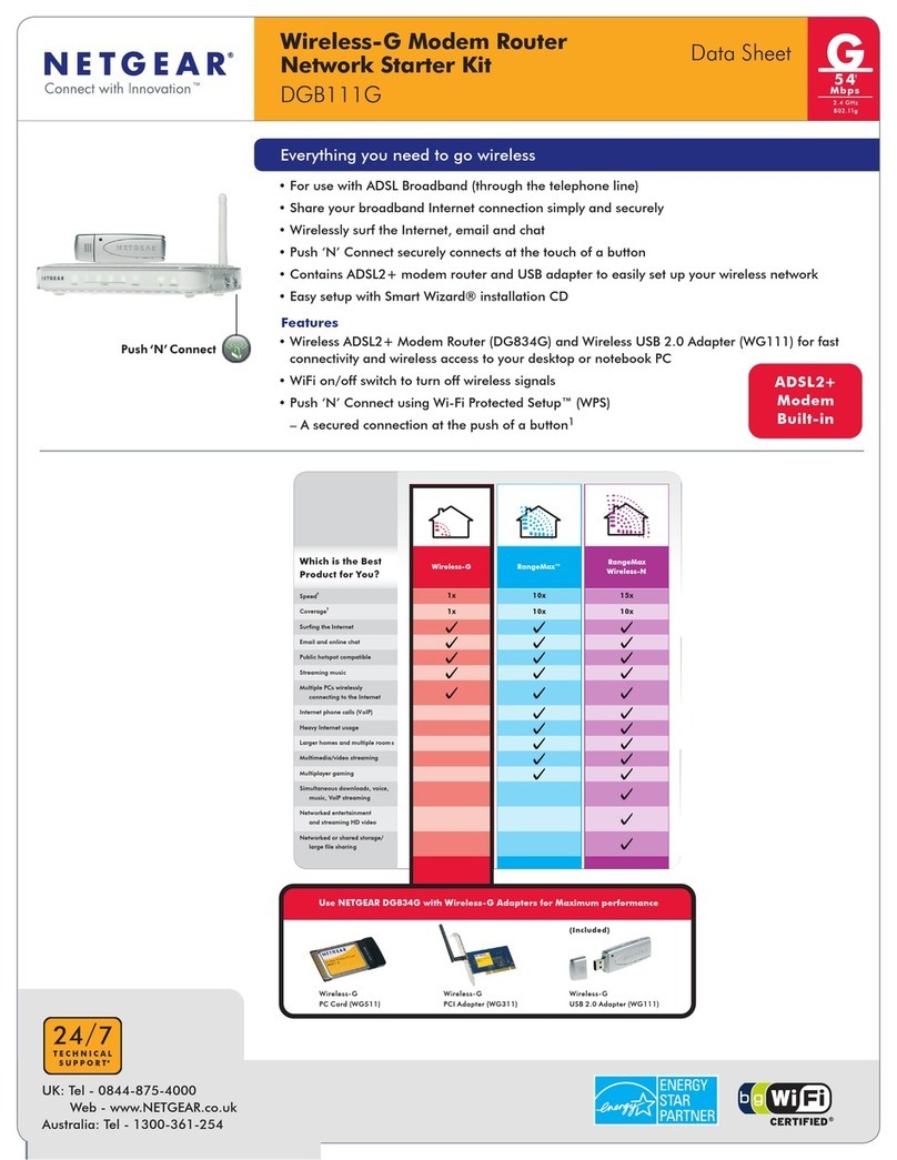
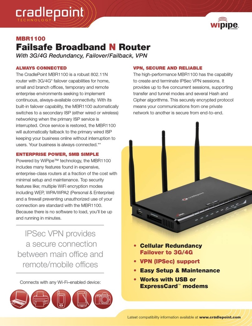
Data-Tronix DT-05PTWR300MB User manual

DT-05PTWR300MB
IEEE802.11 b/g/n 300Mbps Wireless Router
USER'S GUIDE
Version l.0

TABLE OF CONTENTS
Chapter l. Introduction
1.1 0verview
1.2 Features
1.3 Environment
1.4 Package contents
1.5 System Requirements
Chapter 2. Hardware Installation
2.1 Interface description
2.2 Hardware connection guide
Chapter3. Setup guide
3.1 TCP/IPConfiguration
3.1.1 Network Configuration for DHCP
3.2 Quick setup of PPPoE forADSLsharing
3.3 0peration Modes
3.4 Internet Settings
3.4.1 WAN settings
3.4.3 DHCPClients list
3.5 Wireless Settings
3.5.1 Basic wireless settings
3.5.2Advanced wireless settings
3.5.3 WirelessAccess Security setup
3.5.4 WPS setting(for applicable units)
3.5.5 Wireless Station list
3.6.1 MAC/IP/Port Filtering
3.6.2 Port Forwarding(Virtual Server)
3.6.4 System Security
3.6.5 Content Filtering
3.7 Administration management
3.7.1 Language, Password, NTP settings
3.7.2 Firmware Upgrade
3.7.3 Settings Management
3.7.4 Status
3.7.5 Statistics
Chapter 4.
4.1 FAQ’s
4.2 Warranty
4.3 Troubleshooting

4.4 Legal Notice
Chapter l Introduction
1.1 0verview
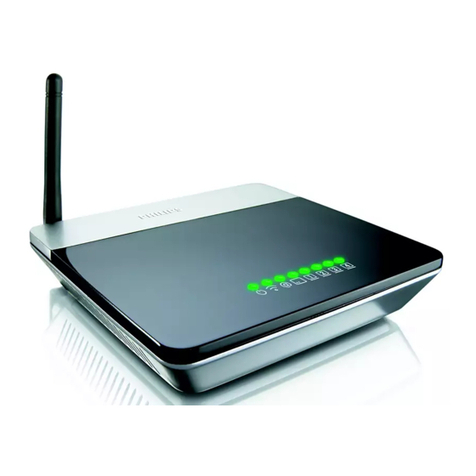
The DT-05PTWR300MB is a high performance wireless broadband router that integrates Wireless
AP, NAT-Router, 4 port Ethernet switch and a Firewall. It supports 802.11 b/g/n to supply
300Mbps of wireless bandwidth. The unit can be set to bridge or gateway mode and provide one
10/100Mbps WAN port to connect to the internet and four 10/100Mbps switch LAN ports to
expend your LAN. The DT-05PTWR300MB supports STATIC IP/DHCP
Client/PPPoE(ADSLyL2TP/PPTP) WAN connection types. It has a built in high performance
DHCP server and supports VPN Pass through. Firewall functions include MAC/IP/Port filter
and Content filter. Port forwarding ,DMZ, NTP and DDNS are supported. Wireless access
security modes are: WEP/WPA/WPA-PSK/WPA2/WPA2-PSK. Wi-Fi Protected Setup (WPS)
function. Language Supported is English for the WEB setup interface. Firmware is upgradeable
as needed.
1.2 Features:
Complies with IEEE802.11 b/g/n for wireless access
Supports a variety of wireless access security modes
Supports 64/128-bit WEP encryption security
Support WPA/WPA-PSK/WPA2/WPA2-PSK authentication and TKIP/AES
encryption security
Supports WPS easy wireless connect function
Complies with IEEE802.3 10Base-T and IEEE802.3u 100Base-TX Fast Ethernet
standards for wired LAN
One 10/100Mbps RJ45 WAN port for Internet connection
Built in four port l0/100Mbps Ethernet switch for wired LAN, SupportsAuto
MDI/MDIX
Can be set to Bridge mode and Gateway mode
WEB based setup and management interface in English
Built in high performance DHCP server with monitoring of the DHCP clients
through web setup interface
Supports MAC address and IP address binding
Supports MAC address CLONE
Supports WDS
VPN Pass through support of L2TP, IPSec, and PPTP protocols
Monitoring of wireless stations connected to this device through the web interface
High performance firewall functions include: MAC address filter, IP address filter,
Port filter, Content filter(URL and host name filter)
Supports Port forwarding and DMZ host
Changeable password by the administrator through the web setup software
System sync time with NTP server by NTP setting
Supports DDNS(Dynamic DNS) setting

Can backup and re-load current settings of the device.
Can monitor the status of the device and the statistics of the communications through web setup
software
Firmware upgrade support of root files upgrade, Uboot upgrade, and Factory Settings upgrade
1.3 Parameters and Environments
. Size: 5 7/8”(L)X4 ½”(W)X1 ¼” (H) 147(L)x113(W)x32(H)mm
. NW: 7.5 oz 206g
. Power Supply: Input AC110, Output DC9V/1A
. Consumption: 7.5W(MAX)
. Storage Temperature: -40°F to 178°F -40°C to 70 °C
. Operating Temperature: 14°F to 122°F -10°C to 50°C
. Storage Humidity: 5%-95% RH Non-condensing
. Operating Humidity: 10%-90% RH Non-condensing
1.4 Package contents
. One Wireless Broadband Router
. One PowerAdapter
. User's manual
1.5 System Requirement
. One DSL/Cable Modem
. One l0M or l0/100M ethernet card installed on your PC
. TCP/IP protocol installed on each PC
. RJ45 Twisted-pair
. Microsoft IE8.0 or later or other Internet Explorer software

Chapter 2. Hardware Installation
2.1 Interface description
2.2 Hardware connection guide
The chart is for reference only.

Chapter 3. Setup guide
3.1 TCP/IPConfiguration
1 . Click the Start button, then click Control Panel.
2. Double click the Network icon and select the Create a new connection in the Network window.
Follow the network wizard instructions until conclusion, then skip to step 6.
If you have installed TCP/IP protocol before, please skip to step 6.
3. Click theAdd button to add network adapter into your computer.
4. Double click Protocol to add TCP/IP protocol.
5. Select Microsoft item in the manufactures list, Choice TCP/IP in the Network
protocols, Click OK button to return to Network window.
6. The TCP/IP protocol should be listed in the Network window. Double click
TCP/IP to set the TCP/IP protocol.
7. Select Obtain an IP address automatically in the, IPAddress table .
8. Click OK to complete the install procedure and restart your computer to enable
the TCP/IP protocol.
3.1.1 Network Configuration for DHCP
Windows Vista
1. Select Network and Sharing in the Control Panel.
2. Click View Status click Properties.
3. Click Continue in the UserAccount Control window.
4. In the General tab of the Local Area Connection Properties window select Internet
Protocol Version 4 (TCP/IPv4), click Properties.
5. Click the Obtain an IP address automatically button.
6. Click the Obtain DNS server address automatically button.
7. Click OK in the Internet Protocol Version 4(TCP/IPv4) Properties window,
8. Click OK in the Local Area Connection Properties screen to save the settings.
Windows 7
1. Click View Network Status and Tasks in the Control Panel.
2. Click Local Area Connection, click Properties.
3. Click Internet Protocol Version 4 (TCP/IPv4), click Properties.
4. Click the Obtain an IP address automatically button.
5. Click the Obtain DNS server address automatically button.
6. Click OK in the Internet Protocol Version 4(TCP/IPv4) Properties window,
7. Click OK in the Local Area Connection Properties screen to save the settings.

Windows XP
1. Select Network Connections in the Control Panel.
2. Right-click Ethernet Local Area Connection, then click Properties.
3. In the “General” tab, select Internet Protocol (TCP/IP), click Properties.
4. The Internet Protocol (TCP/IP) Properties window appears.
5. Click the Obtain an IP address automatically button.
6. Click the Obtain DNS server address automatically radio button.
7. Click OK in the Internet Protocol (TCP/IP) Properties screen, click OK in the Local Area
Connection Properties screen to save the settings.
Windows 2000
1. Select Network Connections in the Control Panel.
2. Right-click Ethernet Local Area Connection, then click Properties.
3. In the “General” tab, select Internet Protocol (TCP/IP), click Properties.
4. Click the Obtain an IP address automatically button.
5. Click the Obtain DNS server address automatically radio button.
6. Click OK in the Internet Protocol (TCP/IP) Properties screen, click OK in the Local Area
Connection Properties screen to save the settings.
Macintosh OS X
1. Click on theApple icon in the top left corner of the desktop.
2. From the menu that appears select System Preferences.
3. The “System Preferences” window appears. Network.
4. From the Network window, make sure Ethernet (Built in Ethernet) in the list on the left is
highlighted and displays Connected.
5. From the Configure drop down menu, choose DHCP.
6. Click theApple icon to save.
3.2 Quick setup of PPPoE forADSLsharing
This will guide you to quick setup PPPoE connect with anADSL modem to share the
Internet.
1 . Connect the LAN adapter on your PC with one of LAN ports of the wireless router,
then power it on. The PC will get an IP address.
2. Open the web browser on your PC(e.g. IE), type http://192.168.8.1 in the address
field , then press Enter. Input the default User name admin and the default password admin,
then click OK button.

3. Select Gateway operation mode as in figure4
4. Click the Configuration Menu - Internet Settings - WAN, Select PPPoE (ADSU for
WAN connection type, then input your ADSL User Name and Password you received
From your ISP into the corresponding fields, as follows, then click theApply button.

5. Click Wireless Settings –Basic and Input your Network Name (SSID). Keep other
default parameters indicated in figure 6, then click Apply.
6. Setup wireless access security to prevent unauthorized access:
Options are: WPA/WPA 2/WPA-PSKIWPA2-PSK Security
Note for WPAAlgorithms: TKIP is only for 54Mbps,
Input a Password in the Pass Phrase table, then click Apply.

7. Connect the WAN port of this Router with the LAN port of the ADSL modem, then
reboot the Router andADSL modem. You can share the internet connection.
For the settings of the ADSL modem please refer to its user's guide.
3.3 0peration Mode
Please refer to fig 4 in 3.2.3, you can set this device to Bridge or Gateway
mode.
1 . Bridge mode:All ethernet and wireless interfaces are bridged into a single
bridge Interface. WAN settings do not need to be set in the Internet Settings menu.
2. Gateway mode: The first ethernet port is treated as the WAN port. The other
ethernet ports and the wireless interface are bridged together and are treated
as LAN ports. WAN settings must be set in the Internet Settings menu.
3. After you have selected a mode, wait for the device to reboot, then refresh
the setup WEB page.
Note: In Gateway mode, If you want to let PCS aquire lP addresses automatically,
you must Enable the NAT.
3.4 Internet Settings
3.4.1 WAN settings
This device provides 5 WAN connection types:
STATIC (fixed IP) DHCP (Auto config) PPPoE(ADSL) L2TP PPTP.
Select the WAN connection type required by your ISP(lnternet Service Provider),
then input the parameters into corresponding fields, click Apply.
3.4.1.1 STATIC (fixed lP)
If your ISP assigns you a fixed IP address, Select STATIC(fixed lP) as figure. 8:

IPAddress: Enter the IP address assigned by your ISP.
Subnet Mask: Enter the Subnet Mask assigned by your ISP.
Default Gateway: Enter the Gateway assigned by your ISP.
Primary DNS Server: Enter the Primary DNS IP address assigned by your ISP.
Secondary DNS Server: Enter the Secondary DNS IP address assigned by your ISP.
MAC Clone:
In some instances the ISP provides a fixed MAC address for your PC to connect to the
Internet, you can input the MAC address into the MAC Clone field to let your LAN share the
Internet connection.
The default MAC address is set to the WAN's physical interface MAC address on
the Router, So it's not recommended that you change the default MAC address.
Note: You can use the MAC Clone function option for each WAN connection type.
3.4.1.2 DHCP(Auto config) mode
If you connect to the Internet through the LAN of your ISP and do not subscribe to a fixed IP
service, you will get a different IP address each time you log on, in this case, please select
DHCP mode. The Hostname is optional but may be required by some ISPs.
If needed, you can Enable the MAC Clone function and fill in the MAC address table,
then clickApply.

3.4.1.3 PPPoE(ADSL) mode
If you connect to the Internet through a DSL line, check with your ISP if they use
PPPoE, If they do, select PPPoE. Refer to figure 5 in 3.2.4 (page 7).
Enter User Name and Password from the ISP,
You can select one Operation mode from following three:
Keep Alive: Always online;
On Demand: Connect to Internet only when you need it;
Manual: Connect to Internet manually every time.
If required, enable the MAC Clone function and input the MAC address,
then clickApply.
3.4.1 .4 L2TPmode and PPTP mode
The setting of this two mode is similar to above. Make sure of the correct
connection mode and input the User Name and Password for your IS P.
3.4.2 LAN settings
As in the following figure 11, modify the IP address of this device; Enable or Disable
DHCP Server and define the DHCP address range.

Set the IPAddress and Subnet Mask to your internal network settings.
Unless you have specific internal network needs, these should be no reason to change
the values.
DHCP Type: Can be set to Disable or Server mode. If the Server mode is
selected, configure your computers to automatic IP allocation mode. When
your computer is powered on, it will automatically load the proper TCP/IP
settings from this device.
Start IPAddress: Define an IP address for the DHCP server to start with when
issuing IP address. This address cannot be the same as the IP Address of this device.
End IP Address: Define an End IP address for the DHCP server, it must be greater
than the Start IP Address,
Primary DNS Server: Enter the Primary DNS IP address assigned by your ISP. This
is optional.
Secondary DNS Server: Enter the Secondary DNS IP address assigned by your
ISP. This is optional.
Default Gateway: Normally it's same as the IPAddress of this device.
3.4.3 DHCPClients list
The table lists the information about the hosts which have obtain an lP address
from the DHCP server of this router. As following fig. 1 2.
3.4.4 VPN Pass through
VPN Pass through can help you to achieve remote access to your LAN through an outside
Internet connection.
This device can be set to pass through VPN data packats based on the following protocols:
PPTP, L2TP, IPSec. Enable the protocols you need on the setup page as per figure 13, then click
Apply.

3.5 Wireless Settings
This device can let all wireless nodes (PC, Smart Phone, etc.) equipped with
a IEEE802.11/b/g/n wireless network adapter connect to your Intranet.
3.5.1 Basic Settings
You should configure at minimum the Wireless settings for communication, such as Network
Name (SSID) and Channel.
Network Name (SSID): The name of a wireless local area network (WLAN). All
wireless devices on a WLAN must employ the same SSID in order to communicate
with each other. The SSID is a case sensitive text string and is made up of a
sequence of alphanumeric characters (letters or numbers). SSID’s have a maximum
length of 32 characters. The default SSID of this device is Wireless Router,
but it is recommended strongly that you change your SSID to a different SSID name.
Broadcast Network Name (SSID): The router automatically transmit SSID into the
airwaves at regular intervals (every few seconds). This feature allow clients to
dynamically discover and roam between WLANs. However, this feature also makes
it easier for hackers to break into your network. Because SSIDs are not encrypted or
otherwise scrambled, It becomes easy to grab one by snooping the WLAN looking
for SSID broadcast messages coming from the router or WAP. Knowing your SSID
brings hackers one step closer to a successful intrusion, you may want to disable
this feature to improve the security of your WLAN. Once your wireless clients are
manually configured with the right SSID, they no longer require these broadcast
messages.
Frequency (Channel): This field determines which operating frequency will be
used. It is not necessary to change the wireless channel unless you notice
interference problems with another nearby access point.All devices in the same
wireless LAN should use the same channel.
3.5.2Advanced wireless settings
These settings are only for more technically advanced users who have a sufficient

knowledge about wireless LAN. These settings should not be changed unless you
know what effect the changes will have on yourAccess Point.
Beacon Interval: Beacon frames are transmitted by an access point at regular
intervals to announce the existence of the wireless network. The default behavior is
to send a beacon frame once every 100 milliseconds (or 10 per second).
Data Beacon Rate (DTIM): Indicates rate that the access point will advertise to the
network for the purposes of setting up communication with other APs and client
stations on the network. It is generally more efficient to have anAP broadcast a
subset of its supported rate sets.
Fragment Threshold: Setting the Fragment Threshold can limit the size of packets
(frames) transmitted over the network. If a packet exceeds the fragmentation
threshold set here, the fragmentation function will be activated and the packet will
be sent as multiple 802.11 frames. The default is 2346.
RTS Threshold: The RTS threshold specifies the packet size of a request to send
(RTS) transmission. This helps control traffic flow through the access point,
especially one with a lot of clients. The default is 2347
TX Power: Set from l - 100 to control the RF output power. This controls the distance of the
RF signal transmitted.
3.5.3 WirelessAccess Security setup
Setup the wireless security and encryption to prevent unauthorized access and
monitoring. It is recommended strongly that you choose this option to encrypt your
wireless network. The Security mode supports WEP(Open/Shared/Auto),
WPA/WPA- PSK/WPA 2/WPA 2-PSK. You must setup the same security
parameters both on your router and the wireless client devices.
3.5.3.1 WEP(Open/Shared/Auto)
WEP is a protocol that adds security to WLAN based on the 802.11b standard . WEP
was designed to give wireless networks the equivalent level of privacy protection as
a comparable wired network.As per figure 16 below, You can pre-set 4 WEP keys. The format
can beASCII or Hex string, Only the key you selected in the Default Key setting will be used.

3.5.3.2 WPA/WPA-PSK/WPA2/WPA2-PSK
WPA provides significantly stronger wireless data encryption than WEP.
Refer to fig. 7 in 3.2.6(page 8). You can choice a Security Mode from:
WPA/WPA-PSK/WPA 2/WPA 2-PSK then choice a WPAAlgorithm from:
TKIP orAES. TKIP is only for 802.11 b/g (54Mbps max). For faster connection
speeds greater than 54Mbps, select AES or TKIP WPA algorithms.
If WPA or WPA2 is to be selected, you must Enter the settings of the
Radius Server (lP address, Port, etc.).
If WPA-PSK or WPA2-PSK is to be selected, you must input a Pass Phrase.
Radius Server: In WPA authentication mode, the keys can be managed using two
different mechanisms: WPA can either use an external authentication server (e.g.
RADIUS) and EAP like IEEE802.1x, or pre-shared keys without the need
for additional servers(as above WPA-PSK,WPA2-PSK.. .).
3.5.4 WPS setting
WPS (WiFi Protected Setup) can help you quickly and easily setup the connection
between the router and clients. Using the WPS function, you do not need to select the
Security mode and set the Encryption Key. You just need to input the correct PIN code or
select the PBC (or press the WPS button on the front panel) to setup WPS.
Select Wireless Settings: Select WPS in the main menu to enter the WPS setting page as
In figure 17:

WPS: Enable or Disable the WPS function. The default is Disable.
WPS mode: You can set the WPS mode in WPS Progress section, There are two modes
for your selection: PIN code or PBC (Push-Button Configuration).
PIN mode: If you select the PIN mode WPS, you must know the PIN code of the client
node and input the PIN into the PIN field. You also can press the Generate button in the WPS
Summary field to generate a PIN code as the common PIN code for the router and clients.
The router and clients must use the same PIN code.
PBC mode: Select PBC then pressApply, or push the WPS button on the front
panel for about l second. Use the WPS/PBC mode in client nodes to connect with the router.
WPS button operation: After you push the WPS button for 1 second, the WPS indicator will blink
for about 2 minutes. This means the WPS is sending out signals during this period of time.
The client device can authenticate by WPS/PBC function during this time.
After a successful connection, the WPS indicator will shut off. You can repeat this step
For up to 32 client connections.
WPS Status:
Idle - WPS service is in standby.
Start MAC process - WPS access has started and is waiting for clients connect.
Configured - Client has authenticated successfully and connected.
Reset OOB:After you press this button, the WPS server will go to the Idle status.
The WPS indicator will shut off. The AP will not respond to any WPS request from the clients
The system will set the Security mode into WPA.
3.5.5 Wireless Station list
Select Wireless Settings, then select Station List in the main menu, and view the Station list table
as indicated in figure 18. Here you can monitor the client stations which are associated with the
Router through this table.

3.6 Firewall
The system provided firewall functions include: MAC/IP/Port filtering,
Content Filtering, Port Forwarding, System Security and DMZ, to help prevent your
network from a hacker attack or to limit some clients' access.
3.6.1 MAC/IP/Port Filtering
Select Firewall, then MAC/IP/Port Filtering from the main menu to enter the page
as indicated in figure 19. Input the MAC address or IP address and Port range into
the corresponding fields. Select a Protocol you want to filter, and select the action
of Drop orAccept, then click Apply. The setting will append to the Current MAC
IP Port filtering rules in system table. Repeating this step, you can set all the
filter rules you want into this table. After your finished, access from the Internet
or LAN that matches the rules in the table will be Dropped or Accepted depending
on the correspondingAction setting thus limiting the clients' access.
3.6.2 Port Forwarding (Virtual Server)
If you configure the router for Virtual Server use, remote users accessing services such
as the Web or FTP at your local site via a public IP address can be automatically
redirected to local servers configured within your private IP addresses. In other words,
depending on the requested server (TCP/UDP port number), the router redirects the
external service request to the appropriate server.
Before using Virtual Server, You should add a static IP address to the designated
PC. You can add a Virtual Server by using the interface in figure 20:

1. Select Virtual Server Settings to Enable;
2. Enter the IP address of the Virtual Server into the IPAddress field;
3. Enter the Port range you want to forward into the Port Range field;
4. Select a Protocol of TCP, UDP, or TCP&UDP;
5. Enter the Service name into the Comment field;
Once done, click Apply to add into the Current Virtual Servers in the system table.
Repeat the above steps to add up to 32 Virtual Server settings.
You can select any current entry under Current Virtual Servers in the system table,
then click the Delete Selected button to delete it.
3.6.3 DMZ
If you have a client PC that cannot run an Internet application properly from behind
the NAT firewall or after configuring the Virtual Server, then you can open the client up
to unrestricted two-way Internet access.
Set the DMZ Settings to Enable, Enter the IP address of a DMZ host in the DMZ IP
Address field, then click theApply button.
Adding a client to the DMZ (Demilitarized Zone) may expose your local network to a
variety of security risks. Evaluate this option carefully prior to using.
3.6.4 System Security
You may configure the system firewall to help prevent the AP/Router from an attack.
Click Firewall, then System Security from main menu. Enter the page as per figure 22.

1. You can Deny orAllow Remote management from the WLAN.
2. You can Enable or Disable Ping form the WAN.
3. You can Enable or Disable Stateful Packet Inspection (SPI).
3.6.5 Content Filtering
You can set the Web content filter, Web URL filter, and Web HOST filter with this
function. Click Firewall, then content Filtering to enter the pages containing figures
23-25:
1. Webs Content Filter: you can choose Proxy, Java or ActiveX to filter, then click
Apply. The corresponding contents from the web will be filtered and will not display
on Internet Explorer or other Internet Browsers.
2. Webs URL Filter: If you want to block the client access to a certain web page,
input the URLaddress of the page into the URL field in the Add a URL filter table, then
click Apply.
Table of contents
