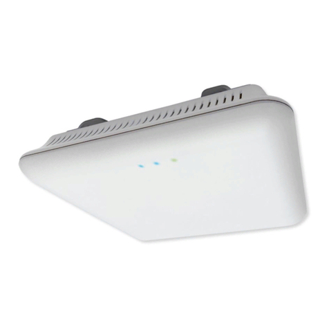
Datasat DN200 User manual

DN200
Outdoor Wireless Intelligent
Access Point
Installation and User Guide
Version 1.42 Rev .7
Effective Date: Jan 2012
Document # 4001
Datasat Technologies
5 Tavistock Estate
Ruscombe Lane, Twyford RG10 9NJ
UK
Datasat Technologies
96 1 Topanga Canyon Place
Chatsworth, CA 91 11
USA

DN200 User Manual Rel 1.0
Notices
This product contains software proprietary to Datasat Technologies and protected by US and International
copyright law. Unauthorized reproduction or disclosure, in whole or in part, is strictly prohibited.
The software and methods implemented in this product may be protected by US Patent “METHOD AND
SYSTEM FOR PROVIDING INFORMATION ACCESS, MULTIMEDIA CONTENT ACCESS, AND
PHONE CONNECTIVITY” Docket num er 57956-100 and other US and International patents, both issued and
pending.
WARRANTY/LIMITATION OF LIABILITY
E CEPT FOR THE LIMITED WARRANTY PROVIDED HEREIN, THIS PRODUCT IS PROVIDED "AS IS"
AND WITHOUT WARRANTY OF ANY KIND. DATASAT TECHNOLOGIES E PRESSLY DISCLAIMS
ALL OTHER WARRANTIES, E PRESS AND IMPLIED, INCLUDING, BUT NOT LIMITED TO, THE
IMPLIED WARRANTIES OF MERCHANTABILITY AND FITNESS FOR A PARTICULAR PURPOSE.
DATASAT TECHNOLOGIES DOES NOT WARRANT THAT THIS PRODUCT WILL MEET USER’S
REQUIREMENTS, OR THAT THE OPERATION OF THIS PRODUCT WILL BE UNINTERRUPTED OR
ERROR-FREE, OR THAT DEFECTS IN THIS PRODUCT WILL BE CORRECTED. UNDER NO
CIRCUMSTANCES, INCLUDING NEGLIGENCE, SHALL DATASAT TECHNOLOGIES, OR ITS
DIRECTORS, OFFICERS, EMPLOYEES OR AGENTS, BE LIABLE TO USER FOR ANY INCIDENTAL,
INDIRECT, SPECIAL OR CONSEQUENTIAL DAMAGES (INCLUDING DAMAGES FOR LOSS OF
BUSINESS PROFITS, BUSINESS INTERRUPTION, LOSS OF BUSINESS INFORMATION, AND THE LIKE)
ARISING OUT OF THE USE, MISUSE OR INABILITY TO USE THIS PRODUCT OR RELATED
DOCUMENTATION.
INFORMATION TO THE USER
The user’s manual or instruction manual for an intentional or unintentional
radiator shall caution the user that changes or modifications not expressly
approved by the party responsible for compliance could void the user’s authority
to operate the equipment. In cases where the manual is provided only in a form
other than paper, such as on a computer disk or over the Internet, the
information required by this section may be included in the manual in that
alternative form, provided the user can reasonably be expected to have the
capability to access information in that form.
This Device complies with Part 15 of the FCC Rules. Operation is subject to the
following two con itions:
(1) this evice may not cause harmful interference, an
(2) this evice must accept any interference receive , inclu ing interference that
may cause un esire operation
Copyright
DN200
Outdoor Wireless Access Point,
Installation and User Guide
© 2012 Datasat Technologies. All right reserved.
The content of this publication is subject to change without notice. Datasat Technologies assumes no obligation to
notify you of any changes or updates. While Datasat Technologies believes this publication is accurate, due to
ongoing improvements and revisions, Datasat Technologies cannot guarantee the accuracy of printed material, nor
can it accept responsibility for errors or omissions. Datasat Technologies may periodically publish updates and
revisions to this publication as it deems necessary.

DN200 User Manual Rel 1.0
All other trademarks are the properties of their respective owners.
Document No. 4001_DN200_Manual_Rev3.7
January 2012
Record of Changes
Manual Version /
Date
Description
June, 2011 Preliminary version
Au ust, 2012 Chan es as per FCC requirements

DN200 User Manual Rel 1.0
TABLE OF CONTENTS
1.0 PRE-INSTALLATION PLANNING 11
1.1 BACKHAUL LINK PLANNING 11
1.1.1 US FCC BANDS AND RULES 11
1.1.2 SAMPLE CALCULATIONS ON EIRP 13
1.1.3 SAMPLE POINT-TO-POINT LINK BUDGET 13
1.1.4 DATA RATES 16
1.1.5 RADIO PATH PLANNING 16
1.2 ANTENNA HEIGHT 17
1.2.1 ANTENNA POSITION AND POLARIZATION 17
1.2.2 RADIO INTERFERENCE 1
1.2.3 WEATHER CONDITIONS 1
1.3 ETHERNET CABLING 1
1.4 GROUNDING 1
1.5 SYSTEM SETUP 19
1.5.1 ACCESSING THE WEB INTERFACE (GUI) 19
1.5.2 LAN PORT (POWER OVER ETHERNET) 22
1.6 SYSTEM CONFIGURATION 22
1.7 NAT/FIREWALL 23
1. MULTICAST CONTROL 24
1.9 ADMINISTRATION 25
1.9.1 ADDING USERS & CHANGING PASSWORD 25
1.10 DHCP CONFIGURATION 25
1.11 SITE SURVEY 2
1.12 BEFORE INSTALLING 29
1.12.1 TESTING BASIC LINK OPERATION 29
1.13 MOUNT THE DN200 UNIT - POLE-MOUNTING 30
1.14 CONNECT EXTERNAL ANTENNAS 32
1.14.1 FREQUENCY, WAVELENGTH AND VELOCITY 33
1.14.2 THE DECIBEL 33
1.15 CONNECT A GROUNDING WIRE TO THE DN200 34

DN200 User Manual Rel 1.0
1.16 CONNECT ETHERNET CABLE TO THE DN200 34
1.17 CONNECT THE EXTERNAL DC POWER 35
1.17.1 DN200 STANDARD CONFIGURATION 35
1.17.2 DN200 CONFIGURED WITH THE INTERNAL POE ENABLED. 35
1.17.3 WIRING AN EXTERNAL SUPPLY. 36
1.1 CONNECTING THE OPTIONAL EXTERNAL POWER INJECTOR (9004H49000)
36
1.19 ANTENNA ALIGNMENT 37
1.19.1 VIBRATION CERTIFICATION 39
2.0 SPECIFICATIONS 40
2.1 PRODUCT FEATURES 40
2.2 ETHERNET COMPATIBILITY 40
2.3 POWER OVER ETHERNET 40
2.4 RADIO CHARACTERISTICS 40
APPENDIX A: Approved antenna configuration

DN200 User Manual Rel 1.0
Introduction
The Datasat DN200 is a rugged, full outdoor quad-radio 2x2 MIMO outdoor-rated wireless network
system that is designed for the deployment of advanced IEEE 802.11 wireless services in harsh
environments. The DN200 can provide IEEE 802.11 wireless service to local wireless clients by
simultaneously providing backhaul and access services from the same unit with no bandwidth reduction.
Not only can the DN200 simultaneously provide 802.11 a/b/g/n services from the same unit by using
multiple interfaces, it can also inject inline power to PoE capable devices, such as cameras, attached
directly, thus eliminating home run cabling. Aside from being able to power directly attached external
devices, the DN200 itself is capable of being powered through PoE with an optional PoE injector.
Two or more DN200 models can provide point-to-point or point-to-multipoint links between remote
Ethernet LANs, and can simultaneously serve wireless service for local clients. The wireless system
offers a fast, reliable, and cost-effective solution for connectivity between remote Ethernet LANs or to
provide Internet access to an isolated site. The DN200 is unique as it is a multi radio, multi band and
multi mode system, that can be used in a multiple scenarios by skilled network planners.
The DN200 is a stand-alone device that provides the following capabilities:
• Dual Band Wireless Access Point (802.11a/b/g/n) with support for wireless access over 5 GHz or
2.4Ghz
• Point-to-point and point-to-multipoint access point, bridge and router functions for 5 GHz and 2.4
GHz
• Eight RP-TNC type detachable antenna interfaces, two of each for every radio. Please note: Only
approved and link budget safe antennas may be used with the DN200. Using non-approved antennas
may violate local regulations and it is the duty of the installer to check the legality of the link budgets
conducted.
• Two Gigabit Ethernet interfaces, with Power over Ethernet IN/OUT. The PoE implementation partly
complies with the 802.3at standard. For pin-outs and correct cabling, please get in touch with Datasat
Technologies for PoE implementation.
The DN200 requires detachable antennas, sold separately. Please see Appendix A for details on antennas.
Datasat Technologies’ DN200 Wireless network systems are radio transmission devices and as such are
subject to governmental regulations. Datasat Technologies Wireless network systems are sold through
authorized, non-retail, distribution channels and are required to be deployed by a Professional Installer /
Qualified Network Administrator. The professional installer responsible for the configuration and
operation of Access Points must ensure that the installation complies with local regulations, frequencies,
channels and output power.

DN200 User Manual Rel 1.0
Limited Warranty
Datasat Technologies software is warranted against defects for a period of 90 days from the date of the
original purchase. DN200 hardware is warranted against defects in material and workmanship for a
period of one year from the date of the original purchase. This warranty includes parts and labor.
THIS WARRANTY E CLUDES UNITS THAT HAVE BEEN MODIFIED, REPAIRED BY
UNAUTHORIZED PERSONNEL, OR DAMAGED BY ABUSE, IMPROPER OPERATION, DIRT,
MOISTURE OR STATIC ELECTRICITY. PROPER OPERATION OF THIS EQUIPMENT
REQUIRES THE USE OF A SURGE PROTECTOR. SUPPLYING POWER TO THE DN200 UNIT
WITHOUT THE USE OF A PROPERLY FUNCTIONING SURGE PROTECTOR WILL VOID THIS
WARRANTY.
Products being returned under warranty should be sent to Datasat Technologies freight prepaid in the
original or equivalent packaging. Please contact Datasat Technologies prior to shipping any parts or
merchandise to receive a Return Merchandise Authorization number. Datasat Technologies’s shipping
address is:
Datasat Technologies
Attn: RMA #
9631 Topanga Canyon Place
Chatsworth, CA 91311
U.S.A.
Product Improvements and pgrades
Datasat Technologies reserves the right to make changes and/or improvements to its products, without
notification and without incurring any obligation to incorporate such changes or improvements in
products previously sold or shipped.
To receive notification about upgrades or bulletins that may become available from time to time, please
complete the enclosed Warranty Card and mail or fax it to Datasat Technologies.
Visit our website at www.datasattechnologies.com.
FACTORY WARRANTY INFORMATION
Please fill in the enclosed WARRANTY information card.
Datasat Technologies requires the above information to provide proper and timely technical support.
Please fill out this page and send to:
Datasat Technologies Customer Service
9631 Topanga Canyon Place
Chatsworth, CA 91311
U.S.A.

DN200 User Manual Rel 1.0
Support Contact Information
To contact Datasat Technologies’ Technical Support staff:
Customer Service:
H
getconnected@datasat.com
H
Technical Support:
H
getsupport@ datasat.com
H
Technical Support Europe:
H
getsupport@ datasat.com
Software License Agreement
IMPORTANT: READ THIS SOFTWARE LICENSE ("LICENSE") CAREFULLY BEFORE
USING THE DATASAT TECHNOLOGIES SOFTWARE. THE SOFTWARE RESIDING ON
THE DN200 AND ANY ACCOMPANYING MATERIALS (COLLECTIVELY, THE
“SOFTWARE”) ARE LICENSED, NOT SOLD. BY USING THE DN200 , YOU ARE
ACCEPTING AND AGREEING TO THE TERMS OF THIS LICENSE. IF YOU DO NOT
AGREE TO THE TERMS OF THIS LICENSE, DO NOT USE THE DN200 .
1. Grant. Subject to your compliance with the terms of this License, Datasat Technologies
hereby grants you a non-exclusive, non-transferable, revocable, limited license to use the
Software solely for your internal business purposes and solely in connection with the
DN200 . All rights not expressly granted to you are reserved by Datasat Technologies.
2. Ownership. All right, title and interest in and to the Software, all physical copies thereof
and all intellectual property embodied therein are and shall remain vested in Datasat
Technologies. You do not own the Software, physical copies thereof or any intellectual
property embodied therein.
3. Restrictions. You may not (i) copy, distribute, sublicense, lease, transfer or use for
external purposes the Software; (ii) reverse engineer, decompile, disassemble, translate,
modify, attempt to reveal the source code of the Software, or (iii) create derivative works
from the Software.
4. Termination. Datasat Technologies may terminate this license at any time if you violate
the terms of this license. Upon termination, you must destroy the Software and related
documentation.
5. LIMITATION ON WARRANTY. YOU EXPRESSLY ACKNOWLEDGE AND AGREE THAT USE
OF DATASAT TECHNOLOGIES SOFTWARE AND HARDWARE IS AT YOUR SOLE RISK.
DATASAT TECHNOLOGIES DOES NOT WARRANT THAT THE OPERATION OF THE
SOFTWARE OR THE HARDWARE WILL BE UNINTERRUPTED OR ERROR FREE. TO THE
MAXIMUM EXTENT PERMITTED BY APPLICABLE LAW, THE DATASAT TECHNOLOGIES
SOFTWARE AND HARDWARE PROVIDED “AS IS,” WITH ALL FAULTS AND WITHOUT
WARRANTY OF ANY KIND, INCLUDING, WITHOUT LIMITATION, THE IMPLIED
WARRANTIES OF MERCHANTABILITY, FITNESS FOR A PARTICULAR PURPOSES, AND NON-
INFRINGEMENT OF THIRD PARTY RIGHTS, ALL OF WHICH ARE HEREBY EXPRESSLY
DISCLAIMED.
6. LIMITATION OF LIABILITY. UNDER NO CIRCUMSTANCES, INCLUDING, WITHOUT
LIMITATION, NEGLIGENCE, SHALL DATASAT TECHNOLOGIES OR ITS DIRECTORS,
OFFICERS, EMPLOYEES OR AGENTS BE LIABLE FOR PERSONAL INJURY, OR ANY
INCIDENTAL, SPECIAL, INDIRECT OR CONSEQUENTIAL DAMAGES WHATSOEVER,
INCLUDING, WITHOUT LIMITATION, DAMAGES FOR LOSS OF PROFITS, LOSS OF DATA,
BUSINESS INTERRUPTION OR ANY OTHER COMMERCIAL DAMAGES OR LOSSES, ARISING

DN200 User Manual Rel 1.0
OUT OF OR RELATED TO YOUR USE OF THE DATASAT TECHNOLOGIES SOFTWARE OR
HARDWARE, HOWEVER CAUSED, REGARDLESS OF THE THEORY OF LIABILITY AND EVEN
IF DATASAT TECHNOLOGIES HAS BEEN ADVISED OF THE POSSIBILITY OF SUCH
DAMAGES. IN NO EVENT SHALL DATASAT TECHNOLOGIES’S LIABILITY EXCEED THE
AMOUNT PAID TO DATASAT TECHNOLOGIES. SOME STATES DO NOT ALLOW THE
LIMITATION AND/OR EXCLUSION OF LIABILITY FOR INCIDENTAL OR CONSEQUENTIAL
DAMAGES, SO THE ABOVE LIMITATION OR EXCLUSION MAY NOT APPLY TO YOU.
7. General. This License shall be governed by the laws of the State of California as applied to
contracts performed wholly therein. In any action brought by either party arising out of
this License, the prevailing party shall be entitled to recover its reasonable attorney’s fees
and costs. If any provision of this License is held by a court of competent jurisdiction to be
unenforceable or if a provision of this License is waived by either party, the remainder of
this License shall remain in full force and effect. You may not assign this License without
the prior, express written consent of Datasat Technologies.

DN200 User Manual Rel 1.0
npacking
The packaging is designed to handle normal shipping and handling. Upon receipt of shipment, check for
signs of damage before opening and report all damage to the carrier. All shipments made from Datasat
Technologies are customer responsibility once they leave our premises.
Before installation begins, we suggest that a complete inventory be taken to minimize problems or
questions during installation. Additionally, save all packing material until installation is complete in the
unlikely event that a component(s) requires return to the factory. Use the packing slip that came with
your unit to verify received inventory.
The following is a standard packing list for the DN200:
Table 1. DN200 Standard Packing Kit
ITEM DESCRIPTION QTY
Win nut, M6 18-8 stainless steel (for pole mountin ) 4
Washer, flat, M6, 12mm OD, 18-8 stainless steel (for pole mountin ) 6
Washer, split rin lock (for pole mountin ) 6
Screw, hex socket cap, M6-16mm, 18-8 stainless steel (for pole mountin ) 2
Bolt, flat head carria e, M6-93mm (for pole mountin ) 4
Clamp, Pole mountin (for 1.0"-2.5" poles) 4
Hex key, M6 1
DC connector, weatherproof 1
Weatherproof RJ45 boot 2
Outdoor Power supply (If ordered) 1
The following is a list of optional parts for the DN200 (sold separately)
Table 2. DN200 Optional parts
ITEM DESCRIPTION
POE injector kit
Outdoor Power Supply

DN200 User Manual Rel 1.0
1.0 Pre-Installation Planning
1.1 Backhaul Link Planning
The DN200 supports fixed point-to-point or point-to-multipoint wireless links. A single point to point
link can be used to connect a remote site to a larger core network. Multiple point to point links can
provide a way to connect widespread Ethernet LANs, and provide a high capacity backhaul. For each
link in a wireless routed network to be reliable and provide optimum performance, some careful site
planning is required. This chapter provides guidance and information for planning wireless links.
1.1.1 US FCC Bands and Rules
The rules and regulations listed below can change without notice. It is the duty of the installer/customer to check
local regulations
•
5.15-5.25 GHz. Regulations require use of an integrated antenna. Power limited to 50mW
(17dBm)
•
5.25-5.35 GHz. Regulations allow for a user-installable antenna, subject to Dynamic Frequency
Selection (DFS, or radar avoidance). Power limited to 250mW (24dBm). The DN200 Radio
does not support DFS/Radar avoidance in this and. This and is not availa le for
equipment supplied to FCC regulatory regions. For DFS support kindly email us and more
information can e provided.
•
5.47-5.725 GHz. Both outdoor and indoor use, subject to Dynamic Frequency Selection (DFS,
or radar avoidance). Power limited to 250mW (24dBm). A professional, as described in FCC
Part 15.247 and 15.407 must install devices operating in this frequency range. This means that
the professional installer must understand the legal limitations of antenna gain and transmitter
output power (EIRP), as well as the type of installation whether it is for point-to-point (fixed) or
point-to-multipoint. (see table 1.1.2). The DN200 Radio does not support DFS/Radar
avoidance in this and. This and is not availa le for equipment supplied to FCC
regulatory regions. For DFS support kindly email us and more information can e
provided.
•
5.725 to 5.825 GHz. Regulations allow for a user-installable antenna. Power limited to 1W.
•
Part 15.247(c)(iii) states the following:
(c) Operation with directional antenna gains greater than 6 dBi.
(1) Fixed point-to-point operation:
(i) Systems operating in the 2 00-2 83.5 MHz band that are used exclusively for fixed, point-to-
point operations may employ transmitting antennas with directional gain greater than 6 dBi
provided the maximum conducted output power of the intentional radiator is reduced by 1 dB for
every 3 dB that the directional gain of the antenna exceeds 6 dBi.
(ii) Systems operating in the 5725-5850 MHz band that are used exclusively for fixed, point-to-
point operations may employ transmitting antennas with directional gain greater than 6 dBi
without any corresponding reduction in transmitter conducted output power.
(iii)Fixed, point-to-point operation, as used in paragraphs (c)(1)(i) and (c)(1)(ii) of this section,
excludes the use of point-to-multipoint systems, omnidirectional applications, and multiple co-
located intentional radiators transmitting the same information. The operator of the spread
spectrum or digitally modulated intentional radiator or, if the equipment is professionally
installed, the installer is responsible for ensuring that the system is used exclusively for fixed,
point-to-point operations.
•
As per Part 15. 07(a)(1) , for the band 5.15-5.25 GHz, if transmitting antennas of directional
gain greater than 6 dBi are used, both the maximum conducted output power and the peak
power spectral density shall be reduced by the amount in dB that the directional gain of the
antenna exceeds 6 dBi

DN200 User Manual Rel 1.0
•
To Comply with safe operating distance rules, in the 5.745GHz-5.825GHz band, antennas
should be installed at least 4.47m away from all persons.
FCC 2.4GHz Band Rules (Point-to-Multipoint)
Maximum Power from Intentional Radiator Maximum Antenna Gain (dBi) EIRP (dBm)
30dBm or 1 Watt 6 36
27dBm or 500mW 9 36
24dBm or 250mW 12 36
21dBm or 125mW 15 36
FCC 2.4GHz Band Rules (Point-to-Point)
Maximum Power from Intentional Radiator Maximum Antenna Gain (dBi) EIRP (dBm)
30dBm or 1 Watt 6 36
27dBm or 500mW 15 42
24dBm or 250mW 24 48
22dBm or 160mW 30 52
NOTE:
• The FCC Terminology of Intentional Radiator is the transmitter power of the wireless equipment
such as Access point, router or bridge
• THE FCC rules state that for 2.4GHz Point to Point operation, for every 1 dBm the intentional
radiator is reduced below the initial 30dBm, the antenna gain may be increased from the initial
6dBi by 3dBi
• EIRP or Equivalent Istropically Radiated Power (EIRP) is terminology for the total RF power
radiated by the antenna.

DN200 User Manual Rel 1.0
1.1.2 Sample Calculations on EIRP
Frequency
(GHz)
Permitted se P-to-P
Transmitter
Max Power
Output
P-
TO
-P
EIRP Max
(gain+power)
P-to-MP
Transmitter
Max Power
Output
P-
TO
-MP
EIRP Max
5.15-5.25 Indoor-
Integrated
antenna
50mW
(17dBm)
200mW
(23dBm)
50mW
(17dBm)
200mW
(23dBm)
5.725-5825 Outdoor 1W
(30dBm)
200W
(53dBm)
1W
(30dBm)
4W
(36dBm)
If EIRP exceeds the legal limit as demonstrated in this table, transmitter output power must e
decreased to bring EIRP within legal constraints. For example, if you deploy a point to multi-point
antenna on frequency 5.745GHz with a 10dBi gain, you must decrease the transmitter output power to
4dBm. Note: Some channels only operate at 20MHz channel width (HT20), while others can operate at
40MHz channel width (HT40). The HT40 channels will provide a higher throughput.
NOTE: IT IS HIGHLY ADVISED THAT A PROFESSIONAL FREQUENCY MANAGEMENT PLAN
IS IMPLEMENTED, TO ENSURE MA IMUM SPECTRAL EFFICIENCY. DATASAT
TECHNOLOGIES CAN PROVIDE SUCH A PLAN IF REQUIRED.
1.1. Sample Point-To-Point Link Budget
A 5GHz sample link budget is shown. A 2.4GHz budget should also be conducted keeping in mind 1.1.1
Parameter INP T VAL ES nits Source, notes
Transmitter
Power
16
dBm manufacturer data, may vary with the number of Tx
antenna u ed. (The DN200 can be u ed at 20dBm,
ba ed on local regulatory law )
Transmit cable
loss
-2.5
dB from cable data. Typically in dB/100ft. Lo = length (ft)
x lo /100 Shown a a -ve dB gain.
Transmit antenna
gain
10
dBi antenna data. In a MIMO array the gain of the main
(centre) antenna in the direction of the co-polar
receive antenna hould be u ed. The dBi unit = gain rel
to i otropic antenna. Antenna gain may al o be quoted
in dBd (gain rel to dipole) in which ca e add 2.2 dB to
get the gain in dBi
Transmitter EIRP 23.5
dBm CALC LATED EIRP = Tx power +cable lo (-dB) +
antenna gain

DN200 User Manual Rel 1.0
Path Loss -110
dB propagation lo between tran mit antenna and receive
antenna highly variable - hown a a -ve gain. Depend
on the frequency and number and type of ob truction
within the Fre nel zone within the Fre nel zone of the
propagating wave. See path lo graph .
Receive Antenna
Gain
10
dBi antenna data - ee above
Receiver cable
loss
-2.5
dB hown a a -ve dB gain. See tran mitter cable lo .
Receiver
threshold
-80
dBm the minimum ignal level required for a pecific
throughput and bit-error rate. The thre hold at the
higher throughput level achievable in 802.11n y tem
i ignificantly higher than required for 11 Mb/ ec.
Noi e i al o a con ideration when figuring the receiver
thre hold. (i.e. Noi e floor i 75dBm, that will be your
receiver thre hold ince it’ the higher number)
CALC LATED
VAL ES
Receive Signal
Level
-79
dBm the ignal power delivered to the receiver input
Path Margin 1
dB thi i the difference between the Rx ignal and the Rx
thre hold.
a rea onable margin (10 dB) i e ential on a wirele
link to allow for variation of path lo . The margin may
be reduced if diver ity antenna are u ed or MIMO
operation i po ible

DN200 User Manual Rel 1.0
Where,
r^2 = LOS (Line of Sight): no obstructions between the antennas or near the direct path. path loss
exponent = 2
r^3 = NLOS (Non line of sight) direct path is partially obstructed, creating weak multipath. Path loss
exponent =3
r^4 = NLOS (Non line of sight) path is completely obstructed, creating strong multipath. Path loss
exponent =4

DN200 User Manual Rel 1.0
1.1.4 Data rates
Under ideal deployment conditions (line of sight, low interference, and low atmospheric moisture), the
DN200 can provide a high-speed connection using a high gain 5 GHz antenna. The range depends on the
type of antenna, the frequency and mode of operation used. The maximum data rate for a link decreases
as the operating range increases. Channel width (HT20, HT40), modulation used and atmospheric
conditions affect throughput and range.
When planning a wireless link, take into account the maximum distance and data rates for the various
antenna options.
.
1.1.5 Radio Path Planning
The wireless link requires a “radio line of sight” between the two antennas for optimum performance.
The concept of radio line of sight involves the area along a link through which the bulk of the radio
signal power travels. This area is known as the first Fresnel Zone of the radio link. For a radio link, no
object (including the ground) must intrude within 60% of the first Fresnel Zone.
The following figure illustrates the concept of a good radio line of sight.
If there are obstacles in the radio path, there may still be a radio link but the quality and strength of the
signal will be affected. Calculating the maximum clearance from objects on a path is important as it
directly affects the decision on antenna placement and height. It is especially critical for long-distance
links, where the radio signal could easily be lost.
N
OTE
: For wireless links less than 500 m, the IEEE 802.11a radio signal will tolerate some obstacles in
the path and may not even require a visual line of sight between the antennas.
When planning the radio path for a wireless link, consider these factors:

DN200 User Manual Rel 1.0
• Avoid any partial line of sight between the antennas
• Be cautious of trees or other foliage that may be near the path, or may grow and obstruct the
path
• Be sure there is enough clearance from buildings and that no building construction may
eventually block the path
• Check the topology of the land between the antennas using topographical maps, aerial
photos, or even satellite image data (software packages are available that may include this
information for your area)
1.2 Antenna Height
A reliable wireless link is usually best achieved by mounting the antennas at each end, high enough for a
clear radio line of sight between them. The minimum height required depends on the distance of the link,
obstacles that may be in the path, topology of the terrain, and the curvature of the earth (for links over 3
miles). For long-distance links, the AP may have to be mounted on masts or poles that are tall enough to
attain the minimum required clearance. Use the following table to estimate the required minimum
clearance above the ground or path obstruction (for 5 GHz links).
1.2.1 Antenna Position and Polarization
Once the required antenna height has been determined, other factors affecting the precise position of the
wireless Access Point must be considered:
• Be sure there are no other radio antennas within 2 m (6 ft) of the wireless access point. These include
other Wi-Fi radio antennas
• Place the wireless access point away from power and telephone lines
• Avoid placing the wireless device too close to any metallic reflective surfaces, such as roof-installed
air-conditioning equipment, tinted windows, wire fences, or water pipes. Ensure that there is at least 5
feet clearance from such objects
• The wireless device antennas at both ends of the link must be positioned with the same polarization
direction, either horizontal, vertical or diagonal slant. Proper alignment helps to maximize
throughput. Ensure, the antennas are aligned to the main lobes and not mis-aligned to side lobes. The
link will give reduced SNR (Signal to Noise Ratio) and be unstable.

DN200 User Manual Rel 1.0
The wireless device’s antenna sends a radio signal that is polarized in a particular direction. The
antenna’s receive sensitivity is also higher for radio signals that have the same polarization. To maximize
the performance of the wireless link, both antennas must be set to the same polarization direction.
1.2.2 Radio Interference
The avoidance of radio interference is an important part of wireless link planning. Interference is caused
by other radio transmissions using the same or an adjacent channel frequency. You should first scan your
proposed site using a spectrum analyzer to determine if there are any strong radio signals using the
802.11a/b/g/n channel frequencies, and find the noise floor. Always use a channel frequency that is
furthest away from another signal.
If radio interference is still a problem with your wireless link, changing the antenna polarization
direction may improve the situation.
1.2. Weather Conditions
When planning wireless links, you must take into account any extreme weather conditions that are
known to affect the location. Consider these factors:
• Lightning — The wireless device includes its own built-in lightning protection via chassis
grounding. However, you should make sure that the unit, any supporting structure, and cables are all
properly grounded. Additional protection using lightning rods, lightning arrestors, or surge
suppressors may also be employed.
• Humidity — The DN200 is weatherproofed against rain. However, it is recommended to use
weatherproof boots on cables connecting to the DN200 or to apply weatherproof sealing tape around
connectors for extra protection. If moisture enters a connector, it may cause degradation in
performance or even a complete failure of the link.
• Snow and Ice — Falling snow, like rain, has no significant effect on the radio signal. However, a
buildup of snow or ice on antennas may cause the link to fail.
1. Ethernet Cabling
When a suitable antenna location has been determined, you must plan a cable route from the DN200
wireless device outdoors to the equipment indoors. If a power injector/adapter module is used, it is for
indoor installation only. Consider these points:
• The Ethernet cable length should never be longer than 90 m (295 ft)
• Determine a building entry point for the cable
• Determine if conduits, bracing, or other structures are required for safety or protection of the cable
• Consider using lightning protection at the power injector end of the cable.
1.4 Grounding
It is important that the wireless device, cables, and any supporting structures are properly grounded. The
wireless device unit includes a grounding screw for attaching a ground wire. Be sure that grounding is
available and that it meets local and national electrical codes.

DN200 User Manual Rel 1.0
1.5 System Setup
The DN200 can be set up from the built in Web server (GUI) using the Ethernet 1 port. To set up the
radio, make sure you have the following at hand
Powered DN200
Ethernet connection from Ethernet 1 to PC/laptop
Laptop/PC installed with Internet Explorer 6 or higher
Connecting to the Serial Console (CLI)
The DN200 is equipped with a RJ- 5 Serial connector, also known as the factory port. A propriety cable
can be provided if the installer wishes to perform an installation using the CLI. However, Datasat
reserves the right to only provide CLI access to trained and approved installers, to comply with local
regulatory laws and restrictions.
1.5.1 Accessing the Web Interface (GUI)
To configure the DN200 via Ethernet 1, follow the steps below
Make sure the DN200 in not powered up.
Always make sure all power connections are complete before powering the DN200. This is specially
true when using the Power over ethernet feature of the DN200.
Connect Ethernet 1 port to a Laptop/PC using a CAT5 or higher grade cable. Once connection has been
established, switch the DN200 by connecting the DC power
Now run Internet Explorer (IE) 6 or higher on your laptop.
The default factory IP address of Ethernet Port 1 is 169.254.1.1. In IE, enter 169.254.1.1
The DN200 splash screen should appear requesting user name and password
The default user name is ‘root’ and password is ‘ lackout’
Click submit
You should now be in the home screen of the DN200. The node can now be set up. This screen will show the
available interfaces with the RED and GREEN color indicating the status of the interfaces.
Active interface: Green
In-active Interface: Red

DN200 User Manual Rel 1.0
It is advisable to change the Ethernet settings of Eth 1 and Eth 2 ports. If this is not needed at this stage skip to
the next step. This setting can be found in the Configuration tab. The tab is designed for a top down workflow. If
Ethernet settings have been changed, click on Save. The confirmation screen will be displayed. Now click on
Home and then click Reboot. The unit takes about 60 secs to reboot. Make sure your Laptop/PC is on the same
subnet as the DN200 Ethernet. If unsure, ask your network administrator.
The Configuration tab also sets up the radio interfaces. The GUI automatically picks up the radio interfaces and
will display their current settings on the page.
Table of contents

