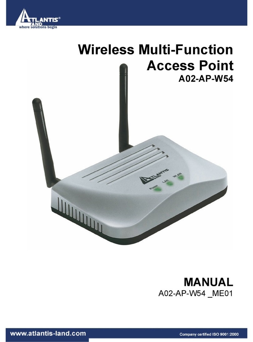
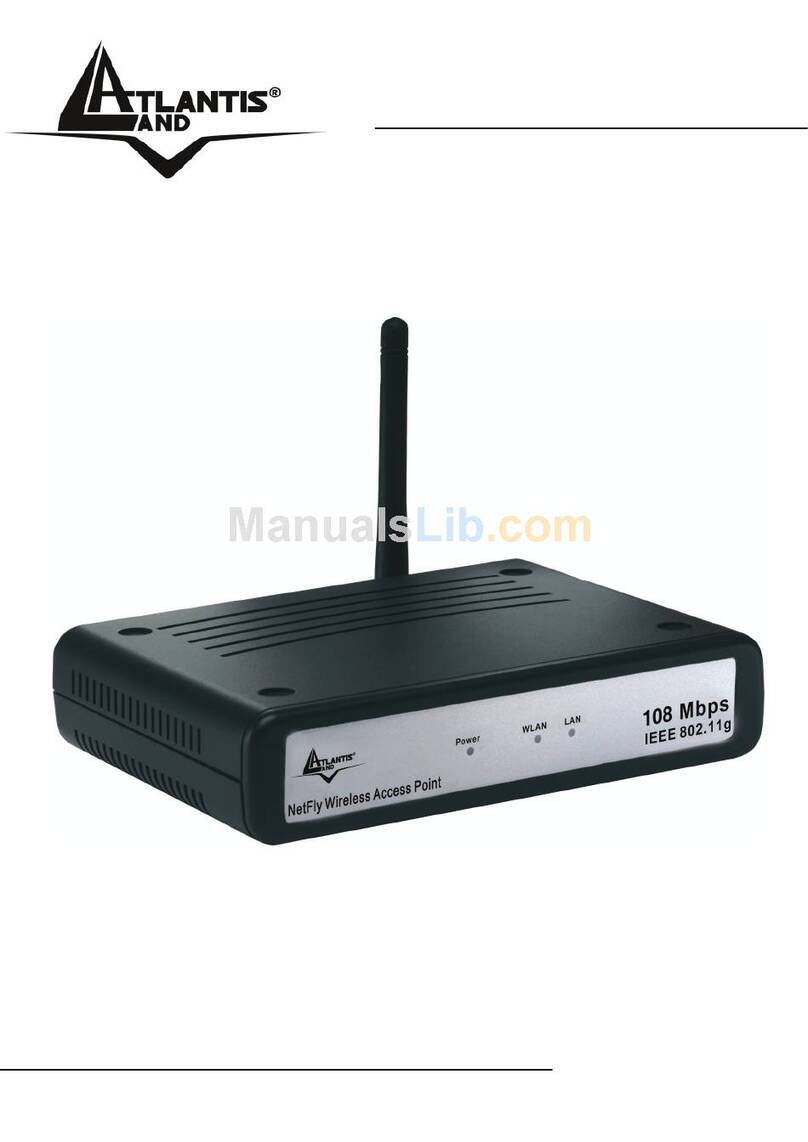
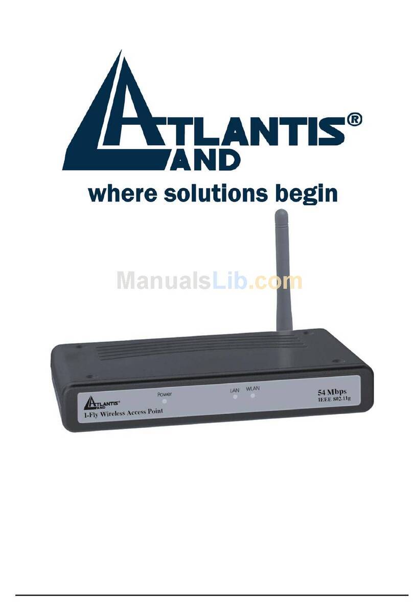
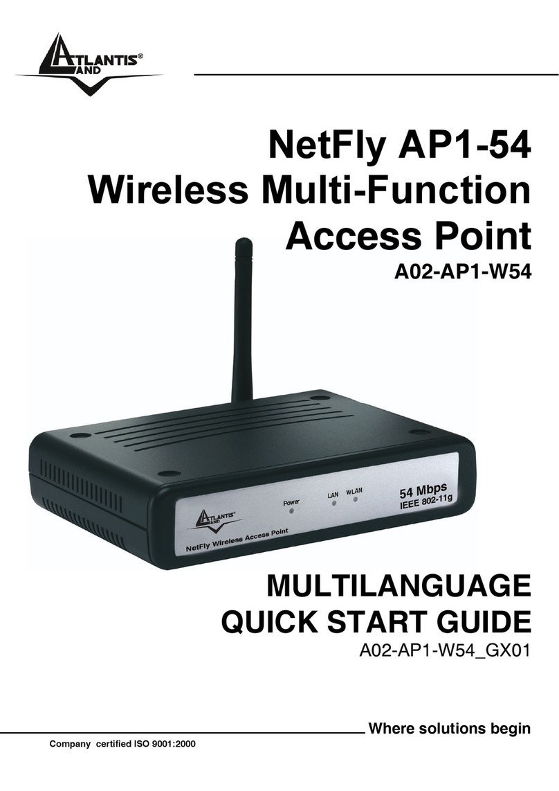
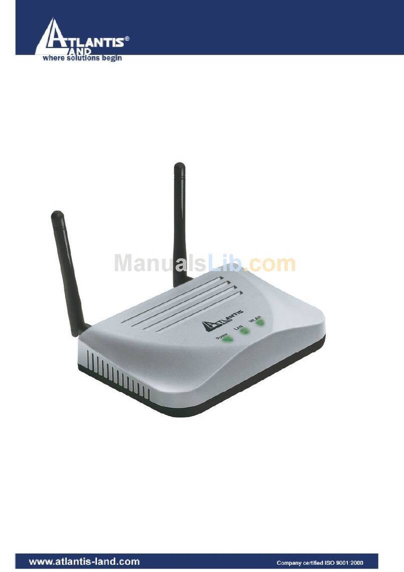
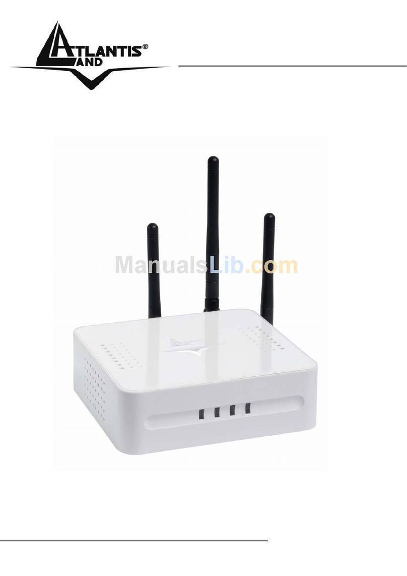
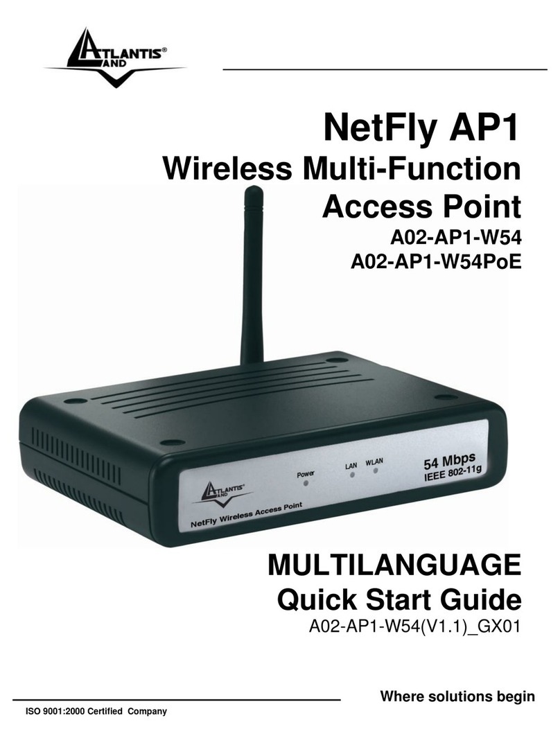
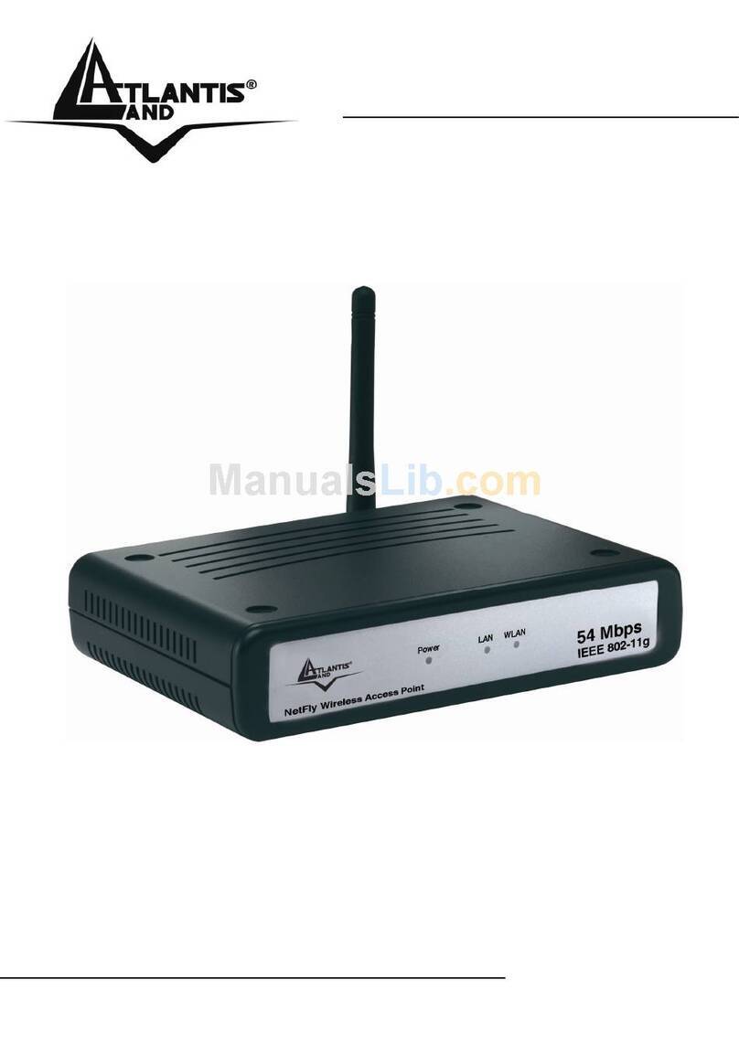
Atlantis Land NetFly AP1-54/P User manual


2
INDEX
1. CHAPTER 1: Introduction.....................................................................7
1.1 An Overview of the del Wireless Multi-Function Access Point...........7
1.2 Package Contents.........................................................................8
1.3 Wireless Multi-Function Access Point Features................................8
1.4 System Requirements ...................................................................9
1.5 Setup 9
1.6 Location 11
2. CHAPTER 2: Using Wireless Access Point ............................................12
2.1 Cautions for using the Wireless Access Point ................................12
2.1 Front panel and LEDs .................................................................13
2.3 Rear Panel and ports ..................................................................14
2.4 Cabling and setup.......................................................................15
3. CHAPTER 3: Configuration .................................................................16
3.1 Before Configuration...................................................................16
3.1.1 Windows 2000....................................................................17
3.1.2 Windows XP .......................................................................17
3.1.3 Windows VISTA..................................................................17
3.2 Default Settings..........................................................................19
3.2.1 Password ...........................................................................19
3.2.2 LAN and WLAN..................................................................19
3.3 Accessing the Access Point Web Configurator...............................20
3.3.1 Navigating the Access Point Web Configurator......................21
3.4 Wizard 22
3.5 Status 25
3.6 Basic Settings.............................................................................27
3.6.1 Access Point.......................................................................28
3.6.2 Client Mode........................................................................31
3.6.3 Repeater............................................................................33
3.6.4 WDS ..................................................................................36

3
3.6.5 AP+WDS mode ..................................................................46
3.7 IP Settings .................................................................................48
3.8 Advanced Settings......................................................................50
3.9 Security 52
3.10 Tools 54
APPENDIX A: Troubleshooting ...............................................................56
A.1 Using LEDs to Diagnose Problems ..........................................56
A.1.1 LED Power .........................................................................56
A.1.2 LED LAN ............................................................................56
A.1.3 LED WLAN .........................................................................57
A.2 WEB.....................................................................................57
A.3 Login....................................................................................57
A.4 FAQ......................................................................................59
APPENDIX B: Regolation........................................................................62
APPENDIX C: Technical Features............................................................63
APPENDIX D: Support ...........................................................................64
A02-AP1-W54(P)(v1.2)_ME01 (v1.2 March 2009)

4
Copyright Statement
No part of this publication may be reproduced, stored in a retrieval system, or
transmitted in any form or by any means, whether electronic, mechanical,
photocopying, recording or otherwise without the prior writing of the publisher.
Windows™ 98SE/2000/ME/XP/VISTA are trademarks of Microsoft® Corp. Pentium is
trademark of Intel. All copyright reserved.
The Atlantis Land logo is a registered trademark of Atlantis Land. All other names
mentioned mat be trademarks or registered trademarks of their respective owners.
Subject to change without notice. No liability for technical errors and/or omissions.
Wireless LAN, Health and Authorization for use
Radio frequency electromagnetic energy is emitted from Wireless LAN devices. The
energy levels of these emissions however are far much less than the electromagnetic
energy emissions from wireless devices like for example mobile phones. Wireless LAN
devices are safe for use frequency safety standards and recommendations. The use of
Wireless LAN devices may be restricted in some situations or environments for
example:
On board of airplanes, or
In an explosive environment, or
In case the interference risk to other devices or services is perceived or
identified as harmful
In case the policy regarding the use of Wireless LAN devices in specific organizations
or environments (e.g. airports, hospitals, chemical/oil/gas industrial plants, private
buildings etc.) is not clear, please ask for authorization to use these devices prior to
operating the equipment.
Regulatory Information/disclaimers
Installation and use of this Wireless LAN device must be in strict accordance with the
instructions included in the user documentation provided with the product. Any
changes or modifications made to this device that are not expressly approved by the
manufacturer may void the user’s authority to operate the equipment. The
Manufacturer is not responsible for any radio or television interference caused by
unauthorized modification of this device, of the substitution or attachment.
Manufacturer and its authorized resellers or distributors will assume no liability for any
damage or violation of government regulations arising from failing to comply with
these guidelines.

5
CE Mark Warning
In a domestic environment, this product may cause radio interference, in which case
the user may be required to take adequate measures.
CE in which Countries where the product may be used freely:
Germany, UK, Italy, Spain, Belgium, Netherlands, Portugal, Greece, Ireland, Denmark,
Luxembourg, Austria, Finland, Sweden, Norway and Iceland.
France: except the channel 10 through 13, law prohibits the use of other channels.
CE/EMC Restriction of Liability
The product described in this handbook was designed, produced and approved
according to the EMC-regulations and is certified to be within EMC limitations.
If the product is used in an uncertified PC, the manufacturer undertakes no warranty
in respect to the EMC limits. The described product in this handbook was constructed,
produced and certified so that the measured values are within EMC limitations. In
practice and under special circumstances, it may be possible, that the product may be
outside of the given limits if it is used in a PC that is not produced under EMC
certification. It is also possible in certain cases and under special circumstances,
which the given EMC peak values will become out of tolerance. In these cases, the
user himself is responsible for compliance with the EMC limits.
Declaration of Conformity
This equipment has been tested and found to comply with Directive 1999/5/CE of the
European Parliament and of the Council on radio equipment and telecommunications
terminal equipment and the mutual recognition of their conformity. After assessment,
the equipment has been found to comply with the following standards: EN 300.328
(radio), EN 301 489-1, EN 301 489-17 (electromagnetic compatibility) and EN 60950
(safety). This equipment may be used in all European Union contries and in all
countries applying Directive 1999/5/CE, without restriction, with the exception of the
following countries:
France (FR):
When this equipment is used outdoors, output power is limited to within
the frequency bans listed on the chart. For more info, consult the website
www.art-
telecom.fr.
Location
Frequency Band (MHz)
Power (EIRP)
Indoor (no restriction)
2400-2483,5
100mW(20dBm)

6
Outdoor
2400-2454
2454-2483,5
100mW(20dBm)
10mW(10dBm)
Italy(IT):
For more info, consult the website
www.comunicazioni.it
Luxembourg:
General authorization requie for network and service supply.
Norway (NO):
This subsection does not apply for geographical area within a radius
of 20 km from the center of Ny Alesund.
Russia (CCP):
only for indoor application.
Declaration of Conformity
Hereby, Sidin SpA, declares that this product is in compliance with the essential
requirements and other relevant provisions of Directive “Electromagnetic
Compatibility” and 1999/5/CE within CE Marking Requirememnt.
After assessment, the equipment has been found to comply with the following
standards:
EN60950-1:2001+ A11:2004 [Safety, R&TTE]
EN 50385
EN 301 489-17 1.2.1 (August 2002) [EMC]
EN 300 328 V1.6.1 (November 2004) [Radio SPectrum]
EN 301 489-1 V1.6.1 (2004)
CE Declaration is available on the web site www.atlantis-land.com.

7
1. CHAPTER 1: Introduction
Congratulations on your purchase of this IEEE 802.11g Wireless LAN Access Point. This
manual helps to features the innovating wireless technology that can help you build a
wireless network easily! This manual contains detailed instructions in operation of this
product. Please keep this manual for future reference.
With a WLAN (IEEE 802.11g) Access Point, a mobile computer can share data with
another mobile computer in a wireless way. Easy-to-use utilities are bundled with
WLAN Access Point for configuration and monitoring purposes.
WLAN networking can wirelessly transmit and receive data, minimizing the need for
wired connections, at a speed of up to Fifty-four megabit per second. With WLAN
networking, you can locate your PC wherever you want without wires and cables.
WLAN networking provides users with an access to real-time information anywhere in
their organization. The mobility provides productivity and service, which are not
available under wired networks.
1.1 An Overview of the del Wireless Multi-Function Access Point
The device for a total freedom of movement without losing the connection. Easy to be
installed and fast and flexible, with Wireless Multi-Function Access Point there is no
more obligation for a fixed working place: you can easily work or navigate for fun from
your own garden or in different rooms of your office, always in wireless connection.
The Roaming function gives you a complete freedom of movement and two or more
Wireless Multi-Function Access Point can serve wireless also large headquarters.
A pair of Wireless Multi-Function APs operating under Bridge mode to act as the bridge
that connect two Ethernet networks or Ethernet enabled clients together. Repeat Mode
is able to extend the effective range and coverage of the wireless network. Last but
not least the AP will be a wireless Ethernet adapter transforms any Ethernet-enabled
devices to have the wireless function.
Thanks to advanced security functions which are integrated and thanks to the
troughput of the protocol IEE802.11G you are going to have a fast and flexible
wireless net, hacker safe.
The chipsets fully support Wi-Fi Protected Access (WPA/WPA2) and the IEEE802.11i
draft security standards in hardware and high-speed encryption engines with no
performance degradation.

8
1.2 Package Contents
Unpack the package and check all the items carefully. If any item contained is
damaged or missing, please contact your local dealer as soon as possible. Also, keep
the box and packing materials in case you need to ship the unit in the future. The
package should contain the following items:
Wireless Access Point
1 x 2.2 dBi Antenna
CAT 5 (RJ45) cable
Quick Start Guide (English, Italian and French)
CDRom with online manual
AC/DC power adapter AC-DC (7.5 V, 1A)
1.3 Wireless Multi-Function Access Point Features
Wireless Multi-Function Access Poin provides the following features:
IEEE 802.11g and IEEE 802.11b: With built-in 802.11g access point for
extending the communication media to WLAN while providing the WEP and
WPA for securing your wireless networks.
Wi-Fi Protected Access (WPA) and WEP encryption: Thanks to
advanced security functions which are integrated and thanks to the
troughput of the protocol IEE802.11G you are going to have a fast and
flexible wireless net, hacker safe. The chipsets fully support Wi-Fi
Protected Access (WPA) and the IEEE 802.11i draft security standards in
hardware and high-speed encryption engines with no performance
degradation.
WDS: A pair of Wireless Multi-Function APs operating under Bridge mode
to act as the bridge that connect two Ethernet networks or Ethernet
enabled clients together. Repeat Mode is able to extend the effective range
and coverage of the wireless network.
1 Antenna: 1 x 2 dBi Dipole detachable Antenna1 (SMA)
1 port Fast Ethernet: A fast Ethernet 10/100Mbps port is supported in
the LAN site and automatic switching between MDI and MDI-X for 10Base-
T and 100Base-TX ports is supported. An Ethernet straight or cross-over

9
cable can be used directly, this fast Ethernet switch will detect it
automatically.
Mac Filtering (ACL): Access Control function allows clients whose MAC
addresses in the list will be able to connect to this Access Point.
Web based GUI: supports web based GUI for configuration and
management. It is user-friendly with an on-line help, providing necessary
information and assist user timing. It also supports remote management
capability for remote users to configure and manage this product.
Firmware Upgrade : the device can be upgraded to the latest firmware
through the WEB based GUI.
1.4 System Requirements
Before installing the device, your PC should meet the following:
Intel® Pentium®III 600Mhz or compatible processor with TCP/IP stack
Iinternet Explorer V6.0 on Netscape V6.0
CDRom
1.5 Setup
The setup of the Wireless Access Point can be performed using the following steps:
Visually inspect the Ethernet RJ45 port connector and make sure that it is
fully plugged in to the system’s Ethernet switch/hub port.
Fix the direction of the antennas. Try to place the AP in a position that can
best cover your wireless network. Normally, the higher you place the
antenna, the better the performance will be. The antenna’s position
enhances the receiving sensitivity.
Visually inspect if the Power Adapter was fully plugged to the device power
jack.

10

11
1.6 Location
Locate an optimum location for the Wireless LAN Access Point (AP). The best place for
your AP is usually the center of your wireless network, with line of sight to all of your
mobile stations.
Try to place the AP in a position that can best cover your wireless network. Normally,
the higher you place the antenna, the better the performance will be. The antenna’s
position enhances the receiving sensitivity.

12
2. CHAPTER 2: Using Wireless Access Point
2.1 Cautions for using the Wireless Access Point
Do not place the Wireless Access Point under high humidity and high
temperature.
Do not use the same power source for Wireless Access Point with other
equipment.
Do not open or repair the case yourself. If the Wireless Access Point is too hot,
turn off the power immediately and have a qualified serviceman repair it.
Place the Wireless Access Point on a stable surface.
Only use the power adapter that comes with the package.
Do NOT upgrade firmware on any Atlantis Land product over a wireless
connection. Failure of the device may result. Use only hard-wired network
connections.

13
2.1 Front panel and LEDs
LED
MEANING
POWER
This indicator lights green when the hub is receives
power, otherwise it is off.
WLAN
This indicator lights green when there are wireless devices
connected and transmitting data to the Wireless Access
Point.
LAN
These indicators light green when the LAN ports were
connected successfully.
These indicators blink green while the LAN ports were
transmitting data.

14
2.3 Rear Panel and ports
PORT
MEANING
POWER Jack
Connect the supplied power adapter to this jack.
LAN
Connect an UTP Ethernet cable to one of the four
LAN ports when connecting to a PC or an
office/home network of 10Mbps or 100Mbps.
Reset
After the device has turned on, press (5 seconds)
it to reset the device or restore to factory default
settings. Use a pin-shape item to push to reset
this device to factory default settings. It will be
useful too when the manager forgot the password
to login, but the setting will be back to default
setting.
Reverse SMA
There is one 2dBi Gain Antenna in the rear panel
for wireless connection.

15
2.4 Cabling and setup
Connect to the Switch/Hub
Plug in one end of the RJ45 network cable to the Switch/Hub port,
Plug in the other end of the RJ45 network cable to the Wireless Access Point.
Check the installation
The LEDs of the Access Point are clearly visible and the status of the network link can
be seen instantly:
With the power source on, once the device is connected, the Power, LAN and WLAN
port LEDs will light up indicating a normal status.
If the LAN Port’s Link indicator does not light up then check the RJ-45 cable if it is
firmly feed to the RJ45 port, while the LAN is link up to the Switch/Hub, the LAN port’s
LED will light up.

16
3. CHAPTER 3: Configuration
The Wireless Access Point has a Web GUI interface for the configuration. The AP can
be configured through the Web Browser. A network manager can manage, control and
monitor the AP from the local LAN. This section indicates how to configure the AP to
enable its functions.
3.1 Before Configuration
This section describes the configuration required by LAN-attached PCs that
communicate with the Wireless Access Point, either to configure the device or for
network access. These PCs must have an Ethernet interface (or wireless adapter)
installed properly, be connected to the Wireless Access Point either directly or through
an external repeater hub or by wireless, and have TCP/IP installed and configured with
a fixed IP address that must be in the same subnet of the Wireless Access Point. The
default IP address of the Wireless Access Point is 192.168.1.1 and subnet mask is
255.255.255.0.
Please follow the steps below for PC’s network environment installation. First of all,
please check your PC’s network components. The TCP/IP protocol stack and Ethernet
network adapter must be installed. If not, please refer to MS Windows related
manuals.
Any TCP/IP capable workstation can be used to communicate
with or through the Wireless Access Point to configure other
types of workstations, please consult the manufacturer’s
documentation.

17
3.1.1 Windows 2000
1. Go to Start / Settings / Control Panel. In the Control Panel, double-click on
Network and Dial-up Connections.
2. Double-click LAN Area Connection.
3. In the LAN Area Connection Status window, click Properties.
4. Select Internet Protocol (TCP/IP) and click Properties.
5. Select Use the Following IP Address (EG IP=192.168.1.2 and subnet
Mask=255.255.255.0).
6. Click OK to finish the configuration.
3.1.2 Windows XP
1. Go to Start / Control Panel (in Classic View). In the Control Panel, double-
click on Network Connections.
2. Double-click Local Area Connection.
3. In the LAN Area Connection Status window, click Properties.
4. Select Internet Protocol (TCP/IP) and click Properties.
5. Select the Use the following IP address radio button (EG IP=192.168.1.2
and subnet Mask=255.255.255.0).
6. Click OK to finish the configuration
3.1.3 Windows VISTA
1. Go to Start -> Control Panel (in Classic View). In the Control Panel, double-
click on Network and Sharing Center icon.
2. Click Manage Network connections then double-click Local Area
Connection and click Properties.
3. Click Continue (Windows needs your permission to continue).

18
4. Select Internet Protocol Version 4 (TCP/IP) and click Properties.
5. Select the Use the following IP address radio button (EG IP=192.168.1.2
and subnet mask=255.255.255.0)
6. Click OK to finish the configuration.

19
3.2 Default Settings
Before configuring the Wireless AP through WLAN, make sure that the SSID, Channel
and the WEP was set properly.
The default setting of the Wireless AP that you will use:
User: admin
Password: admin
IP Address: 192.168.1.1
Subnet Mask: 255.255.255.0
Wep Encryption: disable
SSSID: default
Channel:6
3.2.1 Password
When there is a screen needs to enter the Network password, it means that there is a
password settle, type in the password you entered before.
3.2.2 LAN and WLAN
The parameters of LAN and WLAN ports are pre-set in the factory. The default values
are shown below.
LAN Port
WLAN Port
IP address
192.168.1.1
Channel=6
SSID=default
Encryption=none
Subnet Mask
255.255.255.0

20
3.3 Accessing the Access Point Web Configurator
Before you configure this device, note that when the AP is configured through an
Ethernet connection, make sure the manager PC must be set on same the IP
network. For example, when the default network address of the default IP address of
the AP is
192.168.1.1
, then the manager PC should be set at 192.168.1.x (where x is
a number between 2 and 254), and the default subnet mask is 255.255.255.0.
Open Internet Explorer 5.0 or above Web browser.
Enter IP address
http://192.168.1.1
(the factory-default IP address setting) to the
address location.
When there is a screen needs to enter the User name and Password, both of the
default Username and Password is “admin”.
Click OK.
The screen will show the station summary of the AP when you login to the AP.
Other manuals for NetFly AP1-54/P
1
Table of contents
Other Atlantis Land Wireless Access Point manuals

Atlantis Land
Atlantis Land I-Fly A02-WAP-54G User manual

Atlantis Land
Atlantis Land FlyBoost CL100 User manual

Atlantis Land
Atlantis Land A07-WA6102X-2 User manual

Atlantis Land
Atlantis Land A02-AP2-W54M User manual

Atlantis Land
Atlantis Land I-Fly i I-Fly Wireless Access Point User manual

Atlantis Land
Atlantis Land A02-AP1-W54 User manual

Atlantis Land
Atlantis Land A02-AP-W54 User manual

Atlantis Land
Atlantis Land A02-AP2-W54M User manual

Atlantis Land
Atlantis Land NETFLY AP2-54M User manual

Atlantis Land
Atlantis Land NetFly WAP 108 A02-WAP-54G(V1.1)_GX01 User manual