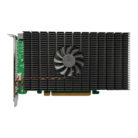
Datatek DT-6061 User manual

DT-6061
USER’S MANUAL
IP-PAD A
PPLICATION
VERSION 1.0.16
721 Route 202-206
Bridgewater, NJ 08807
fax: 908.218.1736
phone: 908.218.0500
email: sales@datatekcorp.com
http://www.datatekcorp.com

'7,33$'$SSOLFDWLRQ 8 VHUV0DQXDO
11/01/00 Datatek Applications Inc. 2

'7,33$'$SSOLFDWLRQ 8 VHUV0DQXDO
11/01/00 Datatek Applications Inc. 3
CONTENTS
1 INTRODUCTION.....................................................................................................................4
1.1 DT-6061 WITH IP-PAD APPLICATION (TYPICAL CONFIGURATION)...........................................4
1.2 APPLICATION SPECIFICATIONS ...............................................................................................5
1.3 APPLICATION BASIC ARCHITECTURE & OPERATION.................................................................5
1.4 IP-PAD APPLICATION CONFIGURATION..................................................................................6
2 APPLICATIONS COMMANDS...............................................................................................7
2.1 INPUT CONVENTIONS.............................................................................................................7
2.2 LOGIN ...................................................................................................................................7
2.3 LOGOUT................................................................................................................................7
3 APPLICATION SOFTWARE INSTALLATION & UPGRADE ..............................................12
4APPENDIX A – IP-PAD MEASUREMENTS AVAILABLE...................................................13
5 SUPPORT FOR X.3 PAD PARAMETER VALUES..............................................................14
6 WARRANTY..........................................................................................................................16

'7,33$'$SSOLFDWLRQ 8 VHUV0DQXDO
11/01/00 Datatek Applications Inc. 4
1 INTRODUCTION
The IP-PAD Application eliminates the need, complexity, or expense of specialized X.25
equipment and allows any available port on a DT-4000, DT-2020 connected SAM, or BNS
endpoint such as a SAM port, to be used for Network Element (NE) access.
The IP-PAD Application of the DT-6061 allows an X.25 device to be connected to a synchronous
port anywhere in the network. Supporting both X.3 PAD and Pass-Through functionality on a per
virtual circuit basis, IP-PAD Application connections to virtual circuits on an X.25 port are
provided with a telnet TCP/IP connection.
The following diagram depicts a configuration of BNS network elements and non-BNS network
elements with BNS/non-BNS hosts that require access to those network elements.
1.1 DT-6061 WITH IP-PAD APPLICATION (TYPICAL CONFIGURATION)
S A M
Node
T
R
K
T
S
M
X.25
X.25
Network Element
NE
C
P
MFiber
X.25
IP
Network
DT-6061
DT-4000
IP IP
IP
BNS Host
IP
IP Hosts
Network Elements
U
M
I
In the above configuration, there is one circuit carrying X.25 LAPB frames from the DT-6061 to a
DT-4000 connected Network Element (NE) or a SAM connected NE. The X.25 Network Element
may be anywhere on the available networks
(both BNS and IP)
as the above diagram depicts
.
IP
Hosts access the virtual circuits on these Network Elements via a TCP port number. BNS Hosts

'7,33$'$SSOLFDWLRQ 8 VHUV0DQXDO
11/01/00 Datatek Applications Inc. 5
access the virtual circuit via the UMI1. The same is true of terminal and PC devices on either the
BNS or the IP network.
1.2 APPLICATION SPECIFICATIONS
Number of X.25 devices per DT-6061 30+
Number of Virtual Circuits per X.25 Device 1-100
PAD Service Yes (Per Virtual Circuit)
X.25 Pass-Through Service Yes (Per Virtual Circuit)
Number of OA&M Channels available One per X.25 device.
Measurements Available LAPB, Packet Layer PAD, Byte Counts,Error Counts
Alarms Yes
SNMP (DT-6061 Agent) Yes
1.3 APPLICATION BASIC ARCHITECTURE & OPERATION
1.3.1 INTERFACE TYPES
There are three distinct interface types on the IP-PAD application.
The Configuration Circuits
This interface type is used for configuration and administration of the IP-PAD application for a
particular X.25 connection via Telnet.
The Virtual X.25 Line Circuits
For this interface type, one virtual X.25 line is configured to receive on a TCP Port. This TCP port
will then listen for the TCP call from the DT-4000, UMI, etc. The specific TCP port used is the
configured base + 0.
The X.25 VCC (via X.3 PAD) Circuits.
For this interface type, one TCP port is configured per VCC on the X.25 line. These TCP ports will
listen for a call from an endpoint that requires access to the VCC. The specific TCP ports used
begin at the configured base + 1 for X.25 VCC 1, and increment in proportion.
1.3.2 CIRCUIT USAGE EXAMPLE
The IP-PAD application would have its X.25 line, and per circuit configuration entered. This
includes the base TCP port number that establishes the range of TCP ports relating to that X.25
line.
Once restored to service, the X.25 line TCP port (offset 0 from the base) listens for in inbound call
from a DT-4000, UMI, or DT-2020/SAM port. This establishes the connectivity with the remote
X.25 network element endpoint.
The VCC TCP ports (offset 1 – Number of Virtual Circuits) will listen on their respective TCP ports
for inbound calls as well. Any host, or other IP endpoint, may make a telnet call to these TCP
ports for per virtual circuit connectivity to the X.25 network element.
1The UMI allows both synchronous and asynchronous endpoints connected to a BNS network to access
endpoints on an IP network. Similarly, endpoints on an IP network can access both synchronous and
asynchronous endpoints on a BNS network.

'7,33$'$SSOLFDWLRQ 8 VHUV0DQXDO
11/01/00 Datatek Applications Inc. 6
1.4 IP-PAD APPLICATION CONFIGURATION
The configuration of the X.25 application takes place on its OA&M port. That is TCP port number
10000 + its instance number in the DT-6061.
The configuration required for the IP-PAD application is:
•
Per application:
This is the TCP port number to be used as a base for a range of TCP ports
the application instance shall use. The synchronous transport to the X.25 network element
occurs at offset zero to this base TCP port number. The individual X.25 virtual circuits are
identified by the base TCP port number plus the X.25 virtual circuit port number.
•
Per X.25 line:
These consist the LAPB transmission window size and other link layer
parameters.
•
Per X.25 VCC:
These consist of the PAD profile associated with the VCC, the window size to
be used for transmission in the X.25 packet layer, and other parameters associated on a per
virtual circuit basis.
The Per X.25 Line Configuration parameters are as follows:
Parameter Values Default Units
X.25 Logical Line Type2DTE, DCE DCE
Number of X.25 VCs 16
Default Max Packet Size3128, 256 256 Bytes
LAPB Tx Window Size 1-7 2 Frames
Waiting ACK Time (T1) 1-60 3 Seconds
Maximum Attempts to complete a Transmission
(N2) 1-255 7 Seconds
Action when N2 Count Exceeded4Disc, reset. Reset
Action when DISC received5Disc, reset. Reset
The per VCC configuration parameters are as follows:
Parameter Values Default Units
Packet Layer Window 1-7 2 Packets
PAD Inactivity Timer (T) 2-20, OFF OFF Seconds
Profile ID Value, Transparent Transparent
2The IP-PAD application currently supports only the DCE end of the X.25 connection. All
Network Elements known to date are DTE.
3The 1980 standard provided for 128 byte packet sizes. The 1984 standard increased the
maximum size to 256 bytes. Later standards have optionally increased that number. However,
nearly all implementations of X.25 follow the 1984 standard, and it is considered the default for all
implementations known to date.
4The IP-PAD application currently supports only X.25 PVCs. As such a DISC action is not
defined.
5Receipt of a DISC on an X.25 PVC is not valid. This is not currently supported.

'7,33$'$SSOLFDWLRQ 8 VHUV0DQXDO
11/01/00 Datatek Applications Inc. 7
2 APPLICATIONS COMMANDS
The DT-6061 software is composed of two components. One component, called the
Platform,
exists to support all applications. The second component is comprised of the individual
application
(s)
.
The
Platform
provides Operating System functions, selected interfaces, protocol stacks, SNMP
functions, and system OA&M while each application uses the services of the resident
Platform
.
2.1 INPUT CONVENTIONS
All parameters may be given on the command line. Parameters of the form name=<value> may
be given in any order.
For several complex commands, listed below, missing parameters, or corrections of errors in
given parameters, of the form name=<value> are collected by prompting the console user. The
user responds to a prompt for the name by typing the required <value> followed by
newline
.
Defaults are supplied in some cases, so the user need only enter
newline
.
q
Commands may be entered in upper or lower case.
q
Parameters of the form name=value may use upper or lower case for name.
q
Default values, if any, are shown in parenthesis as part of the prompt.
q
Case is preserved for values.
q
When a password is being requested by a prompt, input is not echoed.
q
Backspace erases one character and @deletes the current line of input. Most commands are
killed by del key.
2.2 LOGIN
Syntax: login PASSWD=<password>
(The default password is “initial”)
The login command is used to allow access to the other configuration commands.
The PASSWD parameter is not echo suppressed. However, if the PASSWD parameter is not
provided, the console prompts for a password; the response
is
echo-suppressed in this case.
If the password is valid, the user is placed in the
logged in
mode. Once the console user is logged
in
, the balance of the commands are accessible.
Note: Every application instance might be assigned a different password.
2.3 LOGOUT
Syntax: logout
The logout command is only allowed if the console user is logged
in
. It uses no arguments. It will
set the console to the logged
out
mode. The console may also be logged out by typing
exit
or
ctrl-D
.
Passwords are up to seven characters in length. The characters are alphanumeric and special
characters are not allowed.

'7,33$'$SSOLFDWLRQ 8 VHUV0DQXDO
11/01/00 Datatek Applications Inc. 8
2.3.1 HELP
Syntax: help
The help command is always visible. The help command displays the currently allowed
commands for the mode that the unit is currently entered.
2.3.2 VERSION
Syntax: ver
The version command is only visible when the application is
logged in
. The command has no
arguments. It displays the current software and database revisions of the application.
2.3.3 PLACING COMPONENTS IN SERVICE
Syntax: rs <link | <vc XXX>>
The restore command is only visible when the application is
logged in
. The command is used to
place the X.25 Link, or any of the X.25 virtual circuits, into service. A TCP connection is not
available until the component is placed into service.
At least one argument is required. That argument is the component type to be placed into service.
There is only a single X.25 link, and multiple X.25 virtual circuits on that link which may be
individually brought into service.
Once the component is brought into service, it will await a TCP session if the connection type is
rcv. If the connection type is orig, a TCP session will be established with the endpoint specified
in the component configuration. Please see the sections that follow for configuration of both the
link, and the virtual circuits.
2.3.4 TAKING COMPONENTS OUT OF SERVICE
Syntax: rm <link | <vc XXX>>
The remove command is only visible when the application is
logged in
. The command is used to
place the X.25 Link, or any of the X.25 virtual circuits, out of service. Any TCP connection using
those components is automatically taken down when the component is removed from service.
At least one argument is required. That argument is the component type to be removed from
service. There is only a single X.25 link, and multiple X.25 virtual circuits on that link which may
be individually removed from service.
2.3.5 CONFIGURING GENERAL & LINK PARAMETERS
Syntax: link [base=<TCP Port#>] [type=<RCV|ORIG>] [dest=<IP Address>]
[dport=<TCP Port>] [numvcc=<#VCC>] [win=<#>] [T1=<#>] [N2=<#>]
The link command is only visible when the application is logged in. The command is used to
configure a Virtual X.25 line termination.
The base parameter is the TCP port number base at which the X.25 line, and the associated
X.25 virtual circuits, are to be IP terminated. The default is computed as follows:
Default TCP Base=((<Application Instance# > -1)*200)+30000
For example, instance #1 of the application will have its base address at 30000. The X.25 link
would be connected at that TCP port number. The first VC would be at TCP 30001, and so on.
When the X.25 link is to be on an incoming TCP session, the type would be set to rcv. The X.25
link would reside at the TCP port specified by the base parameter.

'7,33$'$SSOLFDWLRQ 8 VHUV0DQXDO
11/01/00 Datatek Applications Inc. 9
When the X.25 link is to be on an outgoing TCP session, the type would be set to orig. The IP
address would be specified by the dest parameter, and the TCP port at that IP address would be
specified by the dport parameter.
The numvcc parameter is the number of X.25 virtual circuits to be supported. The default is 16.
The win parameter specifies the LAPB window size to be used for transmission. The Window
size is always 8 frames for receive. The default transmission window size is 2 per the ITU
specification X.25.
The t1 parameter specifies the value of the T1 timer. The timer defaults to the recommendation of
the ITU specification X.25. It is provided as an option for non-standard configurations.
The n2 parameter specifies the value of the N2 retry counter. The value defaults to the
recommendation of the ITU specification X.25. It is provided as an option for non-standard
configurations.
2.3.6 VIRTUAL CIRCUIT CONFIGURATION
Syntax: vc <vc#> [win=<#>] [svc=< pad|pass>] [type=<RCV|ORIG>]
[dest=<IP Address>] [dport=<TCP Port>]
The VC command is only visible when the application is logged in. The command is used to
configure a virtual circuit connection to a Virtual X.25 line.
The <VC#> parameter refers to the virtual circuit configured on the X.25 line. It has the range of 1
through the number of circuits configured.
When the X.25 virtual circuit is to be placed on an incoming TCP session, the type would be set
to rcv. The X.25 virtual circuit would reside at the TCP port specified by the base parameter
offset by its virtual circuit number.
When the X.25 virtual circuit is to be placed on an outgoing TCP session, the type would be set
to orig. The IP address would be specified by the dest parameter, and the TCP port at that IP
address would be specified by the dport parameter.
The win parameter refers to the packet layer window size to be used for transmission purposes.
It defaults to the value of 2 per the ITU Recommendation X.25.
The svc parameter allows the type of service to be performed on the virtual circuit. When the
value of PAD is selected, the virtual circuit is terminated in a X.3 PAD service. When the value of
PASS is selected, an X.25 pass-through service is selected.
2.3.7 CONFIGURING PAD PARAMETERS
Syntax: pad <vc #>[echo=<ON|OFF>] [fwd=< none|cr|all>] [idle=<#ticks>]
[break=<none|intr|reset|brkind>] [crlf=<none|rmt|vc|both>]
[inact=<# seconds>|OFF]
The PAD command is only visible when the application is logged in. The command is used to
configure the X.3 PAD parameters of a virtual circuit. These parameters have relevance only if
the service selected on the virtual circuit is
PAD.
The <VC #> parameter refers to the virtual circuit configured on the X.25 line. It has the range of
one through the number of circuits configured.
The echo option refers to reference #2 in the X.3 parameter list. When set to OFF, the IP-PAD
will not echo characters back to the IP endpoint. When set to the value of ON, all characters are
to be echoed back to the IP source.

'7,33$'$SSOLFDWLRQ 8 VHUV0DQXDO
11/01/00 Datatek Applications Inc. 10
The fwd parameter specifies reference #3 in the X.3 parameter list. This is the forwarding
condition (outside the PAD timer) which will forward data towards the X.25 virtual circuit. A value
of NONE indicates that there are no character forwarding conditions. A value of CR indicates that
a carriage return will forward any accumulated data (including the carriage return). A value of
ALL indicates that all data is to be forwarded immediately. The ALL option has the effect of
generating single user character X.25 packets on this virtual circuit.
The idle parameter refers to reference #4 in the X.3 parameter list. This is the time forwarding
condition. When it expires, it will forward any data collected to the X.25 circuit. The timer is reset
to the specified value whenever a forwarding condition is reached. The value is based on ticks of
1/20th of a second each per the X.3 specification.
The break parameter refers to reference #7 in the X.3 parameter list. This is the action to be
taken when a break indication (a standard telnet encapsulated value) is received from the remote
IP endpoint. The value of NONE will ignore the break, and it is deleted from the data stream. The
value of INTR will generate an X.25 interrupt packet. The value of RESET will generate an X.25
virtual circuit reset. The value of BRKIND will generate an X.29 “indication of break” message on
the X.25 virtual circuit.
The crlf parameter refers to reference #13 in the X.3 parameter list. This is the action to be taken
when a CR is received in the data stream from the remote IP endpoint. A value of NONE
indicates that there is to be no LF (line feed) insertion. A value of RMT will insert an LF following
a CR whenever it is sent towards the remote IP endpoint. A value of VC will insert an LF following
a CR whenever it is sent towards the X.25 virtual circuit. A value of BOTH will insert an LF
following a CR in either direction.
The inact option refers to the PAD inactivity timer. If enabled, the TCP session on that X.25
virtual circuit is disconnected when the inactivity timer expires. The value defaults to OFF.
2.3.8 DISPLAY MEASUREMENTS
Syntax: dmeas [link|vc <#>]
The dmeas command is only visible when the application is logged in. The command is used to
display the current measurements on either the X.25 link or per virtual circuit.
The LINK parameter will display the measurement information for the X.25 link being supported
by this instance of the application.
The VC <#> option will display the measurement information for a particular X.25 virtual circuit on
the link. The virtual circuit number is in the range of one through the maximum number supported
by the application.
2.3.9 VERIFY CONFIGURATION
Syntax: vfy [link|vc <#>]
The vfy command is only visible when the application is logged in. The command is used to
display the configured options on the X.25 link, or a virtual circuit resident on the X.25 link.
The LINK parameter will display the configuration information for the X.25 link being supported by
this instance of the application.
The VC <#> parameter will display the configuration information for a particular X.25 virtual circuit
on the link. The virtual circuit number is in the range of 1 through the maximum number supported
by the application.

'7,33$'$SSOLFDWLRQ 8 VHUV0DQXDO
11/01/00 Datatek Applications Inc. 11
2.3.10 DISPLAYING CURRENT CONNECTIONS
Syntax: dc
The dc command is used to display all of the current connections into the IP-PAD application.
This includes the X.25 link, and any X.25 virtual circuit connections. The command will issue a
report that shows the connection peer for each active connection.
2.3.11 SNOOPING X.25 TRAFFIC
Syntax: snoop [OFF | L2 | <VC#>]
The IP-PAD application has a diagnostic ability to snoop on either X.25 link at the LAPB layer, or
on an individual circuit at the packet layer. This is done with the snoop command. All output is
directed to the OA&M connection.
If the command is invoked with no arguments, it produces a report of all active snooper
configurations.
If the command is invoked with the OFF option, all of the snooper configurations are disabled.
If the command is invoked with the L2 option, the LAPB interface to the X.25 device is snooped.
Output is displayed on the OA&M session. Please note that this could be extensive for a
moderately busy X.25 line.
If the command is invoked with a virtual circuit number in the range of 1 through the maximum
number of X.25 circuits; the packet layer of the circuit specified is snooped.
2.3.12 RESTART X.25 OPERATION
Syntax: restart
The restart command is only visible when the application is logged in. The command is used to
manually initiate a protocol restart of the X.25 link and packet layers.

'7,33$'$SSOLFDWLRQ 8 VHUV0DQXDO
11/01/00 Datatek Applications Inc. 12
3 APPLICATION SOFTWARE INSTALLATION & UPGRADE
An application may be initially installed, or upgraded, using the install command.
Refer to the DT-6061 Platform User’s Manual and refer to the section titled: Application
Software Installation & Upgrade

'7,33$'$SSOLFDWLRQ 8 VHUV0DQXDO
11/01/00 Datatek Applications Inc. 13
4 APPENDIX A – IP-PAD MEASUREMENTS AVAILABLE
This appendix itemizes the measurements available using the
display measurements
(dmeas)
command. There are two options to the dmeas command. These are link and vc.
The link option provides X.25 Link level measurements, and the vc option provides per virtual
circuit measurements.
The base measurements are always displayed, and the error and exception counters are only
displayed if nonzero.
The link level measurements available are as follows:
Measurement Description Type
Number of LAPB Frames Received Base
Number of LAPB Frames Transmitted Base
Number of LAPB Bytes Received Base
Number of LAPB Bytes Transmitted Base
Number of Invalid Frames Received. Base
The per virtual circuit measurements available are as follows:
Measurement Description Type
Number of Packets Received from X.25 Link Base
Number of Packets Sent to X.25 Link Base
Number of Bytes Received from X.25 Link Base
Number of Bytes Sent to X.25 Link Base
Number of Call Request Packets Received Exception
Number of Call Accept Packets Received Exception
Number of Clear Request Packets Received Exception
Number of Clear Confirmation Packets Received Exception
Number of Interrupt Packets Received Exception
Number of Interrupt Confirm Packets Received Exception
Number of REJ Packets Received Exception
Number of RNR Packets Received Exception
Number of Reset Request Packets Received Exception
Number of Reset Confirmation Packets Received Exception

'7,33$'$SSOLFDWLRQ 8 VHUV0DQXDO
11/01/00 Datatek Applications Inc. 14
5 SUPPORT FOR X.3 PAD PARAMETER VALUES
The IP-PAD supports the relevant X.3 PAD parameters. Since the IP-PAD is not a physical
device, some of the parameters are not readily applicable. Responses via X.29 will carry default
values if queried.
The table below will indicate all the X.3 parameters, and the support of these parameters by the
IP-PAD application.
Ref
#Description Supported Options Note Config
1 PAD recall 0 – None User Command session
provided by Datakit CC or
DT-4000 or DT-2020.
No
2Echo 0–NoEcho
1 – Echo Yes
3Data Forwarding
Characters 0 – None
2 – CR
126 – All Characters
Yes
4 Idle Delay 0-255 Ticks are in 1/20th of a
second. Yes
5 Ancillary Device
Control 0 – None Configured on DT-4000 or
SAM/DT-2020 port
configuration
No
6 Control of PAD service
signals and PAD
command signals.
0 – No PAD service signals
are transmitted. DT-4000 or SAM is DTE
service center. No
7 Operation of PAD on
receipt of break from
IP
0 – Nothing
1 – Send X.25 Interrupt
2 – Send X.25 Reset
4 – X.29 “Indication of
Break”
Yes
8 Discard Output 0 – Normal Data Delivery No
9 Padding after CR 0 – No Padding after CR No
10 Line Folding 0 – No line folding No
11 Binary Speed 18 – 64000bps For Reporting Only No
12 Flow Control of the
PAD 0 – No use of X-ON
and X-OFF These are functions of the
DT-4000 and SAM devices. No

'7,33$'$SSOLFDWLRQ 8 VHUV0DQXDO
11/01/00 Datatek Applications Inc. 15
13 LineFeed Insertion
after CR 0 – No Linefeed Insertion
1 – Insert Linefeed after CR
towards IP.
2 – Insert Linefeed after CR
from IP
Yes
14 Padding after Linefeed 0 – No Padding after LF No
15 Editing 0 – No use of editing. User command session
performed via the DK CC,
the DT-4000, and the DT-
2020.
No
16 Character Delete None User command session
performed via the DK CC,
the DT-4000, and the DT-
2020.
No
17 Line Delete None User command session
performed via the DK CC,
the DT-4000, and the DT-
2020.
No
18 Line Display None User command session
performed via the DK CC,
the DT-4000, and the DT-
2020.
No
19 Editing PAD service
signals 0 - None No
20 Echo Mask 0 - None No
21 Parity 0 – No generation or
checking. Parity performed by DT-
4000 or SAM. No
22 Page Wait 0 - Disabled No
23 Input field size 0 - Undefined User command session
performed via the DK CC,
the DT-4000, and the DT-
2020.
No
24 End of Frame Signals 0 – Undefined Size EOF is determined and
encoded per the RFC since
this is an IP application.
No
25 Extended Data
Forwarding Signals 0 – No extended Data No
26 Display Interrupt 0 – No display interrupt No
27 Display Interrupt
Confirmation 0 – No display interrupt
confirmation. No
28 Diacritic Character
Coding 0 – Basic Coding No
29 Extended Echo Mask 0 – No Extended Echo Mask No

'7,33$'$SSOLFDWLRQ 8 VHUV0DQXDO
11/01/00 Datatek Applications Inc. 16
6 WARRANTY
The warranty period for hardware shall be one year from the date of delivery, and the warranty for
software shall be 90 days from the date of delivery. Replacements and repairs are guaranteed for
the longer of the remaining original warranty period or 90 days.
©Copyright 2000 Datatek Applications Inc.
All Rights Reserved
Printed in USA
Other manuals for DT-6061
1
Table of contents
Other Datatek Computer Hardware manuals

