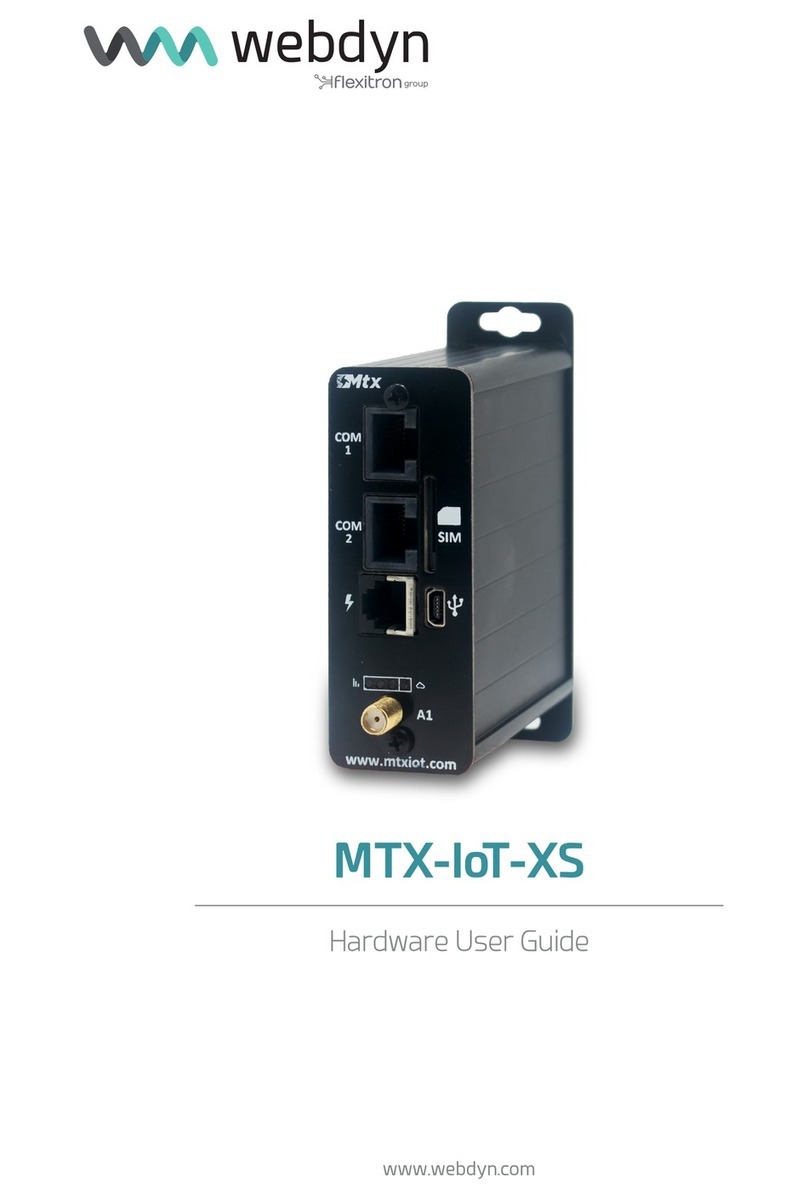
Flexitron webdyn MTX-StarEnergy-E Installation manual

MTX-StarEnergy-E
Hardware User Guide
www.webdyn.com

contact@webdyn.com | webdyn.com
V1.03 subject to changes | Webdyn © by Flexitron Group
2
Index
General Notes .................................................................................................................. 4
Important Information ..................................................................................................... 4
Warranty ........................................................................................................................... 5
Revision Information........................................................................................................ 5
Installation guide.............................................................................................................. 6
1. About this Guide ................................................................................................................................... 6
Safety Requirements and Protection Regulations ......................................................... 7
1. Safety Instructions................................................................................................................................ 7
2. General Precauciones .......................................................................................................................... 8
3. SIM Card Precautions........................................................................................................................... 8
4. Antenna Precautions ........................................................................................................................... 9
5. Radio Frequency (RF) Exposure and SAR .......................................................................................... 9
6. Personal Medical Devices ................................................................................................................... 10
Regulatory and Type Approval Information..................................................................... 11
1. Directives and Standards..................................................................................................................... 11
2. SAR Requirements Specic to Portable Mobiles................................................................................ 13
3. RoHS Statement ................................................................................................................................... 13
4. Disposal of Old Electrical and Electronic Equipment ......................................................................... 14
5. General Information ............................................................................................................................. 15
5.1 Package Contents .................................................................................................................... 15
5.2 Features.................................................................................................................................... 16
5.3 Specication Ratings ............................................................................................................... 16
5.4 Product Label Marking............................................................................................................. 17
6. Functional Description.......................................................................................................................... 18
6.1 LTE Functionality....................................................................................................................... 19
6.2 LED Status Indicators .............................................................................................................. 22
6.3 External Interfaces................................................................................................................... 24
6.4 Mains Power Supply Connection............................................................................................. 25
6.5 Antenna Connection ................................................................................................................ 26
6.6 SIM Card ................................................................................................................................... 26

contact@webdyn.com | webdyn.com
V1.03 subject to changes | Webdyn © by Flexitron Group
3
6.7 Reset Button............................................................................................................................. 27
6.8 USB ........................................................................................................................................... 27
6.9 RS232 DCE Connection........................................................................................................... 28
6.10 RS485 Connection................................................................................................................. 30
6.11 Cable Adapter to DB9 Male................................................................................................... 32
7. Installation............................................................................................................................................. 33
7.1 Installation Location................................................................................................................. 33
7.2 Modem Wall Mounting ............................................................................................................. 34
7.3 SIM Card Installation................................................................................................................ 37
7.4 Antenna Installation ................................................................................................................. 37
7.5 RS232/RS485 Cable Installation ........................................................................................... 38
7.6 AC Mains and DC Power Input Cable Installation................................................................... 38
7.7 Cover Cabling Space and Seal................................................................................................. 39
7.8 Power on LTE Modem and Check Operation .......................................................................... 40
Ofces & Support Contact............................................................................................... 42

contact@webdyn.com | webdyn.com
V1.03 subject to changes | Webdyn © by Flexitron Group
4
General Notes
Product is deemed accepted by recipient and is provided without interface to recipient’s products. The
documentation and/or product are provided for testing, evaluation, integration and information purposes.
The documentation and/or product are provided on an “as is” basis only and may contain deciencies or
inadequacies. The documentation and/or product are provided without warranty of any kind, express or
implied. To the maximum extent permitted by applicable law, Matrix Electronica S.L.U. further disclaims all
warranties; including without limitation any implied warranties of merchantability, completeness, tness
for a particular purpose and non-infringement of third-party rights. The entire risk arising out of the use or
performance of the product and documentation remains with recipient. This product is not intended for
use in life support appliances, devices or systems where a malfunction of the product can reasonably be
expected to result in personal injury. Applications incorporating the described product must be designed
to be in accordance with the technical specications provided in these guidelines. Failure to comply with
any of the required procedures can result in malfunctions or serious discrepancies in results. Furthermore,
all safety instructions regarding the use of mobile technical systems, including GSM products, which also
apply to cellular phones, must be followed. Matrix Electronica S.L.U. or its suppliers shall, regardless of
any legal theory upon which the claim is based, not be liable for any consequential, incidental, direct,
indirect, punitive or other damages whatever (including, without limitation, damages for loss of business
prots, business interruption, loss of business information or data, or other pecuniary loss) arising out
the use of or inability to use the documentation and/or product, even if Matrix Electronica S.L.U. has been
advised of the possibility of such damages. The foregoing limitations of liability shall not apply in case of
mandatory liability, e.g. under the Spanish Product Liability Act, in case of intent, gross negligence, injury
of life, body or health, or breach of a condition which goes to the root of the contract. However, claims for
damages arising from a breach of a condition, which goes to the root of the contract, shall be limited to
the foreseeable damage, which is intrinsic to the contract, unless caused by intent or gross negligence
or based on liability for injury of life, body or health. The above provision does not imply a change on
the burden of proof to the detriment of the recipient. Subject to change without notice at any time. The
interpretation of this general note shall be governed and construed according to Spanish law without
reference to any other substantive law.
Important Information
This technical description contains important information for the start up and use of the MTX-StarEnergy-E.
Read it carefully before you start working with the device. The warranty will be void should damage
occur due to non-compliance with these instructions for use. We cannot accept any responsibility for
consequential loss.

contact@webdyn.com | webdyn.com
V1.03 subject to changes | Webdyn © by Flexitron Group
5
Warranty
The information contained within this user guide, including but not limited to any product specication, is
subject to change without notice. Matrix Electrónica provides no warranty with regard to this user guide
or any other information contained herein and hereby expressly disclaims any implied warranties of
merchantability or tness for any particular purpose with regard to any of the foregoing. Matrix Electrónica
assumes no liability for any damages incurred directly or indirectly from any technical or typographical
errors or omissions contained herein or for discrepancies between the product and the uses guide. In no
event shall Matrix Electrónica be liable for any incidental, consequential, special, or exemplary damages,
whether based on tort, contract or otherwise, arising out of or in connection with this user guide or any
other information contained herein or the use thereof.
Revision Information
REVISION DATE CHANGES
1.00 2021/06 First release
1.01 2021/08 Added safety instructions and AC/DC connection details
1.02 2021/10 Added packaging details
1.03 2022/06 Added Hole Plugs and modied RS232/RS485 Cable

contact@webdyn.com | webdyn.com
V1.03 subject to changes | Webdyn © by Flexitron Group
6
Installation guide
1. About this Guide
This guide is intended to be used by qualied installers, testers and technical engineers in order to:
• Install the modem properly and safely.
• Understand the equipment operation.
• Verify proper operation.

contact@webdyn.com | webdyn.com
V1.03 subject to changes | Webdyn © by Flexitron Group
7
Safety Requirements and Protection
Regulations
Please read the information in this section before starting your integration work!
1. Safety Instructions
PLEASE READ THESE SAFETY INSTRUCTIONS AND KEEP A COPY OF THEM.
• MTX-StarEnergy-E, for any type of operation, is only accessible for instructed and skilled
installers, testers and technical engineers.
• Before any type of handling of MTX-StarEnergy-E LTE modem, it must be ensured that it has
been de-energized to allow for electrical work to be carried out and it cannot be inadvertently
re-energized. Refer to INSTALLATION. chapter for more details.
• Always ensure that use of the modem is permitted. The modem may present a hazard if used
in proximity to personal electronic medical devices. As a rule, the modem must not be used in
hospitals, airports or planes.
• This equipment is not suitable for use in locations where children are likely to be present.
• Never use the device at a gas station, refuelling point, blasting area or in any other environment
where explosives may be present.
• Operating the device close to other electronic devices, such as antennas, television sets, and
radios may cause electromagnetic interference.
• This product is intended to be used with the antenna or other radiating element at least 20cm
away from any part of the human body. In applications where this rule cannot be applied,
the application designer is responsible for providing the SAR measurement test report and
declaration.
• You are responsible for observing your country’s safety standards, and where applicable, the
relevant wiring rules.

contact@webdyn.com | webdyn.com
V1.03 subject to changes | Webdyn © by Flexitron Group
8
2. General Precautions
The MTX-StarEnergy-E modem as a standalone item is designed for indoor use only. For outdoor use it
must be integrated into a weatherproof enclosure. Do not exceed the environmental and electrical limits
as specied in General Information Chapter.
• Avoid exposing the device to lighted cigarettes, naked ames or to extreme hot or cold
temperatures.
• Never try to dismantle the device yourself. There are no components inside the modem that
can be serviced by the user. If you attempt to dismantle the device, you may invalidate the
warranty.
• The MTX-StarEnergy-E terminal must not be neither installed nor located in areas where the
surface temperature of the plastic case could exceed 85°C.
• Check that voltage and power available at installation is within range specied for modem. It
can be found on this guide and labeled on modem.
• Do not install any modem that is obviously damaged or suspected of having been damaged.
In order to provide strain relief and to avoid transmitting excessive vibration to the device during installation,
all cables connected to the MTX-StarEnergy-E modem must be secured or clamped immediately adjacent
to the device’s connectors.
• To protect the power supply cables, and in order to comply with the re safety requirements,
when the unit is powered from a battery or a high current supply, a fast 1.25A fuse should be
connected in line with the positive supply.
• No compatible component or product must be connected to the MTX-StarEnergy-E terminal.
NOTE: MTX-StarEnergy-E distributors and sales ofces may refuse warranty claims where evidence
of product misuse is found.
3. SIM Card Precautions
Before handling the SIM card in your application, ensure that you are not charged with static electricity.
Use proper precautions to avoid electrostatic discharges.
• When the SIM card hatch is opened, the SIM card connectors lie exposed under the SIM card
holder.
CAUTION: Do not touch these connectors! If you do, you may release an electrical discharge that
could damage the modem or the SIM card.

contact@webdyn.com | webdyn.com
V1.03 subject to changes | Webdyn © by Flexitron Group
9
• When designing your application, the SIM card’s accessibility should be taken into account. We
always recommend that you have the SIM card protected by a PIN code. This will ensure that
the SIM card cannot be used by an unauthorized person.
4. Antenna Precautions
If the antenna is to be mounted outside the device, consider the risk of lightning. Follow the instructions
provided by the antenna manufacturer.
• Never connect more than one modem to a single antenna. The modem can be damaged by
radio frequency energy from the transmitter of another modem.
• Like any mobile station, the antenna of the modem emits radio frequency energy. To avoid
EMI (electromagnetic interference), you must determine whether the application itself, or
equipment in the application’s proximity, needs further protection against radio emission and
the disturbances it might cause. Protection is secured either by shielding the surrounding
electronics or by moving the antenna away from the electronics and the external signal cable.
• The modem and antenna may be damaged if either of them come into contact with ground
potentials other than the one in your application. Beware: ground potentials are not always
what they appear to be.
5. Radio Frequency (RF) Exposure and SAR
Your wireless modem device is a low-power radio transmitter and receiver (transceiver). When it is turned
on, it emits low levels of radio frequency energy (also known as radio waves or radio frequency elds).
Governments around the world have adopted comprehensive international safety guidelines, developed by
scientic organizations such as ICNIRP (International Commission on Non-Ionizing Radiation Protection)
and IEEE (The Institute of Electrical and Electronics Engineers Inc.), through periodic and thorough
evaluation of scientic studies. These guidelines establish permitted levels of radio wave exposure for
the general population. The levels include a safety margin designed to assure the safety of all persons,
regardless of age and health, and to account for any variations in measurements.
Specic Absorption Rate (SAR) is the unit of measurement for the amount of radio frequency energy
absorbed by the body when using a transceiver. The SAR value is determined at the highest certied
power level in laboratory conditions, but the actual SAR level of the transceiver while operating can be
well below this value. This is because the transceiver is designed to use the minimum power required to
reach the network.
The MTX-StarEnergy-E wireless modem device has been approved for applications where the antenna is
located more than 20cm from the body of the user. In all other congurations the user is responsible for
meeting the local SAR regulations.
Users of the MTX-StarEnergy-E wireless modem device are responsible for ensuring that they meet the
SAR regulatory requirements of the countries in which they intend to operate the device and that their
documentation contains the relevant SAR declaration, certication information and user guidance as
appropriate.

contact@webdyn.com | webdyn.com
V1.03 subject to changes | Webdyn © by Flexitron Group
10
6. Personal Medical Devices
Wireless modem devices may affect the operation of cardiac pacemakers, hearing aids and certain
other implanted equipment. If a minimum distance of 15 cm (6 inches) is maintained between the
MTXGTW II-S modem radiating antenna and a pacemaker, the risk of interference is limited. If the user’s
application is likely to be situated in the vicinity of personnel, a suitable warning should be contained in
the equipment manual to this effect.

contact@webdyn.com | webdyn.com
V1.03 subject to changes | Webdyn © by Flexitron Group
11
Regulatory and Type Approval
Information
1. Directives and Standards
The MTX-StarEnergy-E modem has been designed to comply with the directives and standards listed
below.
It is the responsibility of the application manufacturer to ensure compliance of the nal product with
all provisions of the applicable directives and standards, as well as with the technical specications
provided in this document.
DIRECTIVES
2014/53/UE Directive of the European Parliament and of the Council of 16 April 2014 on
the harmonization of the laws of the Member States relating to the making
available on the market of radio equipment.
2004/107/EC Directive of the European Parliament and of the Council of 15 December
2004 relating to arsenic, cadmium, mercury, nickel and polycyclic aromatic
hydrocarbons in ambient air.
2011/65/EU Directive of the European Parliament and of the Council of 8 June 2011 on
the restriction of the use of certain hazardous substances in electrical and
electronic equipment Text with EEA relevance.
2012/19/EU Directive of the European Parliament and of the Council of 4 July 2012 on
waste electrical and electronic equipment (WEEE) Text with EEA relevance.
RD 110/2015 Real Decreto, de 20 de febrero, sobre residuos de aparatos eléctricos y
electrónicos.
STANDARDS OF EUROPEAN TYPE APPROVA
EN 301 489-1
V2.2.3
ElectroMagnetic Compatibility (EMC) standard for radio equipment and
services; Part 1: Common technical requirements: Harmonized Standard
covering the essential requirements of article 3.1(b) of the Directive
2014/53/EU and Harmonized Standard covering the essential requirements
of article 6 of the Directive 2014/30/EU.
EN 301 489-52
V1.1.2
Electromagnetic Compatibility (EMC) standard for radio equipment and
services; Part 52: Specic conditions for Cellular Communication Mobile and
portable (UE) radio and ancillary equipment; Harmonized Standard covering
the essential requirements of article 3.1(b) of Directive 2014/53/EU.

contact@webdyn.com | webdyn.com
V1.03 subject to changes | Webdyn © by Flexitron Group
12
CISPR 32 Radio-frequency radiated emissions (30 - 6000MHz) - Class: B
Continuous conducted emissions (0.15 - 30MHz) - Class: B
UNE-EN 61000-
6-5:2016/
AC:2018-01
Immunity for equipment used in power station and substation environment
EN 62368-
1:2014 +
AC:2015 +
A11:2017 +
AC:2017
Audio/video, information and communication technology equipment - Part 1:
Safety requirements
UNE-EN 60255-
27:2014
Measuring relays and protection equipment - Part 27: Product safety
requirements.
Clause 10.6.4.2 Impulse voltage test 5kV and 20kV (150J)
Clause 10.6.4.3 AC or DC Dielectric voltage test 2kV and 10kV
Clause 10.6.4.4 Insulation resistance over 100M Ω
UNE-EN
60529:2018
+ A1:2018 +
A2:2018
Degrees of protection provided by enclosures (IP Code).
UNE-EN 60695-
2-11:2015
Fire hazard testing - Part 2-11: Glowing/hot-wire based test methods - Glow-
wire ammability test method for end-products.
Test limits 650 ºC ± 10 ºC @ 30 s ± 1 s
IEC 60068-2-
1:2007
Test Ad: Cold Test 24h+24h+24h (no controlled humidity)
Specied operating range: -25 ± 3
Limit range of operation: -40 ± 3
IEC 60068-2-
2:2008
Test Bd: Dry heat 72h + 72h (50% humidity)
Specied operating range: +70 ± 2
Limit range of operation: +85 ± 2
IEC 60068-2-
14:2009
Test Nb: Change of temperature, 5 cycles (no controlled humidity)
High temperature: +70 ± 3
Low temperature: -25 ± 3
IEC 60068-2-
78:2012
Test Cab: Damp heat, steady state 96h (93 ± 3% humidity)
Temperature +55 ± 2

contact@webdyn.com | webdyn.com
V1.03 subject to changes | Webdyn © by Flexitron Group
13
2. SAR Requirements Specic to Portable Mobiles
Mobile phones, PDAs or other portable transmitters and receivers incorporating a GSM module must
be in accordance with the guidelines for human exposure to radio frequency energy. This requires the
Specic Absorption Rate (SAR) of portable EHS6 based applications to be evaluated and approved for
compliance with national and/or international regulations.
Since the SAR value varies signicantly with the individual product design, manufacturers are advised
to submit their product for approval if designed for portable use. For European markets the relevant
directives are mentioned below. It is the responsibility of the manufacturer of the nal product to verify
whether or not further standards, recommendations or directives are in force outside these areas.
Products intended for sale in US markets
EN 59005/ANSI C95.1: Considerations for evaluation of human exposure to Electromagnetic Fields
(EMFs) from Mobile Telecommunication Equipment (MTE) in the frequency range 30MHz – 6GHz.
Products intended for sale in European markets
EN 50360: Product standard to demonstrate the compliance of mobile phones with the basic restrictions
related to human exposure to electromagnetic elds (300MHz - 3GHz)
Please note that SAR requirements are specic only for portable devices and not for mobile devices as
dened below:
• Portable device: A portable device is dened as a transmitting device designed to be used so
that the radiating structure(s) of the device is/are within 20 centimeters of the user´s body.
• Mobile device: A mobile device is dened as a transmitting device designed to be used in other
than xed locations and to generally be used in such a way that a separation distance of at
least 20 centimeters is normally maintained between the transmitter’s radiating structure(s)
and the user’s body or that of nearby persons. In this context, the term “xed location” means
that the device is physically secured at one location and cannot be easily moved to another
location.
3. RoHS Statement
The MTX-StarEnergy-E modem is compliant with the 2011/65/EU Directive of the European Parliament
and of the Council of 8 June 2011 on the restriction of the use of certain hazardous substances in
electrical and electronic equipment Text with EEA relevance (RoHS).

contact@webdyn.com | webdyn.com
V1.03 subject to changes | Webdyn © by Flexitron Group
14
4. Disposal of Old Electrical and Electronic Equipment
This symbol, applied on our products and/or on its packaging, indicates that this product
should not be treated as household waste when you wish to dispose of it. Instead, it should be handed
over to an applicable collection point for the recycling of electrical and electronic equipment. By ensuring
this product is disposed of correctly, you will help prevent potential negative consequences to the
environment and human health, which could otherwise be caused by inappropriate disposal of this
product. The recycling of materials will help to conserve natural resources. For more detailed information
about the recycling of this product, please contact your local city ofce, household waste disposal service
or the retail store where you purchased this product.

contact@webdyn.com | webdyn.com
V1.03 subject to changes | Webdyn © by Flexitron Group
15
5. General Information
5.1 Package Contents
MTX-StarEnergy-E is supplied with required accessories, all of them enclosed on a package as appear in
the following picture with product label externally readable.
ITEM REFERENCE DESCRIPTION
1 199810130 MTX-StarEnergy-E Modem
2 230001103 RS232/RS485 Cable
3 118009286 MTX-Antenna STUBBY GSM5+LTE700/2700 SMA M R/A
4 000427082 Cable Cover Sealed Screw DIN404 (into plastic bag)
5 199801110 Cable Cover DIN7981 Plastic Thread (into plastic bag)
6 140001710 Hole Plugs for void cable entries (into plastic bag)

contact@webdyn.com | webdyn.com
V1.03 subject to changes | Webdyn © by Flexitron Group
16
5.2 Features
MTX-StarEnergy-E is an innovative industrial modem that comprises a set of features specially focused
for the electric market to provide remote wireless connectivity to electric meters on customer facilities.
It is equipped with a rich set of interfaces and Led indicators to show operating status of the modem.
Modem includes the following features:
• 4G LTE Cat 1 module.
• Antenna connection on SMA Female type connector.
• SIM card socket.
• RS232 on RJ45 connector.
• RS485 full duplex on RJ45 connector.
• RTC with Super-Capacitor based backup energy.
• Reset button.
• USB interface only for factory conguration and testing purposes.
• 5mm pitch screwed terminal blocks for power supply input connection.
• Status Leds to show power, coverage, WAN connection and data transference status.
• Super-Capacitor for power supply backup, provides enough energy to send warning trap
remotely when external power supply is lost.
5.3 Specication Ratings
Power supply voltage 100 – 240VAC ±10% on AC power supply input connector – Class II
48 – 110VDC ±10%on DC power supply input connector (no polarity)
Frequency for AC
input power 50 – 60 Hz
Power consumption 4W
Power Supply Backup Internal Supercapacitor
Real Time Clock
backup Internal Supercapacitor
Enclosure xing Wall mounting plate and DIN mounting compliant
Enclosure protection IP51

contact@webdyn.com | webdyn.com
V1.03 subject to changes | Webdyn © by Flexitron Group
17
Operating
temperature -25ºC to +70ºC
Storage temperature -40ºC to +85ºC
Relative humidity Maximum 98% RH at 50ºC non-condensing.
Dimensions without
plate 160mm x 100mm x 45mm
Dimensions with
mounting plate 175mm x 100mm x 45mm
Weight 400g
5.4 Product Label Marking
Label xed on front side of LTE Modem comprises the following information:
• 1. MTX logo.
• 2. Product name.
• 3. Part number.
• 4. Power supply operating specications.

contact@webdyn.com | webdyn.com
V1.03 subject to changes | Webdyn © by Flexitron Group
18
• 5. RoHS, Pb-Free, CE and WEEE symbols.
• 6. IMEI data matrix code.
• 7. Class II insulation.
• 8. IMEI.
• 9. UNE 207010 identication code and barcode.
• 10. Manufacturing date YYMM (Year/Month).
• 11. Data transference status Led Indicator.
• 12. WAN connection status Led Indicator.
• 13. Coverage status Led Indicator.
• 14. Power Supply status Led Indicator.
6. Functional Description
LTE Modem MTX-StarEnergy-E is based on a commercial LTE module with a rich set of interfaces and a
companion power management controller, all of them assembled on a main board as appear on following
diagram.
Connectors for external interfaces are grouped to be accessible at a common front panel.

contact@webdyn.com | webdyn.com
V1.03 subject to changes | Webdyn © by Flexitron Group
19
6.1 LTE Functionality
LTE interface covers EMEA region and is CE certied with following frequency bands and data rates:
NETWORK BANDS TECHNOLOGY
MAX. DATA RATE
DL UL
4G B1/B3/B5/
B7/B8/B20 LTE-FDD 10 Mbps 5 Mbps
3G
B1/B5/B8
DC-HSPA+ 42 Mbps 5.76 Mbps
WCDMA 384 kbps 384 kbps
2G
B3/B8
EDGE 296 kbps 236.8 kbps
GPRS 107 kbps 85.6 kbps
Following block diagram details internal connection of LTE module.

contact@webdyn.com | webdyn.com
V1.03 subject to changes | Webdyn © by Flexitron Group
20
Besides all resources embedded on LTE module, main board includes additionally the following items:
• eMMC memory for system software needs.
• RTC to provide current date and time for system logs. In case of power supply is lost, a Super-
Capacitor acts as energy backup to keep RTC running.
• USB connector with required ltering and protection elements. This interface is intended to be
used for factory test and system conguration purposes.
• RS232 transceiver with required ltering and protection elements.
• RS485 transceiver with required ltering and protection elements. Termination resistor
(120ohm) is connected on receive differential pair as well as true fail-safe biasing resistors,
referenced to 3.3V.
• RJ45 connector as external interface for RS232 and RS485 signals.
• SIM card socket.
• U.FL type RF connector to attach u.FL-SMA pigtail. SMA connector is xed to connectors panel.
• BOOT jumper. Used only for Factory programming purposes.
• TEST jumper. Used only for Factory testing purposes.
• LEDs. Four Leds are included to inform about system operating status.
• PMC. Power Management Controller based on a microcontroller with following tasks:
• Manages power-on power-off sequence of LTE module as required.
• Act as a hardware watchdog system supervisor to guaranty proper operation.
• Communicates to LTE module to set / get data for system operation and maintenance.
• Reset switch causes PMC power-off, hence, full system power-off. After Reset switch is
released, PMC is powered on again and starts power-up sequence of whole system.
Regarding power supply operation, internal AC-DC module sources main +5V power supply when external
power supply is available. A Super-Capacitor is included as backup source energy when external power
supply disappears to provide required energy to system, in order to send a trap remotely to inform that
main power energy is lost. Super-Capacitor requires a charger to control charging, as long as mains
power input is available.
Other manuals for webdyn MTX-StarEnergy-E
1
Table of contents
Other Flexitron Computer Hardware manuals
Popular Computer Hardware manuals by other brands
S&T
S&T Kontron CP3005 Series user guide
PerfecTron
PerfecTron OXY5740A Quick installation guide
NETGEAR
NETGEAR MA401 - 802.11b Wireless PC Card Specification sheet
Texas Instruments
Texas Instruments DS90Ux929-Q1EVM user guide
ekwb
ekwb EK-FC R9-285 INSTALLATION AND MOUNTING MANUAL
IEI Technology
IEI Technology PCIE-Q350 user manual
