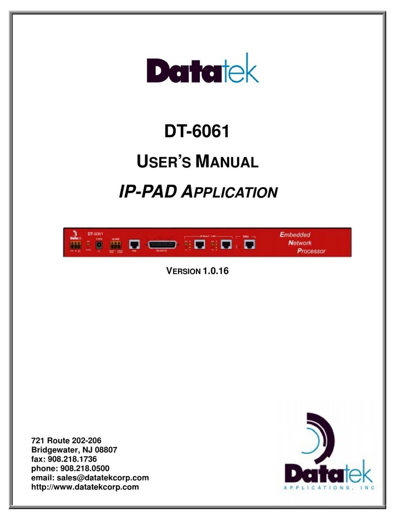
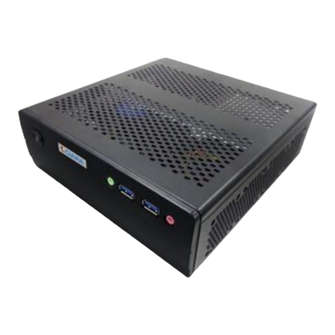
Datatek DT-6061 User manual

IP-SPOOL
APPLICATION
USER'S MANUAL
FOR
DT-6XXX
EMBEDDED NETWORK PROCESSORS
RELEASE.VERSION 12.0
ISSUE 2
379 Campus Drive, Suite 100
Somerset, NJ 08873
fax: 732 667-1091
phone: 732 667-1080
email: sales@datatekcorp.com
http://www.datatekcorp.com

DT-6XXX IP-SPOOL Application User’s Manual – Build 12.0
04/13/06
Datatek Applications Inc. 2
TABLE OF CONTENTS
IMPORTANT SAFETY INSTRUCTIONS.................................................................4
1INTRODUCTION................................................................................................5
2GLOSSARY.......................................................................................................6
3SUGGESTED REFERENCES ...........................................................................7
4DEDICATED PRINTER DEPLOYMENTS .........................................................8
5A SOLUTION...................................................................................................10
6REDUNDANCY & RELIABILITY.....................................................................11
7IP-SPOOL INTERFACES................................................................................12
7.1 Configuring the IP-SPOOL Application...........................................................................12
7.2 Operation............................................................................................................................13
8IP-SPOOL APPLICATION COMMAND SET...................................................14
8.1 Login...................................................................................................................................14
8.2 Logout.................................................................................................................................15
8.3 Change Password - chgpass............................................................................................15
8.4 Help.....................................................................................................................................15
8.5 Banner Message - banner.................................................................................................15
8.6 Application Comments - comment ..................................................................................16
8.7 Label....................................................................................................................................16
8.8 OA&M Session Timer Configuration - timeout...............................................................16
8.9 Version – ver | version ......................................................................................................17
8.10 Defining the Shared Printer - prt ..................................................................................17
8.11 Verify Configured Options – verify | vfy ......................................................................18
8.12 Restoring the Printer Connection – rs | restore..........................................................18
8.13 Removing the Printer Connection – rm | remove .......................................................18
8.14 Displaying Current Connections – dc | dconn............................................................18
8.15 Display Jobs in Queue – dq | dqueue ..........................................................................19
8.16 Purge Jobs in Queue - purge........................................................................................19
8.17 Display Log - dlog..........................................................................................................19
8.18 Display of Measurements - dmeas...............................................................................19
8.19 Clear Measurements – clr | clear..................................................................................19
9IP-SPOOL MEASUREMENTS.........................................................................20
10 APPENDIX A:IP-SPOOL INSTANCE NUMBER TO TCP PORT
CONVERSION TABLE..........................................................................................21
11 Hardware Warranty .....................................................................................22
12 End-User License Agreement for Software ..............................................22
12.1 Software License............................................................................................................22
12.2 Intellectual Property Rights ..........................................................................................22

DT-6XXX IP-SPOOL Application User’s Manual – Build 12.0
04/13/06
Datatek Applications Inc. 3
12.3 Software Support ...........................................................................................................22
12.4 Export Restrictions........................................................................................................22
12.5 Limited Warranty............................................................................................................23
12.6 No Other Warranties......................................................................................................23
12.7 Special Provisions.........................................................................................................23
13 Limitation of Liability..................................................................................23

DT-6XXX IP-SPOOL Application User’s Manual – Build 12.0
04/13/06
Datatek Applications Inc. 4
IMPORTANT SAFETY INSTRUCTIONS
The exclamation point within an equilateral triangle is intended to alert the user to the presence of
important operating and maintenance (servicing) instructions in the literature accompanying the DT-
6XXX product.
When installing, operating, or maintaining this equipment, basic safety precautions should always be followed to reduce the
risk of fire, electric shock, and injury to persons, including the following:
! Read and understand all instructions.
! Follow all warnings and instructions marked on this product.
! For information on proper mounting instructions, consult the User’s Manual provided with this product.
! The telecommunications interface should not leave the building premises unless connected to telecommunication
devices providing primary and secondary protection.
! This product should only be operated from the type of power source indicated in the User’s Manual.
! This unit is intended to be powered from either –48 V DC or AC voltage sources. See User’s Manual before connecting
to the power source.
! The –48 V DC input terminals are only provided for installations in Restricted Access Areas locations.
! Do not use this product near water, for example, in a wet basement.
! Never touch uninsulated wiring or terminals carrying direct current or leave this wiring exposed. Protect and tape wiring
and terminals to avoid risk of fire, electric shock, and injury to service personnel.
! To reduce the risk of electrical shock, do not disassemble this product. Service should be performed by trained
personnel only. Opening or removing covers and/or circuit boards may expose you to dangerous voltages or other risks.
Incorrect re-assembly can cause electric shock when the unit is subsequently used.
! For a unit intended to be powered from –48 V DC voltage sources, read and understand the following:
• This equipment must be provided with a readily accessible disconnect device as part of the building installation.
• Ensure that there is no exposed wire when the input power cables are connected to the unit.
• Installation must include an independent frame ground drop to building ground. Refer to User’s Manual.
This symbol is marked on the DT-6XXX, adjacent to the ground
(earth) area for the connection of the ground (earth) conductor
! This Equipment is to be Installed Only in Restricted Access Areas on Business and Customer Premises Applications in
Accordance with Articles 110-16, 110-17, and 110-18 of the National Electrical Code, ANSI/NFPA No. 70. Other
Installations Exempt from the Enforcement of the National Electrical Code May Be Engineered According to the
Accepted Practices of the Local Telecommunications Utility.
! For a unit used with an AC Wall Plug-In Unit, read and understand the following:
• Contact Datatek Applications, Inc or its authorized resellers for specifications for procuring an AC power unit.
• Unplug this product from the wall outlet before cleaning. Do not use liquid cleaners or aerosol cleaners. Use a
damp cloth for cleaning.
• Do not staple or otherwise attach the power supply cord to the building surfaces.
• Do not overload wall outlets and extension cords as this can result in the risk of fire or electric shock.
• The socket outlet shall be installed near the equipment and shall be readily accessible.
• The Wall Plug-In unit may be equipped with a three-wire grounding type plug, a plug having a third (grounding) pin.
This plug is intended to fit only into a grounding type power outlet. Do not defeat the safety purpose of the
grounding type plug.
• Do not allow anything to rest on the power cord. Do not locate this product where the cord may be abused by
persons walking on it.
• Unplug this product from the wall outlet and refer servicing to qualified service personnel under the following
conditions:
a) When the powers supply cord or plug is damaged or frayed.
b) If liquid has been spilled into the product.
c) If the product has been exposed to rain or water.
d) If the product does not operate normally by following the operating instructions. Adjust only those controls
that are covered by the operating instructions because improper adjustment of other controls may result in
damage and will often require extensive work by qualified technician to restore the product to normal
operation.
e) If the product has been dropped or the cabinet has been damaged.
f) If the product exhibits a distinct change in performance.
Save These Instructions
!

DT-6XXX IP-SPOOL Application User’s Manual – Build 12.0
04/13/06
Datatek Applications Inc. 5
1 INTRODUCTION
Many existing networking equipment consoles have the need for a dedicated print device.
Similarly, legacy hosts and their applications typically assume a dedicated printer of which
their use is exclusive. Many of these print devices are under-utilized, yet require
considerable periodic maintenance. Finally, the physical location of these printers may not
be convenient, due to requirements implied by their legacy interfaces.
Many modern host applications use RFC1179 print spooling to share a common print
resource. The purpose of the IP-SPOOL application is to provide that same functionality to
the dedicated printer interfaces of legacy systems.
The IP-SPOOL application has two distinct purposes.
! Allow convenience by providing the ability to route print output to a shared printer
anywhere in the network infrastructure.
! Reduce the overall cost associated with legacy interfaces by eliminating dedicated
equipment.
By allowing the sharing of otherwise dedicated equipment, the IP-SPOOL application
reduces ongoing costs associated with legacy applications, while providing all of the
functionality expected today.

DT-6XXX IP-SPOOL Application User’s Manual – Build 12.0
04/13/06
Datatek Applications Inc. 6
2 GLOSSARY
BHIM Bisync Host Interface Module – a BNS SYNC* module in cluster controller
emulation mode
BNS
Mnemonic which has no translation and is used to refer to the BNS-2000 family
of products which include BNS-2000 and BNS-2000 VCS (a.k.a. DatakitII
VCS)
CO Central Office
CODEC Coder/Decoder
COLO Central Office Co-Location
DCTU Directly Connected Test Unit
DK Datakit
IP Internet Protocol
LMOS Loop Maintenance Operations System
MLT Mechanized Loop Test Operations System
NE Network Element
OS Operations System
OSS Operations Support System
RFC Request For Comments (Internet Specifications)
SAM BNS Synchronous/Asynchronous Multiplexer
SNMP Simple Network Management Protocol
Datakit is a registered trademark of Lucent Technologies, Inc, licensed to Datatek Applications, Inc., a
company separate from Lucent Technologies, Inc.

DT-6XXX IP-SPOOL Application User’s Manual – Build 12.0
04/13/06
Datatek Applications Inc. 7
TCP Transport Control Protocol
TCP/IP Transport Control Protocol over the Internet Protocol
UMI Universal Mediation Interface (Datakit/BNS interface module)
URP Universal Receiver Protocol
3 SUGGESTED REFERENCES
The following documents are resident at http://www.datatekcorp.com under the support
button.
Document Scope
DT-6061 Embedded Network Processor
User’s Manual (Platform)
Describes the DT-6061 Embedded
Network Processor infrastructure and
command set. This includes configuration
information, hardware specifications, and
SNMP MIB support.
DT-6X60 Embedded Network Processor
Platform User’s Manual
Describes the DT-6160 and DT-6260
Embedded Network Processors’
infrastructure and command set. This
includes configuration information,
hardware specifications, and SNMP MIB
support.
Universal Mediation Interface (UMI)
Module User’s Manual Describes the Universal Mediation
Interface Operations and Administration.
DT-4000 Multiple Protocol Inter-
Networking Device User’s Manual Describes the DT-4000 multi-protocol
terminal server.
DT-9480 - DT-4180 – DT-4280 – DT-4284
- DT-4281 Multiple Protocol Integrated
Access Device User’s Manual
Describes the DT-xx8x multi-protocol
terminal servers.

DT-6XXX IP-SPOOL Application User’s Manual – Build 12.0
04/13/06
Datatek Applications Inc. 8
4 DEDICATED PRINTER DEPLOYMENTS
There are many examples of dedicated printer deployments. Consider the following
diagram:
BiSync Host
BNS VCS
Node B
H
I
M
U
M
I
DT-6061
T
R
K
ASCII Printers
DT-4000
PCs with 3270 Client
Application
IP
Network
TN3270 Application
IP-B2APRT Application
NE NE
DT-4000 ASCII Printer
Interfaces
10BaseT
10BaseT

DT-6XXX IP-SPOOL Application User’s Manual – Build 12.0
04/13/06
Datatek Applications Inc. 9
In the preceding diagram, the PC-based 3270 clients are accessing the host via the TN-
3270 application of the DT-60611. To allow them to issue print requests, the cluster printer
is being emulated by the IP-B2APRT application of the DT-6061 driving a dedicated ASCII
printer. The printer itself is deployed as a BNS endpoint on a DT-4000. The connection
between the IP-B2APRT application and the printer is permanent.
The NE devices generate output for remote ASCII printers (one dedicated to each device).
A DT-4000 is used to provide IP-network access to the NE printer interfaces, while another
DT-4000 connects the printers to the BNS network. The connections between the two DT-
4000s traverse the UMI for mediation between the BNS and IP networks.
While these two printing applications are independent of each other, they have one
significant characteristic in common. The connection to each print device is dedicated. This
maintains the legacy interface, but precludes sharing a print device by multiple users.
1Throughout this document, the reference is to the DT-6160 and DT-4000. For the DT-6160, the DT-6160
and DT-6260 can be used interchangeable. The IP-SPOOL and other applications will run on all three
platforms. The DT-6160 and DT-6260 are the next generation of the DT-6061. They have faster processors
and more memory. The DT-6160 supports up to 30 instances of up to 5 different applications, and the DT-
6260 supports 48 instances. The family of DT-6… processors will be referred to generically as DT-6XXX.
With respect to the DT-4000 in this document, the DT-9480, DT-4180, DT-4280, and DT-4284 can be used in
addition to the DT-4000. The whole family will be referred to as the DT-4XXX. For the purposes of this
document, the differences between the various members of the DT-4XXX family are the number of ports each
has.

DT-6XXX IP-SPOOL Application User’s Manual – Build 12.0
04/13/06
Datatek Applications Inc. 10
5 A SOLUTION
The IP-SPOOL application is transparent to the legacy devices. This allows interoperability
with all existing applications as well as SAM or DT-4XXX connected devices. The IP-
SPOOL application spools (buffers) the print output, and initiates connections to an RFC
1179 capable printer, which can now be shared with other hosts. This is represented in the
following diagram:
In the preceding diagram, each of the NE devices now has a connection to a “virtual
printer”, which is actually an instance of the IP-SPOOL application on the DT-6061. When
TN3270 Application
IP-B2APRT Application
IP-SPOOL Application BiSync Host
BNS VCS
Node
B
H
I
M
U
M
I
DT-6061
RFC1179 Printer
PCs with 3270 Client
Application
IP
Network
NE NE
DT-4000 ASCII Printer
Interfaces
10BaseT
10BaseT

DT-6XXX IP-SPOOL Application User’s Manual – Build 12.0
04/13/06
Datatek Applications Inc. 11
a NE sends data out over its ASCII printer interface, the data is first spooled by the IP-
SPOOL application for a user-defined capture interval. The spooled data is then forwarded
to the shared printer. Similarly, to allow the 3270 clients to continue to print via the IP-
B2APRT application, the latter now has a connection to its own virtual printer – a different
IP-SPOOL instance. This IP-SPOOL application instance forwards data to the same
shared printer.
6 REDUNDANCY & RELIABILITY
The IP-SPOOL application takes advantage of the DT-6XXX redundancy infrastructure (an
optional 1+1 spare arrangement) to enhance its reliability. Should a DT-6XXX fail, the
spare immediately takes over automatically, and assumes the public IP address of the set.
It should be noted that applications do not need to change, or even be made aware of
whether the DT-6XXX is operating in duplex or simplex mode. Refer to the DT-6061
Platform User’s Manual for more information.

DT-6XXX IP-SPOOL Application User’s Manual – Build 12.0
04/13/06
Datatek Applications Inc. 12
7 IP-SPOOL INTERFACES
The TCP port numbers associated with a DT-6XXX application are generally determined
by the instance of the application. There are three distinct interfaces to the IP-SPOOL
application. The TCP port numbers associated with these interfaces are as follows:
Set #Channels TCP Port# Usage
OA&M 1 10000 + instance# Configuration and administration of the
IP-SPOOL application. Connections to
this TCP port are made via a Telnet
client.
Virtual
Printer
1 30000 +
(instance# - 1) * 200
“Virtual Printer” connection is made to
this TCP port.
RFC
1179
Shared
Printer
1 Allocated
Dynamically
The IP-SPOOL application will initiate a
connection to the shared printer when it
has data to print. The TCP port used for
this connection is allocated dynamically
by the DT-6XXX.
7.1 CONFIGURING THE IP-SPOOL APPLICATION
The IP-SPOOL application is first assigned to an instance using the app command on the
DT-6XXX system console. The DT-6XXX infrastructure then starts the IP-SPOOL

DT-6XXX IP-SPOOL Application User’s Manual – Build 12.0
04/13/06
Datatek Applications Inc. 13
application on the specified instance#, which may be in the range of 1 through 302,
inclusive.
After the IP-SPOOL application is operating, the administrator configures the IP-SPOOL
application by connecting to the administrative interface for this particular IP-SPOOL
instance. The TCP port number would be at 10,000 + the instance#. Configuration of the
IP-SPOOL application involves entering the shared RFC1179 printer’s IP address and the
capture timeout period.
7.2 OPERATION
The IP-SPOOL application listens for a call to its “virtual printer” TCP port. A device that
previously had a connection to a dedicated printer may then make a connection to that
TCP port. This connection is permanent.3
When data arrives on the “virtual printer” connection, it will be forwarded to the shared
printer via the RFC1179 protocol (assuming the shared printer IP address is defined). This
is done after the configured capture timeout period has elapsed, or when a high-water
mark in the spooling buffer has been reached.
After the shared printer acknowledges receiving all data sent to it, or a user-configurable
timeout window has elapsed, the connection to the shared printer is disconnected. The
timeout prevents a “hung” connection in the case where the acknowledgement from the
printer was not received, thus allowing other IP-SPOOL instances, as well as any other
host, to attach to the shared printer.
2For the DT-6260, the range is 1 to 48.
3Referring back to the example network shown earlier in this document, each DT-4XXX port to which an NE
printer interface is connected would have its PDD redirected to an instance of the IP-SPOOL application (DT-
6XXX IP address + “virtual printer” TCP port). Similarly, the IP-B2APRT application would be re-
configured to redirect its output to a “virtual printer” instead of a physical printer.

DT-6XXX IP-SPOOL Application User’s Manual – Build 12.0
04/13/06
Datatek Applications Inc. 14
8 IP-SPOOL APPLICATION COMMAND SET
The following conventions are used for commands:
• All parameters may be given on the command line. Parameters of the form
name=<value> may be given in any order.
• Commands may be entered in upper or lower case.
• Parameters of the form name=value may use upper or lower case for name.
• Default values, if any, are shown in parenthesis as part of the prompt.
• Case is not preserved for values.
• Backspace erases one character.
8.1 LOGIN
Syntax: login passwd=<password>
or
Prompted Mode:
Syntax: login
Passwd:
The login command is used to allow access to the other commands. The legal characters
for passwords are the upper and lower case letters, numbers, and the following special
characters:
~ ! @ # $ % ^ & * ( ) _ + { } | : < > ? ` - = [ ] \ ; ‘ , . /
Note that when inputting a password, all of these special characters are allowed. Double
quote is not allowed, nor is equal sign ‘=”allowed as the first character of a password in
prompted mode. Passwords are case sensitive.
The passwd parameter is not echo suppressed. However, if the passwd parameter is not
provided in the command line, the console prompts for a password (i.e. prompted mode);
the response is echo-suppressed in this case.
If the password is valid, the user is placed in the logged in mode. Once the console user is
logged in, the rest of the commands are accessible. The login command is not accessible
if the user is already logged in.

DT-6XXX IP-SPOOL Application User’s Manual – Build 12.0
04/13/06
Datatek Applications Inc. 15
8.2 LOGOUT
Syntax: logout
The logout command is only allowed if the console user is logged in. It uses no
arguments. It will set the console to the logged out mode.
8.3 CHANGE PASSWORD - CHGPASS
Syntax: chgpass PASSWD=<old> NEWPASS=<new> CONFIRM=<new>
The chgpass command is used to change a user password on the system console. The
command is only allowed if the user is logged in.
All three parameters must be given on the same command line. None of those entries are
echo-suppressed.
If the current password is valid and the two entries for the new password match, the
password is changed to the new value.
8.4 HELP
Syntax: help | ? [Command]
The help command is always visible. The help command displays the currently allowed
commands for the mode that the unit is currently entered. An alternative to the help
command is a question mark.
8.5 BANNER MESSAGE - BANNER
Syntax: banner [ L<#>=”System Banner Line <#>” | default ]
The banner command is only visible when the application is logged in. The command is
used to configure a system message banner that is displayed to the administrators upon
connection to the ip-spool application. The banner can consist of a maximum of eight (8)
lines of 60 characters each of text including spaces. Each line may be configured
independently of each other with its own tag (i.e. L1, L2, …, L8). The banner lines are
visible on a verify / vfy command or by invoking the banner command with no

DT-6XXX IP-SPOOL Application User’s Manual – Build 12.0
04/13/06
Datatek Applications Inc. 16
parameters. The use of this command is not required if no banner is desired. The banner
may be cleared by using the banner command using the parameter named default. This
will delete all banner lines.
8.6 APPLICATION COMMENTS - COMMENT
Syntax: comment [ L1=”comment”]
[ L2=”comment”]
[ L3=”comment”]
The comment command allows a user to add user information to the application instance.
The information is displayed during a verify command. Up to three lines of information
may be provided. Each line may be up to 64 characters in length, may include spaces, and
is double quoted. Each line may be changed individually. Comments may be cleared by
setting the line value to a null comment (i.e. “”).
8.7 LABEL
Syntax: label [<“label string”> | none]
If the command is issued without arguments, the current configuration is displayed. When
issued with an argument of none, the label becomes a NULL label. Otherwise, a label up
to 32 characters is allowed when enclosed in double quotes. (The double quotes are not
counted as part of the 32 characters). The label may be a mixture of alpha characters and
digits.
8.8 OA&M SESSION TIMER CONFIGURATION - TIMEOUT
Syntax: timeout [ OFF | <Number of Seconds> ]
The timeout command configures the session timer. Its range is 15 to 254 seconds. When
configured, the session timer will disconnect a user from the OA&M telnet port for this IP-
SPOOL instance. No other instances on the DT-6XXX are affected since each has its own
OA&M connection.

DT-6XXX IP-SPOOL Application User’s Manual – Build 12.0
04/13/06
Datatek Applications Inc. 17
8.9 VERSION – VER | VERSION
Syntax: ver | version
The version command is only visible when the application is logged in. The command has
no arguments. It displays the current software and database revisions of the application.
8.10 DEFINING THE SHARED PRINTER - PRT
Syntax: prt [ dest=<IP-Addr> ] [ timeout=<#secs> ] [ retry=<#secs> ]
[ tcpport=<source TCP port > ] [ queue=<queue name > ]
[ class=<string > ] [ host=<string > ] [ user=<string > ]
[capture=<#secs> ] [errors=<#errors | off>]
The prt command is only visible when the application is logged in. The command is used
to define parameters associated with the shared printer.
The dest parameter defines the IP address of the printer in the format d.d.d.d where d = 0
to 255 decimal. There is no need to specify a TCP port number, since that is specified in
RFC 1179.
The timeout parameter allows the configuration of a hold period of the shared printer after
all buffered data has been sent, as discussed in sec. 7.2.
The retry parameter is the number of seconds to wait before attempting a new connection
to the shared printer when an attempt fails. The range for both timeout and retry is 15-255
seconds.
The tcpport parameter is the originating TCP port to be used for the connection to the
shared printer. RFC 1179 requires the TCP port to be between 721 and 731, inclusive.
However, many printers do not require this. If the port is defined as zero (the default value)
the next available port will be used.
The queue parameter is the name of the printer. The value <queue name> is a single
word with a maximum of 32 characters.
The class, host and user strings correspond to the ‘C’, ‘H’ and ‘P’ commands used in the
control file as defined in RFC 1179. This allows customization the fields that will be used

DT-6XXX IP-SPOOL Application User’s Manual – Build 12.0
04/13/06
Datatek Applications Inc. 18
on the control page for the individual device. Each string is a single word with no quotes
and can be up to 30 characters long.
The capture parameter is used to define the time period between the initial arrival of data
on the virtual printer interface and the time a connection is made to the shared printer. Use
of the capture period minimizes “thrashing” for devices that have irregular printing patterns.
This allows customization for the individual device. The range for the capture timeout is 15
to 255 seconds.
The errors parameter is the number of consecutive errors required before the application
will remove the printer from service. The "off" option will disable the auto remove printer
function. The range of errors is 1 to 10.
8.11 VERIFY CONFIGURED OPTIONS – VERIFY | VFY
Syntax: verify | vfy
The verify (vfy) command is only visible when the application is logged in. The command
is used to display the configured options.
8.12 RESTORING THE PRINTER CONNECTION – RS | RESTORE
Syntax: rs | restore prt
The rs prt command is only visible when the application is logged in. It puts the printer
connection "in service". The printer connection must be "in service" before a connection to
a RFC1179 printer will be attempted.
8.13 REMOVING THE PRINTER CONNECTION – RM | REMOVE
Syntax: rm | remove prt
The rm prt command is only visible when the application is logged in. It takes the printer
connection "out of service". Any existing connections will be taken down and no new
connections will be established even if there is data to print.
8.14 DISPLAYING CURRENT CONNECTIONS – DC | DCONN
Syntax: dc | dconn

DT-6XXX IP-SPOOL Application User’s Manual – Build 12.0
04/13/06
Datatek Applications Inc. 19
The dconn (dc) command is used to display all of the current connections into the IP-
SPOOL application. The command does not require any arguments. The report shows the
connection peer for each active connection.
8.15 DISPLAY JOBS IN QUEUE – DQ | DQUEUE
Syntax: dq | dqueue
The dq command displays all jobs in the queue assigned to the application instance.
8.16 PURGE JOBS IN QUEUE - PURGE
Syntax: purge [ queue=<queue name>] [ confirm=yes]
The purge command deletes all jobs currently in the queue, where <queue name> is the
configured queue name for this instance of the application. The queue and confirm
arguments are both required as shown, since the command is destructive and irreversible.
8.17 DISPLAY LOG - DLOG
Syntax: dlog | dlog clr
The dlog command is only visible when the application is logged in. This command is
used to display the entries in the error log. An exclamation point ( ! ) that precedes a log
entry denotes new entries. A double asterisk ( ** ) that precedes a log entry denotes
folding of multiple similar entries into a single line. The log file can be cleared with the
command: dlog clr
8.18 DISPLAY OF MEASUREMENTS - DMEAS
Syntax: dmeas
The dmeas command is only visible when the application is logged in. The command is
used to display the current measurements on all of the interfaces.
8.19 CLEAR MEASUREMENTS – CLR | CLEAR
Syntax: clr | clear
The measurements displayed with the dmeas command are aggregated until cleared. The
clr command will set all measurements to zero. The command has no arguments.

DT-6XXX IP-SPOOL Application User’s Manual – Build 12.0
04/13/06
Datatek Applications Inc. 20
9 IP-SPOOL MEASUREMENTS
This section itemizes the measurements available using the display measurements
(dmeas) command.
The base measurements are always displayed, and the error and exception counters are
only displayed if nonzero.
The measurements available are as follows:
Measurement Description Type
Number of characters Received on the virtual printer interface Base
Number of characters Sent on the virtual printer interface Base
Number of characters Received on the Shared Printer interface Base
Number of characters Sent on the Shared Printer interface Base
Number of successful connections to the Shared Printer. Base
Number of connection attempts to the Shared Printer Exception
Other manuals for DT-6061
1
This manual suits for next models
2
Table of contents
Other Datatek Computer Hardware manuals
Popular Computer Hardware manuals by other brands
FRONIUS
FRONIUS SolarCity Card operating instructions
i-See
i-See IGEP COM AQUILA AM335x Hardware reference manual
Multitech
Multitech QuickCarrier MT100UCC Series Developer's guide
Promise
Promise Pegasus R4 installation guide
SIGMA TEK
SIGMA TEK S-DIAS AI 084 instruction manual

Ebmpapst
Ebmpapst 3218 JH operating instructions
