DATEC 1630.04140/70100 User manual
Technical Manual
KNX/DALI ACTUATOR
1x8 channels
Art. 1630.04140/70100
Because of continuous product improvement, notice
is subject to change without notification.
Please always check for latest version. Refer to
www.datec.ch or contact [email protected]
DATEC ELECTRONIC AG
Hochbergerstrasse 60C
4057 Basel
Tel. +41 61 633 22 25, Fax. +41 61 633 22 27
www.datec.ch, [email protected]
Technical Manual
KNX/DALI ACTUATOR - Art. 1630.04140/70100
DATEC ELECTRONIC AG –Hochbergerstrasse 60C, 4057 Basel
TEL. + 41 61 633 22 25 –FAX. + 41 61 633 22 27 –[email protected] - www.datec.ch.ch v26/14E Page | 2
1.1. Presentation....................................................................................................................................................................................................3
1.2. Overall view...................................................................................................................................................................................................4
1.3. Connection diagram .......................................................................................................................................................................................5
2. Operating manual ..................................................................................................................................................................................................6
2.1. Inputs / Outputs..............................................................................................................................................................................................6
2.1.1 KNX (input / output)................................................................................................................................................................................6
2.1.2 DALI (input / output)...............................................................................................................................................................................6
2.2. Local push-buttons and LED’s.......................................................................................................................................................................7
2.2.1 KNX Programming button “Prog.” and LED ..........................................................................................................................................7
2.2.2 DALI Learning button “Learn.” and LED ...............................................................................................................................................7
2.2.3 Channel A- D, Channel E- H buttons and LED’s ....................................................................................................................................8
2.3 DALI addressing.............................................................................................................................................................................................9
2.3.1 Start addressing........................................................................................................................................................................................9
2.3.2 Physical addressing................................................................................................................................................................................10
2.3.3 Random addressing................................................................................................................................................................................10
2.3.4 Exiting addressing..................................................................................................................................................................................10
3. Application description........................................................................................................................................................................................12
3.1. Communication objects................................................................................................................................................................................12
3.1.1 Device operating status..........................................................................................................................................................................12
3.1.2 DALI power switch On-Off / DALI power status ...................................................................................................................................12
3.1.3 Buzzer switch On–Off / Buzzer status ....................................................................................................................................................13
3.1.4 DALI send single....................................................................................................................................................................................14
3.1.5 DALI send twice.....................................................................................................................................................................................15
3.1.6 DALI query ............................................................................................................................................................................................16
3.1.7 DALI answer value ................................................................................................................................................................................17
3.1.8 DALI got answer....................................................................................................................................................................................17
3.1.9 DALI answer error.................................................................................................................................................................................18
3.1.10 DALI overload status...........................................................................................................................................................................18
3.1.11 Physical addressing / Addressing status..............................................................................................................................................19
3.1.12 Random addressing..............................................................................................................................................................................20
3.1.13 Erase short address..............................................................................................................................................................................21
3.1.14 Central switch On-Off..........................................................................................................................................................................22
3.1.15 Central dimm relative..........................................................................................................................................................................22
3.1.16 Central dimm absolute.........................................................................................................................................................................23
3.1.17 Central mode switch On-Off / Central mode status .............................................................................................................................23
3.1.18 Scene control .......................................................................................................................................................................................24
3.1.19 Channel A switch On-Off.....................................................................................................................................................................25
3.1.20 Channel A On-Off status......................................................................................................................................................................25
3.1.21 Channel A dimm relative......................................................................................................................................................................26
3.1.22 Channel A dimm absolute....................................................................................................................................................................26
3.1.23 Channel A brightness status.................................................................................................................................................................27
3.1.24 Channel A Slave mode switch On-Off / Channel A Slave mode status.................................................................................................27
3.1.25 Channel A (re)start Burn in / Channel A Burn in status......................................................................................................................28
3.1.26 Channel A burning time status.............................................................................................................................................................28
3.1.27 Channel A relamping time elapsed status............................................................................................................................................29
3.1.28 Channel A restart burning time............................................................................................................................................................29
3.1.29 Channel A (re)start Stairlight ..............................................................................................................................................................30
3.1.30 Channel A Force On-Off / Channel A Force status .............................................................................................................................30
3.1.31 Channel A ballast failure status...........................................................................................................................................................31
3.1.32 Channel A ballast missing status .........................................................................................................................................................32
3.1.33 Channel A lamp failure status..............................................................................................................................................................32
3.2 Parameter description....................................................................................................................................................................................33
3.2.1 General parameters ................................................................................................................................................................................33
3.2.2 Buzzer parameters..................................................................................................................................................................................33
3.2.3 Channels parameters..............................................................................................................................................................................34
3.2.4 Channel A parameters............................................................................................................................................................................36
3.2.5 Stairlight channel A parameters.............................................................................................................................................................39
3.2.6 Central control parameters.....................................................................................................................................................................42
3.2.7 Scenes 1…32 parameters.......................................................................................................................................................................44
3.2.8 Scene 1 parameters ................................................................................................................................................................................45
3.2.9 General sending parameters...................................................................................................................................................................47
4. Technical data: Art. 1630.04140/70100...............................................................................................................................................................48
Technical Manual
KNX/DALI ACTUATOR - Art. 1630.04140/70100
DATEC ELECTRONIC AG –Hochbergerstrasse 60C, 4057 Basel
TEL. + 41 61 633 22 25 –FAX. + 41 61 633 22 27 –[email protected] - www.datec.ch.ch v26/14E Page | 3
1. Overview
1.1. Presentation
The Datec KNX/DALI Actuator 1x 8 channels is a device for controlling and monitoring up to 8 independent DALI ballast.
With its KNX input which is transformed into a DALI signal it is not necessary to have complex electrical installations, and thanks
to its decentralized housing it can be installed near the lighting equipment (suspend ceilings) to avoid additional wiring costs.
Each lamp may also be controlled manually using the buttons on front of device. Some parts of the monitoring are directly
visible on the device itself. This is useful for lamp commissioning and testing the installation, even without KNX Programming.
KNX bus Power is sufficient for this purpose.
The KNX / DALI Actuator is able to drive 8 independent DALI channels
Description:
-Each ballast can be set up, controlled and monitored independently.
-Handmode is available for the individual addressing of each single ballast and to test each single lamp.
-The DALI power supply is included in the KNX / DALI actuator, powered only by the KNX bus: No need of external
DALI power supply, no need of powering KNX/DALI Actuator with supplementary supply voltage
-LEDs for status indication of each single lamp signals communication failure, ballast failure or lamp failure
-1 KNX input / 1 DALI line output.
To configure and operate the KNX / DALI Actuator, at least ETS version 4 is needed.
The product database is available for download: http://www.datec.ch/1630.03140-70100.html
In case of internal failure of a DALI Ballast high voltage may be present on DALI connector. Thus, device is to
be installed by skilled personal only!
Technical Manual
KNX/DALI ACTUATOR - Art. 1630.04140/70100
DATEC ELECTRONIC AG –Hochbergerstrasse 60C, 4057 Basel
TEL. + 41 61 633 22 25 –FAX. + 41 61 633 22 27 –[email protected] - www.datec.ch.ch v26/14E Page | 4
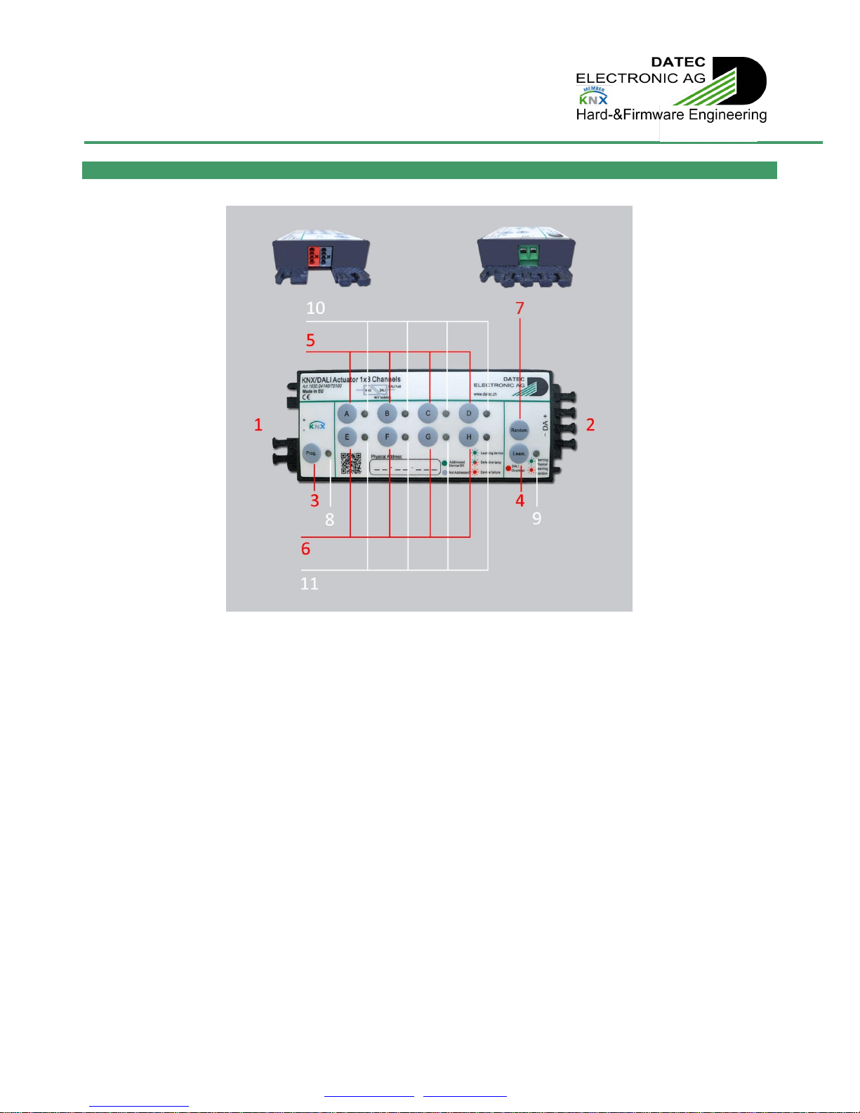
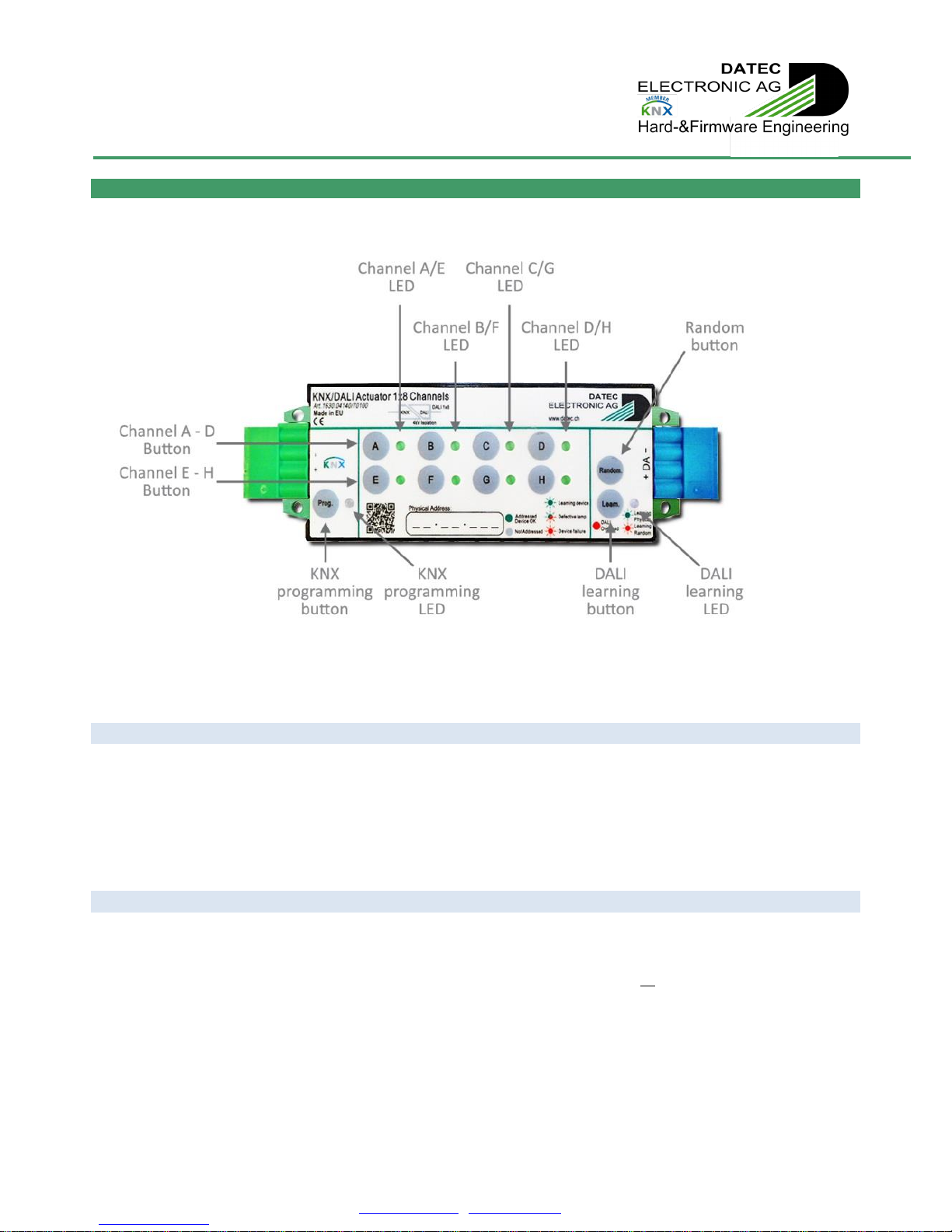
1.2. Overall view
Terminals:
Buttons:
LED’s:
1. KNX plug in connector
3. KNX programming button
8. KNX programming LED
2. DALI screw terminal
4. DALI learning button
9. DALI learning/random/overload LED
5. Channel A to D button
6. Channel E to H button
10. Channel A to D LED
11. Channel E to H LED
7. Random button
Technical Manual
KNX/DALI ACTUATOR - Art. 1630.04140/70100
DATEC ELECTRONIC AG –Hochbergerstrasse 60C, 4057 Basel
TEL. + 41 61 633 22 25 –FAX. + 41 61 633 22 27 –[email protected] - www.datec.ch.ch v26/14E Page | 5
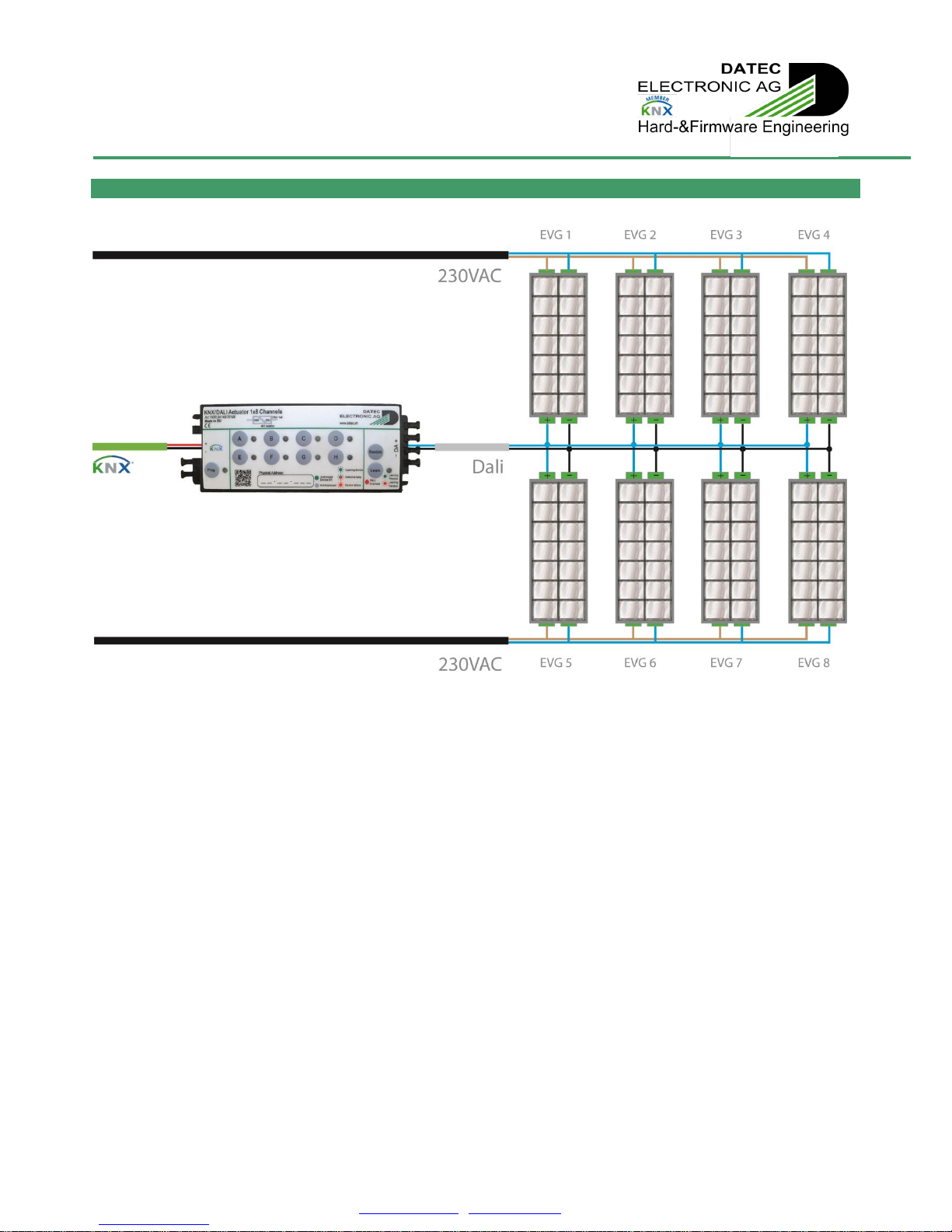
1.3. Connection diagram
Figure 1: Connection diagram
Technical Manual
KNX/DALI ACTUATOR - Art. 1630.04140/70100
DATEC ELECTRONIC AG –Hochbergerstrasse 60C, 4057 Basel
TEL. + 41 61 633 22 25 –FAX. + 41 61 633 22 27 –[email protected] - www.datec.ch.ch v26/14E Page | 6
2. Operating manual
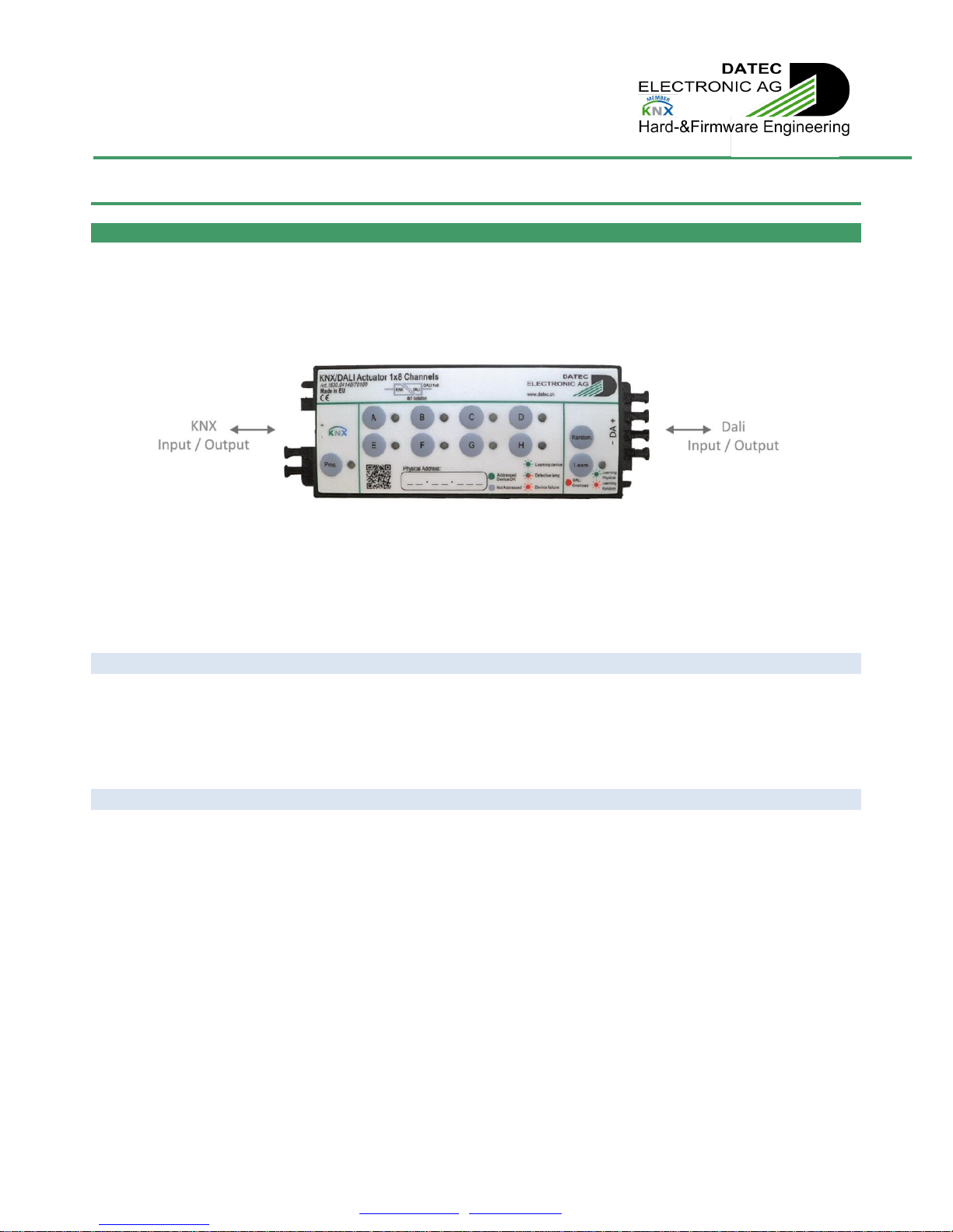
2.1. Inputs / Outputs
Figure 2: Inputs / Outputs
2.1.1 KNX (input / output)
The KNX / DALI actuator is powered from the KNX bus, through a 2-pole plug in connector.
The KNX bus is used for bi-directional communication with other devices. Commands to the lamps are received from KNX, and
status information’s are sent back to KNX bus.
2.1.2 DALI (input / output)
The device is designed to drive up to 8 independent ballasts connected on DALI bus.
The DALI bus is used for bi-directional communication with other devices.
Commands and settings are sent to ballasts through the DALI bus. Statuses from ballasts are received through the DALI bus.
Each single ballast can be set up, controlled and monitored independently.
The DALI bus power supply is included in the KNX / DALI actuator, and is fully powered by the KNX bus.
The internal DALI power supply is able to power up to 8 ballasts, each using max. 2mA, according to DALI standard.
Inside the KNX / DALI actuator, KNX and DALI bus are isolated from each other.
The KNX / DALI actuator acts as a DALI Master. Only 1 Master is allowed in a DALI system.
In no case, another DALI Master or DALI power supply must to be connected to the KNX / DALI actuator.
Technical Manual
KNX/DALI ACTUATOR - Art. 1630.04140/70100
DATEC ELECTRONIC AG –Hochbergerstrasse 60C, 4057 Basel
TEL. + 41 61 633 22 25 –FAX. + 41 61 633 22 27 –[email protected] - www.datec.ch.ch v26/14E Page | 7
2.2. Local push-buttons and LED’s
Figure 3: Local push-buttons and LED’s
2.2.1 KNX Programming button “Prog.” and LED
Pressing the KNX programming button “Prog.” will put the KNX / DALI actuator into KNX Programming mode. The KNX
programming mode will be exited automatically after successful physical address programming, resetting device or pressing
again the “Prog.” button.
The associated LED (KNX Programming LED) is indicating programming mode by red lighting.
2.2.2 DALI Learning button “Learn.” and LED
A short press on the DALI Learning button “Learn.” will enter or exit DALI Learning mode.
Once in manual learning mode, a long press on the DALI Learning button “Learn.” will erase all short addresses on the DALI Bus.
This will not only erase DALI short addresses affected to the channels A…H, but all short addresses from 0 to 63. This is useful if
some ballast already have a short address which is not affected to a channel. In this case, even this address can be erased, in
order to give a new address according to settings of channels A…H.
The associated LED (DALI learning LED) is indicating the actual DALI learning mode:
-Blinking green: device is actually in physical learning mode
-Blinking red: device is actually in random learning mode
-Red (not blinking): there is an overload on the DALI bus, for ex. too much ballasts connected or short circuit.
Technical Manual
KNX/DALI ACTUATOR - Art. 1630.04140/70100
DATEC ELECTRONIC AG –Hochbergerstrasse 60C, 4057 Basel
TEL. + 41 61 633 22 25 –FAX. + 41 61 633 22 27 –[email protected] - www.datec.ch.ch v26/14E Page | 8
2.2.3 Channel A- D, Channel E- H buttons and LED’s
If not in addressing mode, a short press on buttons “A…H” will invert the level of corresponding channel.
-If corresponding channel is off, the ballast will be requested to jump to the maximum level set in parameters
-If corresponding channel is already on, the ballast will be requested to jump to off.
This is useful to check the electrical installation and also the DALI addressing. By this way, electricians can check if the
communication between KNX / DALI actuator is working, and if the ballasts are associated to the correct channels.
By the same way, the actual status of each channel is displayed on the corresponding LED:
-Off: the associated channel is not used
-Constant green: ballast with corresponding short address is responding, no ballast or bulb failure
-Alternate green-red blinking: ballast with corresponding short address is signalling a lamp failure. Lamp has to be
checked. Defective lamps can only be detected when ballast is requested to switch them on.
-Red blinking: no ballast with corresponding short address is responding. Power supply of ballast, addressing of
associated short address and wiring have to be checked
-Constant red: ballast with corresponding short address is signalling an internal failure. Ballast has to be checked
-Alternate red-orange blinking: failure on DALI answer. This may be due to bus disturbance, bus overload, multiple
ballasts having same short address, … Addressing and wiring of ballasts has to be checked.
If in addressing mode, a short press on buttons “A…H” will toggle corresponding channel addressing mode On or Off (if channel
not already addressed).
-If a ballast with corresponding short address is already detected, short press of button “A..H” will have no effect
-If no ballast with corresponding short address is detected, a short press of button “A..H” will invert learning status
of associated channel
-A long press of button “A..H” of already addressed channels will make ballast of corresponding channel jump to
minimum level and erase previous short address.
The addressing status of each channel is displayed on corresponding LED “A..H”
-Off: no ballast with corresponding short address is detected, and channel is not in learning mode
-Green blinking: no ballast with corresponding short address is detected, but channel is in learning mode
-Constant green: a ballast with corresponding short address is already detected, so channel is not in learning mode.

Technical Manual
KNX/DALI ACTUATOR - Art. 1630.04140/70100
DATEC ELECTRONIC AG –Hochbergerstrasse 60C, 4057 Basel
TEL. + 41 61 633 22 25 –FAX. + 41 61 633 22 27 –[email protected] - www.datec.ch.ch v26/14E Page | 9
2.3 DALI addressing
In order to work, each single ballast has to be associated to a single channel of the KNX / DALI actuator.
Each channel must only be associated to 1 ballast, and each ballast must only be associated to 1 channel, else DALI
communication failures will occur.
To do this, each KNX / DALI actuator channel will be given a unique and single short address number within parameters. Through
DALI addressing, each ballast will be programmed a corresponding short address number.
The DALI addressing can be initiated either manually on the KNX / DALI actuator, using the push buttons, or it can be initiated
through KNX, using according communication objects.
The manual DALI addressing on device is very useful for electricians, thus this can be done without previous KNX programming.
Only KNX bus power is needed. In this case, the default short address of 0 is used for channel A, 1 for channel B … and 7 for
channel H.
The DALI addressing through KNX is very useful once the KNX / DALI actuator is mounted, for example in fall-ceiling. In this case,
the DALI addressing can be done without need of manual access to the KNX / DALI actuator.
Furthermore, independently of using the push-buttons or the KNX bus, 2 different addressing methods are possible, using either
physical addressing or random addressing.
2.3.1 Start addressing
DALI addressing can be started either manually by short pressing the DALI learning button on KNX / DALI actuator, or through
KNX, by sending according data’s on CO Nr. 10/ Physical addressing / Addressing status.
Once in addressing mode, DALI learning LED will blink green and all connected ballasts will jump to minimum level, according to
parameters.
All ballast with already affected short address corresponding to a channel of the KNX / DALI actuator will then jump to maximum
level, according to parameters, respecting order A to H.
-LED’s “A..H” of already addressed channels will light up constant green.
-LED’s “A..H” of not addressed channels being in addressing mode will blink green.
-LED’s “A..H” of not addressed channels not being in addressing mode will not light.
-Short pressing buttons “A..H” of not addressed channels will toggle corresponding channel addressing mode On or
Off.
-Long pressing buttons “A..H” of already addressed channels will make ballast of corresponding channel jump to
minimum level and erase previous short address.
-Long pressing DALI Learning button “Learn.” will erase all short addresses on the DALI Bus: This will not only erase
DALI short addresses affected to the channels A…H, but all short addresses from 0 to 63. This is useful if some
ballast already have a short address which is not affected to a channel. In this case, even this address can be
erased, in order to give a new address according to settings of channels A…H.
-Erasing short address of ballast can also be done through KNX using CO Nr. 12/ Erase ballast short address.
Rem.: Erasing short address of ballast using CO Nr. 12/ Erase ballast short address will also result in exiting addressing mode.
Rem.: Information about channels in addressing mode is also constantly available on CO Nr. 10/ Physical addressing / Addressing
status.
Rem.: When entering addressing, all channels are automatically checked for available ballast. For each ballast found, a short
sound will be emitted by buzzer. Also, each time a new ballast is successfully addressed, this short sound will be emitted. Theses
short sounds will not be emitted if buzzer is already switched On by CO Nr. 2/ Buzzer switch On-Off / Buzzer status.

Technical Manual
KNX/DALI ACTUATOR - Art. 1630.04140/70100
DATEC ELECTRONIC AG –Hochbergerstrasse 60C, 4057 Basel
TEL. + 41 61 633 22 25 –FAX. + 41 61 633 22 27 –[email protected] - www.datec.ch.ch v26/14E Page | 10
2.3.2 Physical addressing
Physical addressing enables exact commissioning of the ballast, but requires manual access to the lamps.
Once desired channels are in manual addressing mode, the not actually addressed ballasts (recognizable because they are at
minimum level) have to be selected physically one by one.
For this, please refer to ballast manufacturer. In most case, it simply needs to turn out and in again the tube.
The selected ballast will be given the short address associated to the first channel (starting A, Ending H) in addressing mode. This
channel will then exit addressing mode, and associated ballast switch to maximum level (according to parameters).
Rem.: If selecting an already addressed ballast (recognizable because they are at maximum level), this will lose previous short
address, replaced by new one.
Physical addressing can also be achieved without having to access the lamps after mounting. Ballast can be given short
address even before mounting into the ceiling. This short address will be stored inside ballast even once power supply is
removed. If already addressed ballasts, with short addresses corresponding to channels A..H are connected, the KNX /
DALI actuator will recognize them even without having to enter DALI addressing mode.
2.3.3 Random addressing
Random addressing enables rapid commissioning of the ballast, without needing manual access to the lamps.
In most cases, the random association of ballast and channels is not predictable and has to be corrected / adjusted in a second
step.
Instead of selecting ballasts one by one, randomising can be started by short pressing “Random.”button.
The learning LED on KNX / DALI actuator will blink red.
All connected ballasts will first jump to minimum level, and once addressed, jump one after each other, from A to H, to
maximum level.
Ballasts without short address will be selected using a random procedure.
The selected ballast will be given the short address associated to the first channel (starting A, Ending H) in addressing mode. This
channel will also exit addressing mode, and associated ballast switch to maximum level (according to parameters).
Random procedure will continue until no channels are left in addressing mode or no more ballasts without short addresses are
detected.
Rem.: Random addressing can also be started through KNX, by sending according data’s on CO Nr. 11/ Random addressing.
2.3.4 Exiting addressing
The DALI addressing mode will be exited automatically in different ways, for example:
- After a given time, about 15 minutes after last manual addressing action on push buttons
- If a DALI addressing function started through KNX Bus is accomplished
- When resetting device
- If pressing again shortly the “Learn.” button.
- Within random procedure, once no channels are left in addressing mode or no more ballasts without short addresses
are detected anymore.
Technical Manual
KNX/DALI ACTUATOR - Art. 1630.04140/70100
DATEC ELECTRONIC AG –Hochbergerstrasse 60C, 4057 Basel
TEL. + 41 61 633 22 25 –FAX. + 41 61 633 22 27 –[email protected] - www.datec.ch.ch v26/14E Page | 11
Rem.: Complete addressing procedure is valid for all channels, even if set as “Not used” within parameters.
Rem.: While addressing, parameters are stored in all detected ballast. Parameters are also stored on restart of KNX / DALI
actuator.
Avoid pressing “DALI learning”button while start-up of device: If “DALI learning”button is pressed while
device is starting up, it will execute a master reset, erasing all parameters, physical address and group objects.
Instead starting normally, device will only show a rapid green blinking of the “KNX Programming”LED. Even
re-starting device will not recover erased data’s. Handmode is also disabled. Device has first to be re-
programmed through KNX-Bus before recovering functionality. Also, after master reset, KNX programming
mode will be displayed by orange rapid blinking of the “KNX Programming”LED (instead of standard red
lighting).
Rem.: master reset will have no incidence on data’s already stored within ballasts (short address, minimum or
maximum value, …).

Technical Manual
KNX/DALI ACTUATOR - Art. 1630.04140/70100
DATEC ELECTRONIC AG –Hochbergerstrasse 60C, 4057 Basel
TEL. + 41 61 633 22 25 –FAX. + 41 61 633 22 27 –[email protected] - www.datec.ch.ch v26/14E Page | 12
3. Application description
3.1. Communication objects
In this document are listed different communication objects (CO’s). According to the settings done within the parameters, some
of the CO’s may NOT be visible because not relevant anymore.
Figure 4: Communication object device
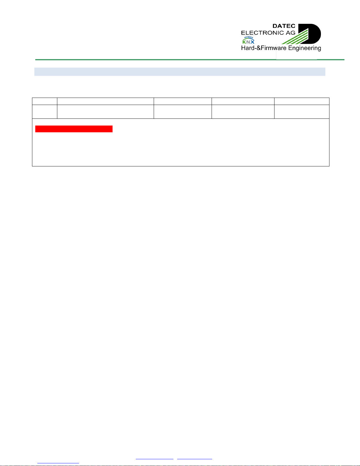
3.1.1 Device operating status
The object 0 monitors the operating status of the KNX / DALI actuator device.
Number
Name
Function
Length
Flags
0
Device operating status
Inactive / Active
1 bit
C/T
1: Device is running
0: -
The KNX / DALI actuator can send “1” for signalling activity. This CO can be used for monitoring the device if set to be sent
cyclically, so failing devices can be detected.
Some special components inside the KNX / DALI actuator are temperature monitored. In case of internal overheating, device will
switch Off DALI bus supply and stop communicating on KNX. So, no CO Nr. 0/ will be sent anymore. After resuming from
overheating, device will restart normal operation and, if selected to do, CO Nr. 0/ can be sent again.
(Red values are default)
3.1.2 DALI power switch On-Off / DALI power status
The object 1 is used to switch On-Off and to monitor the internal DALI power supply of the KNX / DALI actuator device.
Number
Name
Function
Length
Flags
1
DALI power switch On-Off /
DALI power status
Off / On
Inactive / Active
1 bit
C/W/T
1: Switch On DALI power supply / DALI power supply is On
0: Switch Off DALI power supply / DALI power supply is Off
Sending a “0” on CO Nr. 1/ will switch Off the DALI power supply. All connected and learned ballasts will set output level
according to parameter “output level at system failure”.
Sending a “1” on CO Nr. 1/ will switch On the DALI power supply.
Also, the actual DALI power status is available on CO Nr. 1/.
Rem.: On restart of device (after KNX bus power recovery, after programming, …), DALI power is automatically switched On.
Rem.: This CO may also be used to save energy in empty rooms. For this, set System failure level of all channels to Off, and also
switch Off DALI power using CO Nr. 1/ while no presence. So, no energy will be wasted on DALI bus while all lamps are Off, and
this will also reduce KNX bus current. Once presence is detected, switch On DALI power using CO Nr. 1/. Some DALI ballasts may
need a few 100ms before being able to get DALI telegrams.
Rem.: While DALI power supply is Off, all channels will be considered as missing and Off.
Technical Manual
KNX/DALI ACTUATOR - Art. 1630.04140/70100
DATEC ELECTRONIC AG –Hochbergerstrasse 60C, 4057 Basel
TEL. + 41 61 633 22 25 –FAX. + 41 61 633 22 27 –[email protected] - www.datec.ch.ch v26/14E Page | 13
3.1.3 Buzzer switch On–Off / Buzzer status
The object 2 is used to switch On-Off and monitor the internal buzzer of the KNX / DALI actuator device.
Number
Name
Function
Length
Flags
2
Buzzer switch On-Off /
Buzzer status
Off / On
Inactive / Active
1 bit
C/W/T
1: Switch buzzer On / Buzzer is On
0: Switch buzzer Off / Buzzer is Off
Sending a “1” on CO Nr. 2/ will switch On internal buzzer of KNX / DALI actuator for a given time, according to parameters.
Sending a “0” on CO Nr. 2/ will switch Off internal buzzer of KNX / DALI actuator immediately.
Also, the actual buzzer status is available on CO Nr. 2/.
Rem.: On restart of device (after KNX bus power recovery, after programming, …), buzzer is automatically switched Off.

Technical Manual
KNX/DALI ACTUATOR - Art. 1630.04140/70100
DATEC ELECTRONIC AG –Hochbergerstrasse 60C, 4057 Basel
TEL. + 41 61 633 22 25 –FAX. + 41 61 633 22 27 –[email protected] - www.datec.ch.ch v26/14E Page | 14
Figure 5: Communication object DALI
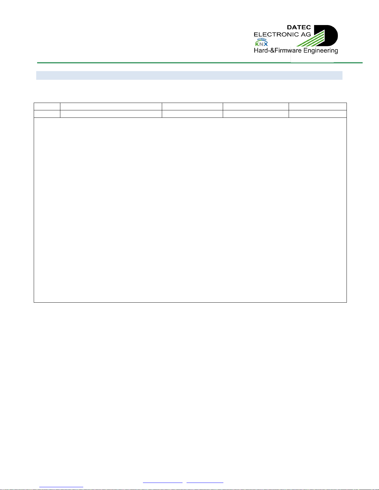
3.1.4 DALI send single
The object 3 is used to send custom specific DALI single forward telegrams through the KNX / DALI actuator device.
Number
Name
Function
Length
Flags
3
DALI send single
DALI command
2 bytes
C/W
1st byte: DALI address, according to DALI standard:
Encoding: YAAA AAAS
64 short addresses, 0..63 0AAA AAAS
16 group addresses, 0..15 100A AAAS
Broadcast 1111 111S
Special commands 1010 000 … 1111 1101
Y = “0”: short address
Y = “1”: group address or broadcast
A = address
S = “0”: databyte = direct arc power
S = “1”: databyte = command
2nd byte: DALI command / direct arc power
Encoding: XXXX XXXX
S = “0”: XXXX XXXX = direct arc power: 0 = 0% … 254 = 100% (not linear !), 255 = mask
S = “1”: databyte = command
CO Nr. 3/ is not a standard KNX datapoint type.
It can be used to send custom specific DALI single forward telegrams on the DALI line, using the KNX / DALI actuator.
Care should be taken, because this may result in undefined behaviour, and shall be reserved to DALI specialists.
The KNX / DALI actuator will transmit the command on DALI line like a standard single forward telegram, according to DALI
standard, respecting DALI frame format and delay between telegrams, but without any control if data’s are valid.
CO Nr. 3 can also be used to switch Off all connected ballasts, even if not addressed. For this, simply send
“$FF $00” (Broadcast jump Off) on CO Nr. 3/. This can be very helpful if needed to switch Off lights on building site as
long as commissioning is not finished.
The same way, all connected ballasts can be switched to maximum level by sending “$FF $05” (broadcast jump to
maximum) on CO Nr. 3/.
For further information, please consult DALI standard, EN 62386-102.
Technical Manual
KNX/DALI ACTUATOR - Art. 1630.04140/70100
DATEC ELECTRONIC AG –Hochbergerstrasse 60C, 4057 Basel
TEL. + 41 61 633 22 25 –FAX. + 41 61 633 22 27 –[email protected] - www.datec.ch.ch v26/14E Page | 15
3.1.5 DALI send twice
The object 4 is used to send custom specific DALI double forward telegrams through the KNX / DALI actuator device.
Number
Name
Function
Length
Flags
4
DALI send twice
DALI command
2 bytes
C/W
1st byte: DALI address, according to DALI standard:
Encoding: YAAA AAAS
64 short addresses, 0..63 0AAA AAAS
16 group addresses, 0..15 100A AAAS
Broadcast 1111 111S
Special commands 1010 000 … 1111 1101
Y = “0”: short address
Y = “1”: group address or broadcast
A = address
S = “0”: databyte = direct arc power
S = “1”: databyte = command
2nd byte: DALI command / direct arc power
Encoding: XXXX XXXX
S = “0”: XXXX XXXX = direct arc power: 0 = 0% … 254 = 100%, 255 = mask
S = “1”: databyte = command
CO Nr. 4/ is not a standard KNX datapoint type.
Some DALI telegrams, used for example for configuration, have to be sent twice with an exact delay of 100ms, without any other
telegram in between. These are called DALI double forward telegrams.
CO Nr. 4/ can be used to send custom specific DALI double forward telegrams on the DALI line, using the KNX / DALI actuator.
Care should be taken, because this may result in undefined behaviour, and shall be reserved to DALI specialists.
The KNX / DALI actuator will transmit twice the command on DALI line like a standard double forward telegram, according to
DALI standard, respecting DALI frame format and delay between telegrams, but without any control if data’s are valid.
For further information, please consult DALI standard, EN 62386-102.
Technical Manual
KNX/DALI ACTUATOR - Art. 1630.04140/70100
DATEC ELECTRONIC AG –Hochbergerstrasse 60C, 4057 Basel
TEL. + 41 61 633 22 25 –FAX. + 41 61 633 22 27 –[email protected] - www.datec.ch.ch v26/14E Page | 16
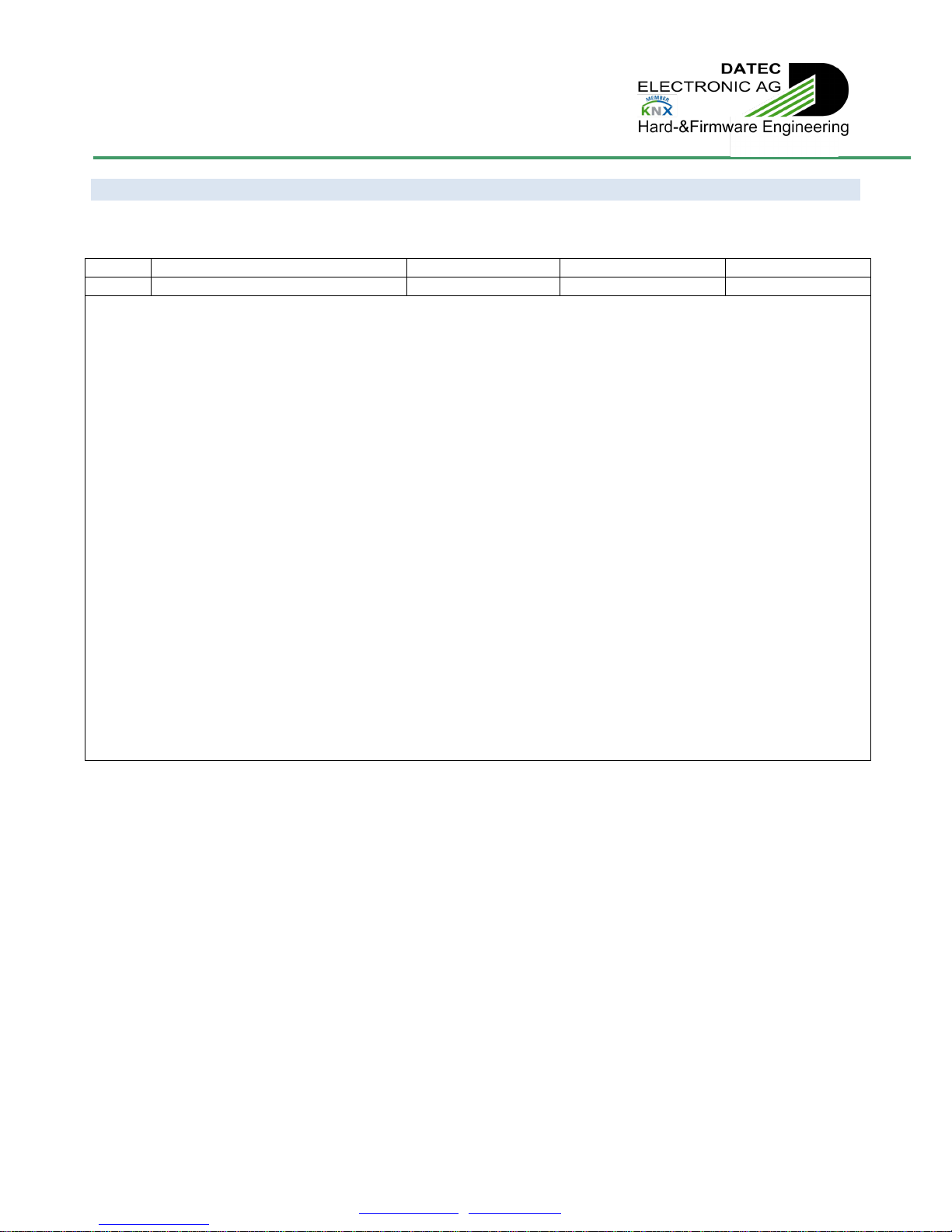
3.1.6 DALI query
The object 5 is used to query custom specific DALI answer telegrams through the KNX / DALI actuator device.
Number
Name
Function
Length
Flags
5
DALI query
DALI query
2 bytes
C/W
1st byte: DALI address, according to DALI standard:
Encoding: YAAA AAAS
64 short addresses, 0..63 0AAA AAAS
16 group addresses, 0..15 100A AAAS
Broadcast 1111 111S
Special commands 1010 000 … 1111 1101
Y = “0”: short address
Y = “1”: group address or broadcast
A = address
S = “0”: databyte = direct arc power
S = “1”: databyte = command
2nd byte: DALI command / direct arc power
Encoding: XXXX XXXX
S = “0”: XXXX XXXX = direct arc power: 0 = 0% … 254 = 100%, 255 = mask
S = “1”: databyte = command
CO Nr. 5/ is not a standard KNX datapoint type.
It can be used to query custom specific DALI answer telegrams on the DALI line, using the KNX / DALI actuator.
Care should be taken, because this may result in undefined behaviour, and shall be reserved to DALI specialists.
The KNX / DALI actuator will transmit the query command on DALI line like a standard single forward telegram, according to DALI
standard, respecting DALI frame format and delay between telegrams, but without any control if data’s are valid.
The resulting answer status and value will be given on CO Nr. 6/, CO Nr. 7/ and CO Nr. 8/.
For further information, please consult DALI standard, EN 62386-102.
Technical Manual
KNX/DALI ACTUATOR - Art. 1630.04140/70100
DATEC ELECTRONIC AG –Hochbergerstrasse 60C, 4057 Basel
TEL. + 41 61 633 22 25 –FAX. + 41 61 633 22 27 –[email protected] - www.datec.ch.ch v26/14E Page | 17
3.1.7 DALI answer value
The object 6 is used to monitor the answer value resulting from a custom specific DALI query on CO Nr. 5/.
Number
Name
Function
Length
Flags
6
DALI answer value
DALI answer value
1 byte
C/T
1 byte: DALI answer value, according to DALI standard:
Encoding: XXXX XXXX
Depending on query telegramm:
1111 1111: “Yes”
No data on DALI: “No”
XXXX XXXX: 8-bit information
CO Nr. 6/ is not a standard KNX datapoint type.
It is used to monitor the answer value resulting from a custom specific DALI query on CO Nr. 5/.
Value will only be sent if any data’s have been received on bus in the answer time according to DALI standard.
CO Nr. 6/ is useful if expected answer is of type 8-bit information.
It will also monitor a value if data is corrupted, like for example if multiple devices are answering at same moment, so, also check
CO Nr. 8/ for data correctness.
For further information, please consult DALI standard, EN 62386-102.
3.1.8 DALI got answer
The object 7 is used to monitor if an answer resulting from a custom specific DALI query on CO Nr. 5/ has been received.
Number
Name
Function
Length
Flags
7
DALI got answer
False / True
1 bit
C/T
0: No data on DALI have been received on bus in the answer time according to DALI standard.
1: Some data on DALI have been received on bus in the answer time according to DALI standard.
Depending on query telegram:
No data on DALI: “No”
Data on DALI, if answer Value = 1111 1111: “Yes”
CO Nr. 7/ is not a standard KNX datapoint type.
It is used to monitor the answer behaviour resulting from a custom specific DALI query on CO Nr. 5.
Each query will trigger a result on CO Nr. 7/, depending if data’s have been received on bus in the answer time according to DALI
standard.
CO Nr. 7/ is useful if expected answer is of type “Yes” or “No”.
Value of CO Nr. 7/ will also be “1” after receiving corrupted data, like for example if multiple devices are answering at same
moment (can happen if multiple “Yes”), so, also check CO Nr. 8/ for data correctness.
This feature is useful for broadcast query, if it is needed to know if “at least” one device is answering “Yes”. Devices answering
“No” will not create any data corruption, since a “No” answer has no incidence on DALI bus.
For further information, please consult DALI standard, EN 62386-102.
Technical Manual
KNX/DALI ACTUATOR - Art. 1630.04140/70100
DATEC ELECTRONIC AG –Hochbergerstrasse 60C, 4057 Basel
TEL. + 41 61 633 22 25 –FAX. + 41 61 633 22 27 –[email protected] - www.datec.ch.ch v26/14E Page | 18
3.1.9 DALI answer error
The object 8 is used to monitor if an answer resulting from a custom specific DALI query on CO Nr. 5/ is erroneous.
Number
Name
Function
Length
Flags
8
DALI answer error
False / True
1 bit
C/T
0: No error detected on answer.
1: Answer resulting from a custom specific DALI query on CO Nr. 5/ is erroneous
CO Nr. 8/ is used to monitor the correctness of an answer resulting from a custom specific DALI query on CO Nr. 5.
Each query will trigger a result on CO Nr. 8/, depending if data’s received on bus are fitting into DALI answer format frame.
Value of CO Nr. 8/ will also be “1” after receiving corrupted data, like for example if multiple devices are answering at same
moment (can happen if multiple “Yes”, broadcast query, …).
For further information, please consult DALI standard, EN 62386-102.
Rem.: Getting no answer is not considered as erroneous.
For further information, please consult DALI standard, EN 62386-102.
3.1.10 DALI overload status
The object 9 is used to monitor if the DALI line is overloaded.
Number
Name
Function
Length
Flags
9
DALI overload status
Alarm / No alarm
1 bit
C/T
0: No overload condition detected on DALI line.
1: DALI line is overloaded
The KNX / DALI Actuator is constantly monitoring the DALI line level. If the level appears to be low for a too long time, DALI line is
considered as overloaded, and this can be transmitted on CO Nr. 9/. This may be due to short circuit on the DALI line (by wrong
wiring or by defective DALI ballast) or by exceeding the maximum number of DALI ballasts the integrated DALI power supply is
able to source.
Once resuming from overload, this will also be detected by the KNX / DALI actuator, and can also be transmitted on CO Nr. 9/.
In complex installations, this feature can also be used to detect on which KNX / DALI actuator a given DALI ballast or DALI line is
connected. For this, simply short circuit the given DALI line, and check which KNX / DALI actuator is signalling a DALI overload.
In addition to CO Nr. 9/, the overload condition is also displayed by a red lighting “DALI overload” LED on the KNX / DALI
actuator.
Rem.: While DALI power supply is switched Off, device will not detect any DALI overload.

Technical Manual
KNX/DALI ACTUATOR - Art. 1630.04140/70100
DATEC ELECTRONIC AG –Hochbergerstrasse 60C, 4057 Basel
TEL. + 41 61 633 22 25 –FAX. + 41 61 633 22 27 –[email protected] - www.datec.ch.ch v26/14E Page | 19
Figure 6: Communication object addressing DALI
3.1.11 Physical addressing / Addressing status
The object 10 is used to initiate physical addressing and monitor physical or random addressing of single or multiple DALI ballast.
Number
Name
Function
Length
Flags
10
Physical addressing /
Addressing status
DALI physical
addressing
8 bits
C/W/T
8 bits: Physical addressing / Addressing status
Encoding: XXXX XXXX, corresponding to channels HGFE DCBA
1: Request physical addressing of corresponding channel / Corresponding channel is in addressing mode
0: Exit physical addressing of corresponding channel / Corresponding channel is not in addressing mode
Special case: 0000 0000: Exit physical addressing mode
CO Nr. 10/ can be used to initiate physical addressing of single or multiple DALI channels.
Writing bits to “1” will make the KNX / DALI actuator start physical addressing mode of corresponding ballasts.
Writing bits to “0” will make corresponding channels exit physical addressing mode.
The functionality is the same as if physical addressing mode was started manually using buttons on the KNX / DALI actuator.
For further details about physical addressing, refer to part “Physical addressing” of this document.
Information about channels in physical addressing mode is constantly available on CO Nr. 10.
Also, information about channels in random addressing mode is constantly available on CO Nr. 10.
Physical addressing will be exited automatically (refer to part “Physical addressing” of this document).
Also, writing on CO Nr. 10 and selecting no single channel will result in exiting physical addressing mode.
CO Nr. 10/ is not a standard KNX datapoint type.
Technical Manual
KNX/DALI ACTUATOR - Art. 1630.04140/70100
DATEC ELECTRONIC AG –Hochbergerstrasse 60C, 4057 Basel
TEL. + 41 61 633 22 25 –FAX. + 41 61 633 22 27 –[email protected] - www.datec.ch.ch v26/14E Page | 20
3.1.12 Random addressing
The object 11 is used to initiate random addressing of single or multiple DALI ballast.
Number
Name
Function
Length
Flags
11
Random addressing
DALI random
addressing
8 bits
W/C
8 bits: Random addressing
Encoding: XXXX XXXX, corresponding to channels HGFE DCBA
1: Request random addressing of according channel
0: -
Special case: 0000 0000: Exit random addressing mode
Rem.: an on-going random addressing will not be replaced by a new request with different selections.
Also, starting a random addressing will exit on-going physical addressing.
CO Nr. 11 can be used to initiate random addressing of single or multiple DALI channels.
Writing bits to “1” will make the KNX / DALI actuator start random addressing mode of corresponding ballasts.
Writing bits to “0” will have no effect.
The functionality is the same as if random addressing mode was started manually using buttons on the KNX / DALI actuator.
For further details about random addressing, refer to part “Random addressing” of this document.
Information about channels in random addressing mode is constantly available on CO Nr. 10/ Physical addressing / Addressing
status.
The random addressing mode is exited automatically if ballasts with short addresses corresponding to all channels put into
commissioning mode are found or no more ballast without short addresses are left. The “Learning” LED on the KNX / DALI
actuator will also be switched off.
Rem.: Writing on CO Nr. 11 and selecting no single channel will result in exiting random addressing mode.
CO Nr. 11/ is not a standard KNX datapoint type.
This manual suits for next models
1
Table of contents
Popular Dj Equipment manuals by other brands


Chauvet Professional
Chauvet Professional COLORdash Par-Quad 7 Quick reference guide

Numark
Numark iCDMIX 3 quick start guide

Fun Generation
Fun Generation LED Pot 12x1W RGBW user manual

Numark
Numark DIGITAL DIAMOND THED2 Brochure & specs

ApeLight
ApeLight Mini instruction manual

Show Tec
Show Tec 40392 manual