Dato LJS6035 User manual
USER’S MANUAL
1
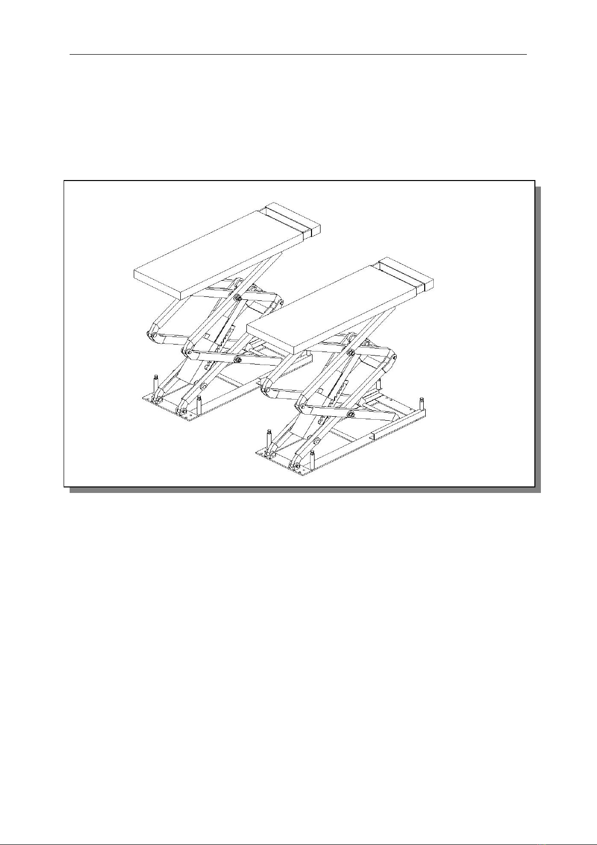
Small scissor Lift
LJS6035
USER’S MANUAL
Manufacturer:

USER’S MANUAL
2
MANUFACTURER AND SERVICE AGENT
HYDRAULIC AUTOMOBILE LIFT
MODEL:
Serial No.:
Year of manufacture:
Manufacture:
Name:
Address:
Tel:
Fax:
http:
E-mail:
AUTHORIZED SERVICE CENTRE:

USER’S MANUAL
3
Contents
Contents
Manufacture and service
Packing, transport and storage
Introduction
⚫Description of the machine
⚫Technical specifications
⚫Safety
⚫Installation
⚫Debugging
⚫Operation
⚫Maintenance and care
⚫Troubleshooting
⚫Accessory
USER’S MANUAL
4
PACKING, TRANSPORT AND STORAGE
ALL PACKING, LIFTING, HANDLING, TRANSPORT AND UNPACKING OPERATIONS
ARE TO BE PERFORMED EXCLUSIVELY BY EXPERT PERSONNEL
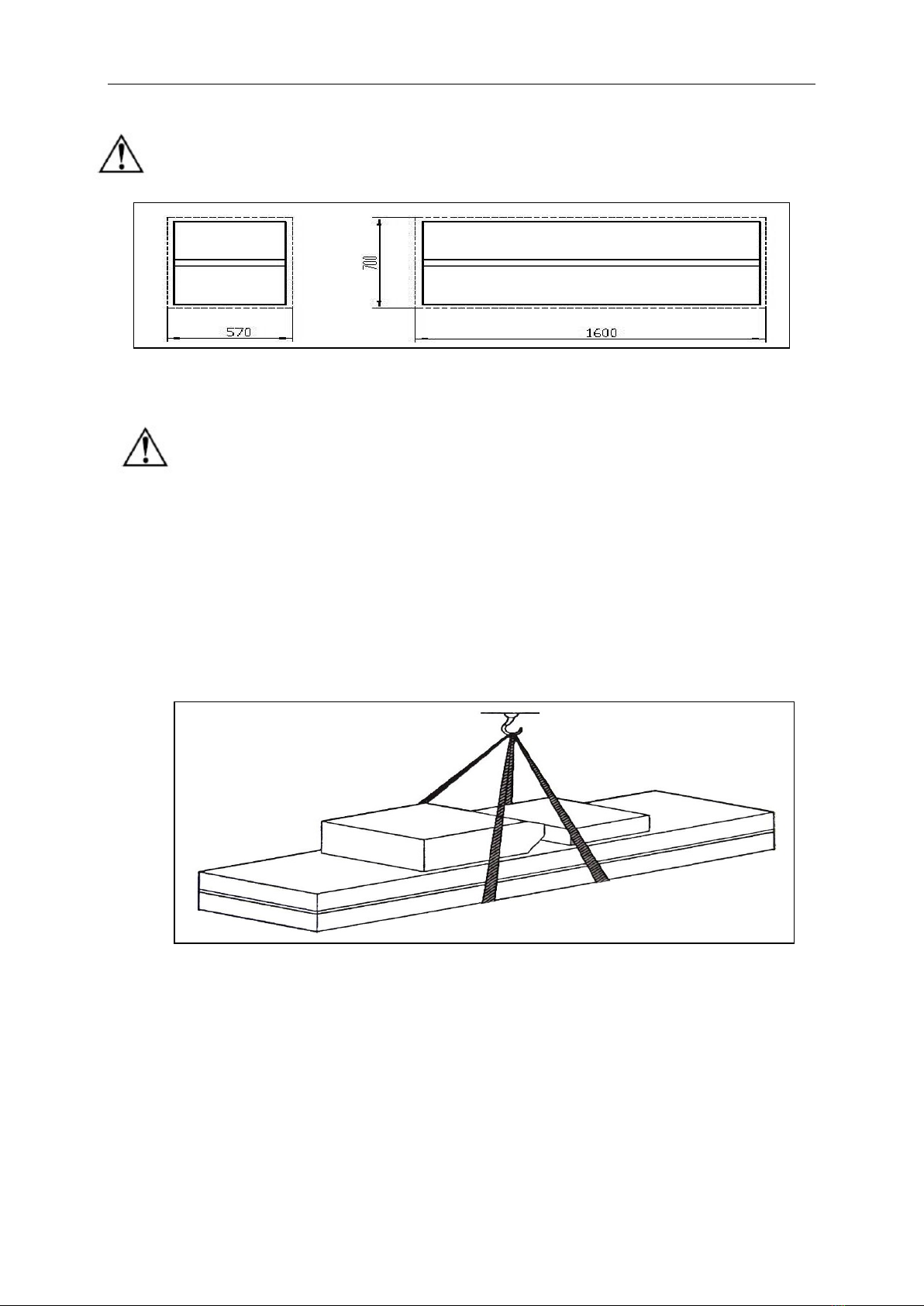
Packing dimension picture
Transport
Packing can be lifted or moved by lift trucks, cranes or bridge cranes. In case of slinging,
a second person must always take care of the load, in order to avoid dangerous
oscillations
.During loading and unloading operation, goods must be handled by vehicles or ships.
At the arrival of the goods, verify that all items specified in the delivery notes are included. If finding
missing parts, possible defects or damage due to transport, one should examine damaged cartons according
to “Packing List” to verify the condition of damaged goods and missing parts, also the person in charge or
the carrier must be immediately informed.
The machine is heavy goods! Don’t take manpower load and unload and transporting way into
consideration, the safety of working is important.
Furthermore, during loading and unloading operation goods must be handled as shown in the picture.
(Picture 2)
Storage:
-The machine equipment should be stocked in the warehouse, if stocked outside should do the disposal well
of waterproof.
-Use box truck in the process of transport, use container storage when shipping.
-The control box should be placed perpendicularly during the transport; and prevent other goods from
extrusion.
-The temperature for machine storage: -25ºC-- 55ºC
Picture 1 (packing dimension)
Picture 2(Goods-lifted)

USER’S MANUAL
5
Manual Introduction
This manual has been prepared for workshop personnel expert in the use of the lift operator and
technicians responsible for routine maintenance fitter.
Workers should read the “User’s Manual” carefully before carrying out any operation with the lift.
This manual contains important information regarding:
-The personal safety of operators and maintenance workers;
-Lift safety;
-The safety of lifted vehicles;
CONSERVING THE MANUAL
This manual is an integral part of the lift.
The manual must be kept in the vicinity of the lift, so that the operator and maintenance staff must
be able to locate and consult the manual quickly and at any time.
Attentively reading Chapter 3, which contains important information and safety warning, is particularly
recommended.
The lift is designed and manufactured according to European Standard
The lifting, transport, unpacking, assembly, installation, starting up, initial adjustment and testing,
extraordinary maintenance, repair, overhauls, transport and dismantling of the lift must be
performed by specialized personnel from the licensed dealer authorized by the manufacturer.
The manufacturer declines all responsibility for injury to persons or damage to vehicles or objects when
any of the above mentioned operations has been performed by unauthorized personnel or when the rack has
been subject to improper use.
This manual indicates: the operative and safety aspects that may prove useful to the operator and
maintenance worker. For better understanding the structure and operation of the lift and for best
use of the same, workers must read the “Maintenance & Use Manual” carefully before carrying
out it.
In order to understand the terminology used in this manual, the maintenance and repair activities, the ability
to interpret correctly the drawings and descriptions contained in the manual and be the country in which the
machine has been installed.
The same applies to the maintenance and the maintenance fitter must also possess specific and specialized
knowledge both in mechanical and engineering field.
⚫OPERATOR: person authorized to use the lift
⚫MAINTENANCE FITTER: person authorized for routine maintenance of the lift.
Manufacturer owns the right to make little change for the manual owing to the improvement of
technology.
Table of contents


