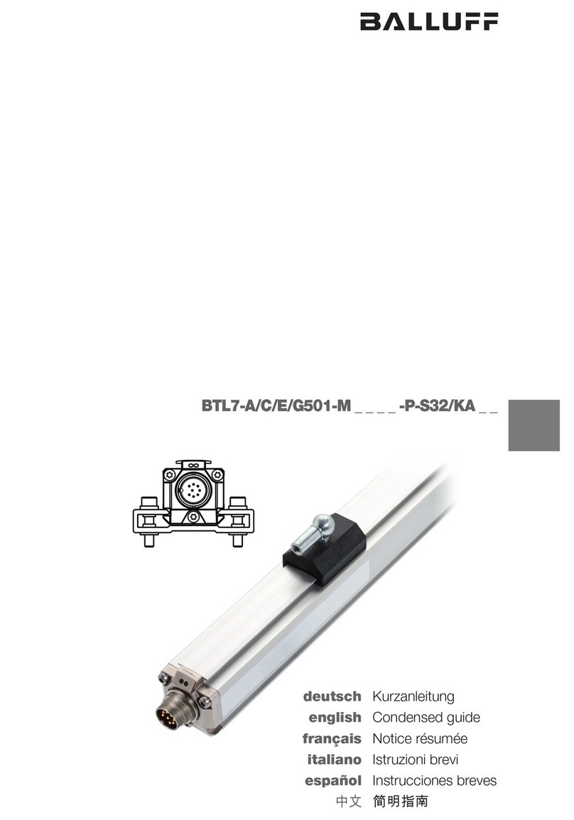
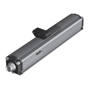
DATUM ELECTRONICS M425 User manual

DATUM ELECTRONICS
M425 TORQUE TRANSDUCER
HANDBOOK AND INSTALLATION GUIDE
DATUM ELECTRONICS LIMITED TELEPHONE: +44 (0) 1983 28 28 34 FAX: +44 (0) 1983 28 28 35 EMAIL: [email protected] WEB: www.datum-electronics.co.uk

DATUM ELECTRONICS M425 TORQUE TRANSDUCER HANDBOOK
2
CONTENTS
M425 INTRODUCTION 3
What is it designed to do? 3
SYSTEM ADVANTAGES 3
M425 system performance and benefit: 3
SYSTEM OUTLINE 3
The key features of the M425 system 3
System items supplied 3
Check list 3
Included as standard with the M425 3
Optional extras available from Datum Electronics 3
FAMILIARISATION 4
Simple diagnostics, testing and connection 4
MECHANICAL INSTALLATION 5
Objective of the mounting 5
Things to avoid 5
Which way round to mount? 6
Keyway fit size 6
Anti-rotation point 6
ELECTRICAL CONNECTION 7
Cable and socket connectors wiring guide 7
SYSTEM DIAGRAM 8
USER INTERFACES 9
Universal interface 9
Graphic user interface 9
Versatile bulkhead mounted indicator 10
Alternate connection options 10
DATA OUTPUT 11
The M425 Transducer - 3 operational modes 11
Data output format 11
Raw data torque calculation 11
Software commands direct to the M425 stator 11
How checksum is calculated 12
Sample rates and resolution 12
PC port limitations 12
OUTPUT PERFORMANCE 13
Maximum sample rates 13
OUTPUT DATA 14
Read more from your data 14
SPECIFICATIONS 15
M425 performance information 15
M425 shaft stiffness and load parameters 16
M425 mass and dimensions (mm) 17
PRE-CALIBRATED AND TESTED 18
Test certificate 18
ALTERNATIVE SOLUTIONS 18
The Datum RS & FF425 ranges 18
DIAGNOSTICS 19
Guide to status codes 19
MAINTENANCE 20
Serviceable items: Bearings 20
GLOSSARY OF TERMS 20
Document: 1010 Issue: 1 Date: 17/2/2014

DATUM ELECTRONICS M425 TORQUE TRANSDUCER HANDBOOK
3
SYSTEM OUTLINE
The key features of the M425 system are:
SYSTEM ADVANTAGES
M425 system performance and benefits:
M425 INTRODUCTION
What is it designed to do?
The latest technology Datum Electronics Series M425
non-contact rotary Torque Transducers have been designed
to fit with most applications and solutions requiring rotary
torque measurement. The Torque Transducer fits in line with
the drive train or test bed, using standard keyway shafts.
A non-contact transmission system provides data directly
proportional to torque. In this variant it is supplied as a
complete transducer with bearings to support the stator unit
on the rotating shaft. It is suitable for most general test rig
applications.
The M425 Torque Transducer utilises a strain gauged shaft
for accurate and reliable torque measurement and a set
of rotating on-shaft conditioning electronics. The digital
signals are transmitted to the non-rotating part of the system
or stator providing a reliable and highly accurate torque
measurement solution.
The M425 has a torque measuring element design with an
optimum length to maximise overall accuracy and give a high
degree of tolerance to mounting offset.
The M425 also has a legacy mode so that it can be used as a
direct replacement for the previous M420 Transducer. CHECK LIST
Included as standard with the M425 Torque
Transducer:
DESCRIPTION QUANTITY
1 - M425 Torque Transducer 1
2 - M425 handbook 1
3 - Quick-start guide 1
4 - Test certificate 1
5 - Datum software 1
6 - Transducer cable 1
7 - Power supply 1
Optional extras available from Datum Electronics:
DESCRIPTION
Universal Interface
Versatile bulkhead mounted indicator
M425 Transducer to universal interface data cable
SYSTEM ITEMS SUPPLIED
It is recommended that all hardware, consumables, tools and
software are checked and present before preparation and
installation commences.
5
1
24
3
M425
Handbook
Quick-Start
Guide
Test
Certificate
Accuracy and resolution options
High data rate
Static and rotary torque measurement
Operational stability
Non-contact data transmission
Magnetic speed sensor - not effected by dirt
Simple to integrate
Robust construction
Torque transducer sensor
Ranges 0-5Nm up to 0-60,000Nm
High resolution torque sampling
Sample rate selection 1-4000 samples per second
Low power consumption
Complete torque transducer
Designed to be mounted in line with the drivetrain
Torque transducer body supported on rotary shaft
with bearings
Ideal for test rig applications
Keyway shaft for easy fit and rig design
Torque measurement available up to 60,000Nm
in a range of model sizes
Analogue output options
7
6

DATUM ELECTRONICS M425 TORQUE TRANSDUCER HANDBOOK
4
FAMILIARISATION
SIMPLE DIAGNOSTICS, TESTING
AND CONNECTION
Before installing your M425 Transducer into the rig or
machine we would advise you to familiarise yourself with its
connections and operation by performing a bench test.
By connecting the Transducer directly to a Datum Universal
Interface (example A below), or to a PC via the Datum
Universal Interface (example B opposite), you will be able
to rotate the shaft to generate an output signal of RPM. By
applying a small torque by hand to the shaft you will also
be able see the change in the torque signal output on the
Universal Interface display or in the Datum Data Logging
PC software.
If you are connecting to a PC without a Datum Universal
Interface and using your own instrumentation (example C
opposite) you will be able to test your instrumentation in the
same way by simulating a signal to the interface or indicator
model you are using. The M425 supports a variety of
universal interface models.
Once you are familiar with the transducer and its outputs
continue to install as normal. If any questions arise at this
stage please call our product support team for advice.
The Datum Universal Interface display
The Datum Universal Interface has a built-in display which
you can use for familiarisation with a direct connection to the
M425 Torque Transducer (diagram A below).
Connection example (A)
M425 to the Datum Universal Interface.
Connection example (B)
M425 to PC via the Datum Universal Interface.
Connection example (C)
Direct connection from M425 to an alternative
interface or indicator.
See electrical connection guide on page 7 for further
information on connecting your own instrumentation.
+12Vdc supply
Supply ground
RS485 A: -ve data
RS485 B: +ve data
RS232 TX/RX (option)
Diagram No. 3Diagram No. 1
Ethernet/USB
Diagram No. 2
M425
PC
M425
M425
Universal
Interface
Universal
Interface
Main power
input
Optional power supply:
15-24V dc 500mA
Main power
plug input
Optional power supply:
15-24V dc 500mA
The Universal
Interface display can
show the following
data from the M425
Torque Transducer:

DATUM ELECTRONICS M425 TORQUE TRANSDUCER HANDBOOK
5
MECHANICAL
INSTALLATION
OBJECTIVE OF THE MOUNTING
The objective is to align the shaft of the M425
Torque Transducer (sensor) with the torque.
The torque should where possible be driven
through the centre line of the shaft.
Unlike Disk Transducers that require very fine alignment
tolerances when mounting, the M425’s longer shaft allows
a greater degree of flexibility in terms of alignment.
M425 Torque
Transducer
Anti-rotation
point
Securing
post
Load pumpEngine
Bearing Bearing
Keyway couplings
Plummer blocks
or suported bearings
Data output
cable
Typical installation with bearing block each side
THINGS TO AVOID Overload = 150% the rating of the transducer. Loads at this
level should be avoided as they will decrease the fatigue life
of the Transducer. If you are likely to see large overloads at
the same time as wishing to see high resolution data for much
smaller torques please consult our sales team.
Ultimate Load = at the ultimate loads quoted for the
Transducer shaft (see table 8, page 16) the sensing element
will be damaged and large offsets will occur. At this level
the shaft will be well beyond its design limits and may
mechanically fail. If you have loaded a Transducer above
the Proof Load/Overload level it should be checked before
continued use.
Diagram No. 4
The series M425 Torque Transducers are designed
to withstand a level of overload.
The load levels quoted within tolerances (see table 8 on
page 16) should not have any effect on the calibration or
zero setting of the Transducers. Each Transducer has been
subjected to the proof load level within its testing cycle.
Loading the Transducer above the proof level will offset the
Transducer zero and will damage the Transducer. Regular
loading beyond the proof level will start to show progressive
zero movement and may effect both the gain and the
hysteresis of the Transducer. The shaft absolute load is the
maximum before the shaft will yield.
You should avoid any side loads or bending loads across
the shaft. As the M425 Transducer series have relatively
long shafts they are more tolerant to a small degree of
misalignment than short flange transducers (sensors), however
misalignment can change the loading on the internal bearings
of the device and should be avoided where possible.
Consider large dynamic or transient torques when
designing your test system.
When designing the test rig or test system that will use the
M425 Transducer you should consider the effect of any large
inertial / kinetic loads such as flywheels or brakes. If the
system is to drive to a high level of torque, and then a brake is
applied, the dynamic torque in the test rig can be much higher
than that of the output of the drive motor. The fast deceleration
torque may exceed the limits above causing damage.
Bent shaft
Offset shaft
Centre line shaft alignment
Diagram No. 5
Correct alignment indicated
above with the load running
through the centre of the shaft.
Avoid misalignment and side
loads or bending loads as
indicated on the right.
Where the installation will see a larger degree of misalignment
you should consider the use of flexible couplings in the
drive line. If misalignment is very likely consider the Datum
Electronics RS and FF ranges which are bearing-less
transducers (see page 18). Talk with our sales team who can
advise on this type of installation.

DATUM ELECTRONICS M425 TORQUE TRANSDUCER HANDBOOK
6
ANTI-ROTATION POINT
The M425 Transducers have an anti-rotation anchor
point on the underside of their casing. This is to be
used to secure the static body of the Transducer
and prevent rotation during operation.
Pass a strong cable or tie through the hole in the anti-rotation
anchor point and secure the tie to a solid structure on the test
rig, ensuring the tie has clearance from the rotating drive shaft
and moving parts to avoid snagging.
You should use the anti-rotation anchor point for this rather
than the data cable as using the data cable may damage the
connection. The data cable is not designed to take a load.
Cable tie
or lanyard
WHICH WAY ROUND TO MOUNT?
The M425 Transducer will operate in both a
clockwise or anti-clockwise direction.
The M425 Transducer is calibrated to give a positive output
for clockwise torque and a negative output for counter
clockwise torque. The M425 Transducer will also output
torque data while static.
KEYWAY FIT SIZE
Drive end
This indicates a clockwise
rotation producing a
positive output signal
Load end
Note alignment
position of output
socket is nearest
the drive end
Keyway sizes are
generally in accordance
with BS4235-2:1977.
See table No. 9 on page
17 for the keyway size
options available on the
M425 model range.
Diagram No. 8
Diagram No. 6
Diagram No. 7

DATUM ELECTRONICS M425 TORQUE TRANSDUCER HANDBOOK
7
ELECTRICAL
CONNECTION
CABLE AND SOCKET
CONNECTORS WIRING GUIDE
The M425 Transducer is supplied with a standard 3 metre
signal cable. This cable is terminated with a standard
9-way D connector to interface to any of the Datum
Electronics Signal Interfaces or Indicators.
The connections within this cable are detailed below should
you wish to connect the M425 Transducer directly into your
own instrumentation and software.
The default signal output from the Transducer is RS485 Serial
Data (see protocol section for data output details on page 11).
We have also provided the Triad 4-way plug wiring
arrangement in diagram No. 10 below for the Transducer end
of the cable. On some occasions a cable may need to be
assembled after laying through tight bulkhead access which
may require the removal of the connectors.
The maximum cable length for the M425 Transducer is
normally 200 metres. For special applications with the right
cable conditions this can increase to 500 metres depending
on the sample rate and baud rate.
The data cable from the M425 Transducer to an interface
must meet the following specification: 4 core wire, braided,
screened, 7/02mm PVC Sheathed cable or equivalent.
The M425 Transducer current consumption is less than
250mA with a 12Vdc supply. The M425 Transducer complete
with its Universal Signal Interface will consume below 450mA.
Note: alignment
notch at top of
contact carrier
Max Cable length = 200m
Pins out
Pins solder side
Shielding
Multi-core
cable
To M425 Torque
Transducer
Pins solder side
Solder
shielding
to tab
Shielding
To Universal
Interface
Male plug connector
Triad T01-550-P04
Female 9 PIN
D Connector RS485
Triad 4-way Plug T01-550-P04 wiring guide 9-way D connector RS485 wiring guide
Diagram No. 9
Pin Out Function Cable Colour
Pin 1 +12Vdc supply
to Transducer
RED
Pin 2 Supply ground BLUE
Pin 3 RS485 A: -ve data YELLOW
Pin 4 RS485 B: +ve data
RS232 TX/RX (option)
GREEN
PIN numbering viewed
from solder/cable side
of the connector
Pin Out Function Cable Colour
Pin 1 RS485 A: -ve data YELLOW
Pin 2 RS485 B: +ve data
RS232 TX/RX (option)
GREEN
Pin 5 Supply ground BLUE
Pin 9 +12Vdc supply
to Transducer
RED
PIN numbering viewed
from solder/cable side
of the connector
Diagram No. 10 Diagram No. 11
5
31
42
2
9
1
5
31
42
2
9
1
Transducer signal cable wiring guide

DATUM ELECTRONICS M425 TORQUE TRANSDUCER HANDBOOK
8
SYSTEM CONNECTIONS
When supplied with the Universal Transducer Interface the
Datum M425 Torque Transducers provide simple connections
to logging, monitoring and control system through both
analogue and serial interfaces. Software is provided to access
the primary Ethernet setup interface for the M425.
*The 12V Output and the Serial IN Copy are screw
terminals that duplicate the connections for the serial
torque sensor ‘D’ connector.
**Alternative power input terminal.
Serial Torque Sensor
Factory Reset
Zero Reset
Ethernet
USB Type A - Data Logging
USB Mini B - Primary USB to PC
InterfaceMain Power Input
Serial Output
Diagram No. 13
Universal Interface connections guide
Power Analogue (2 way)
Speed Analogue (2 way)
Torque Analogue (2 way)
Thrust Analogue (2 way)
*12 Volts OUT (2 way)
*Serial IN copy (2 way)
Tacho Pulse IN (3 way)
Power LED (2 way)
15V - 24V OUT (2 way)
**15V - 24V Power IN (2 way)
Front
Back
Ethernet/USB
PC
Diagram No. 12
M425
M425 Transducer, Universal Interface
and PC connections guide
Universal
Interface
Main power
plug input
Optional power supply:
15-24V dc 500mA

DATUM ELECTRONICS M425 TORQUE TRANSDUCER HANDBOOK
9
UNIVERSAL INTERFACE
The universal interface will connect directly to the M425
Torque Transducer. It supplies 12Vdc to power the Transducer
and converts the torque and RPM signal into the outputs
you require.
4 analogue outputs as either 4-20mA (4-12-20mA):
+/-10Vdc, +/-5Vdc, 0-10Vdc or 0-5Vdc, for shaft torque,
RPM, Power and Spare
RS485/RS232 serial data
Ethernet
MODBUS
USB Type Mini B
The interface will also accept an input from an external
tachometer sensor, the output from this sensor can be
directly linked into the torque and power data.
USER INTERFACES
The outputs that can be configured are:
Datum data logging software
The Datum data logging and
configuration software provides a wide
range of control functions of the M425
including set-up and configuration
options plus data logging.
GRAPHIC USER
INTERFACE
Datum Electronic’s Universal Interface provides
options for different operating environments.
Datum Electronics can provide the universal interface
package for either control enclosure application or heavy
industrial applications.

DATUM ELECTRONICS M425 TORQUE TRANSDUCER HANDBOOK
10
VERSATILE (400260)
BULKHEAD MOUNTED INDICATOR
Designed for use in industrial and marine environments
the Heavy Duty Indicator provides all of the facilities of the
Universal Indicator plus an extended graphical display.
It is housed in a weatherproof enclosure with waterproof
protector glands & connector and is designed to meet IP67
ingress protection standard.
ALTERNATE CONNECTION OPTIONS
The M425 is compatible with a variety of other universal
interfaces or indicators by correct cable and PIN
configuration. This allows direct connection to their user
software and customers own software. See page 7 for a
guide to wiring connector configuration.
The M425 will also accept configuration commands to enable
connection to legacy Datum Electronics interfaces and
indicators. When set in compatibility mode the M425 can be
used with Torque Log Software, the Datum Electronics type
300 and Type 370 Indicators and the Type 400150 USB /
analogue or 400152 USB interfaces.

DATUM ELECTRONICS M425 TORQUE TRANSDUCER HANDBOOK
11
DATA OUTPUT
Data output from the Datum M425 series is available
is either readable ASCII or Hex formats. This allows
a wide range of interface options using either
the Datum Interfaces or Software or even simple
terminal programs to read the data.
THE M425 TRANSDUCER HAS
THREE OPERATIONAL MODES:
MODE 1: In this mode the Transducer will transmit Zeroed
data in the format of the $ZR strings below.
$ZR,0.0002,0.0002,0.0002,0.0002,0.0002,0.44,CS
The number of torque values per second
(resolution) can be varied by setting the baud rate
either through the Datum PowerKit software or by
using the “baud” command if using your
own software.
MODE 2: Mode 2 is a non-transmit mode and will only
respond to commands. Sending a “help” command
in this mode will list the commands available.
MODE 3: This is a legacy binary mode in which the
transducer will transmit the 6-byte binary format
used in earlier Datum products and the M420.
The mode can be set using the Datum PowerKit
software or the command “mode” when using your
own software. See the following section for more
information on command options.
DATA OUTPUT FORMAT:
The Series M425 Transducer can provide data either as an
individual reading or as parts of data packets. These can
be configured using the interface software to suit most
applications.
The following two standard formats (String type A and String
type B) are provided as a guide:
String type A
$ZR,0.0492,25.6,CS
Where:
$ZR is the string identifier,
0.0492 is the mV/V value from the sensor,
25.6 is the RPM,
CS is the data checksum
This type of string containing multiple mV/V signal value is
used where the baud rate of the receiving device is limited
and a higher data rate is required.
String type B:
$ZR,0.0492,0.0492,0.0492,0.0492,0.0492,0.0492,0.0492,0.0492,
0.0492,0.0492,24.1, 21.6,CS
Where:
$ZR is the string identifier,
0.0492 are the last 10 signal values in mV/V from the sensor,
25.6 is the RPM,
21.6 is the shaft temperature indication,
CS is the data checksum.
This type of string containing multiple mV/V signal value is used
where the baud rate of the receiving device is limited and a higher
data rate is required.
RAW DATA TORQUE CALCULATION:
i.e. 1.7560 mV/V = 500Nm (see calibration certificate for this value)
the torque will be [0.0492 ÷ 1.7650 x 500] Nm = 14.00Nm.
SOFTWARE COMMANDS DIRECT
TO THE M425 STATOR:
The following commands can be used with your own software to
configure the M425 Transducer and set the data output.
“Detail” returns the following string format:
$DT, 0.0001,-0.0015,0.0015,0.00, 21.132,
4.995,0.175,CS
The string format is made of the following
data elements:
$DT is the identifier,
0.0001 is the zeroed strain,
-0.0015 is the raw strain mV/V,
0.00 is the RPM,
21.312 is the rotor temperature deg C,
4.995 is the rotor voltage,
0.175 is the power supply current,
CS is the checksum.
“Baud” sets the host baud rate and reboots the system.
“Offset” signed offset in nV/V applied to the rotor output.
“Gain” signed gain in pV/V/quanta.
“Mode” 1= Normal.
2= Command mode.
3= Compatibility mode.
“Normal” start Transmission of rotor data string $RZ.
“Help” lists the commands available in this mode.
“Reset” resets the Transducer to a default setting of
(56700 baud, 1 torque value, 1 RPM value,
128 samples per second, mode 2
[awaiting a command]).

DATUM ELECTRONICS M425 TORQUE TRANSDUCER HANDBOOK
12
HOW CHECKSUM IS CALCULATED:
The checksum is calculated and implements the CCITT 16-bit
CRC used by IEEE 802.15.4, using a Modulo 256 calculation.
A detailed description and software examples are available in
Technical Bulletin 1007.
SAMPLE RATES AND RESOLUTION
The M425 can output torque data at sample rates from 4 up
to 4000 samples per second. The lower data rates provide
resolution up to 1:560,000, at highest data rates the noise free
resolution reduces 1:11,000. See table 3 on page 13.
The sample rates that can be transmitted from the stator
to your instrumentation or computer are listed in tables 1
and 2 on page 13. These table show the rates for a range of
standard output strings.
PC PORT LIMITATIONS:
Note: the M425 Transducer is capable of transmitting at the
rates above. Some PC’s have limited port configurations that
may not be able to cater for data rates at this level.
The maximum data rate at a given baud rate can be
calculated as: The basic string with a single torque value and
an RPM value has 22 characters, each character is 10 bits.
Therefore running serial communications at 9600 baud you
are limited to 43 samples per second (9600 ÷ (22 x 10).
By running at 115,200 baud this is increased to 525 samples
per second [115,200 ÷ (22 x 10)].
By sending the data in packets containing 10 torque values
the message becomes 94 characters long [115,200 ÷ (94
x 10)] as each packet contains 10 samples. The data rate
becomes 1225 samples per second.

DATUM ELECTRONICS M425 TORQUE TRANSDUCER HANDBOOK
13
OUTPUT PERFORMANCE
Key to a Zeroed Data MODE 1
example output data string
(for 10 torque readings per data packet)
$ZR,T,T,T,T,T,T,T,T,T,T,R,V,CS
$ZR = String type identifier
(Zeroed Torque in mV/V)
T = Torque, raw strain data
readings in mV/V
R = Rotor shaft RPM
CS = Checksum
1:1000
1:10000
1:100000
1:1000000
110 100 1000
Output Samples Per Second
Noise-free
Resolution
Based on 16bit strain/torque samples, resolution of 1:20,000 (inc. RPM)
At a Baud rate of:
9600 19200 38400 57600 115200 256000 460800 921600 3000000
Number of torque values: Torque readings per second: Example of the output string:
Type 1 = 1 per packet 45 91 182 274 548 1219 2000 4000 4000 $ZR,T,R,C,V,CS
Type 2 = 5 per packet 97 195 391 587 1175 2000 4000 4000 4000 $ZR,T,T,T,T,T,R,V,CS
Type 3 = 10 per packet 114 228 457 685 1250 2000 4000 4000 4000 $ZR,T,T,T,T,T,T,T,T,T,T,R,V,CS
Type 4 = 16 per packet 121 243 487 731 1250 2000 4000 4000 4000 $ZR,T,T,T,T,T,T,T,T,T,T,T,T,T,T,T,T,R,V,CS
Table No. 2
Table No. 3
Based on 24bit strain/torque samples, resolution of 1:2,000 (inc. RPM)
At a Baud rate of:
9600 19200 38400 57600 115200 256000 460800 921600 3000000
Number of torque values: Torque readings per second: Example of the output string:
Type 1 = 1 per packet 43 87 174 260 525 1100 2000 4000 4000 $ZR,T,R,C,V,CS
Type 2 = 5 per packet 88 177 355 533 1066 2000 4000 4000 4000 $ZR,T,T,T,T,T,R,C,V,CS
Type 3 = 10 per packet 102 204 408 612 1225 2000 4000 4000 4000 $ZR,T,T,T,T,T,T,T,T,T,T,R,C,V,CS
Type 4 = 16 per packet 108 216 432 649 1250 2000 4000 4000 4000 $ZR,T,T,T,T,T,T,T,T,T,T,T,T,T,T,T,T,R,C,V,CS
Table No. 1
MAXIMUM SAMPLE RATES FOR TYPICAL
OUTPUT DATA STRING INCLUDING RPM
Resolution table
This graph show the noise-free resolution attainable at different output data rates.
PC Port Limitations
Note: the M425 Transducer is capable of
transmitting at the rates above. Some PC’s
have limited port congurations that may not
be able to cater for data rates at this level.
When the interface is transmitting a standard data packet containing
one torque sample per packet the minimum baud rates required to
transmit/receive the data are shown below.
Lower baud rates can be used if the data is combined in data packets
containing more than one torque reading (see the table below which
outline the maximum sample rates at given baud rates)
Samples per second 100 1000 2000 4000
Minimum Baud Rate 38400 256000 460800 921600

DATUM ELECTRONICS M425 TORQUE TRANSDUCER HANDBOOK
14
OUTPUT DATA
READ MORE FROM YOUR DATA
The M425 will provide you with accurate torque data.
The following graphs show examples of some data
output possibilities of the M425 Torque Transducer.
$ZF -0.0778 -0.0772 -0.0772 -0.0775 -0.0773 -0.0776 -0.0773 -0.0776 -0.0771 -0.0776 -0.0775 -0.0776 -0.0778-0.0773 -0.0773 -0.0774 5.4E+08 134 *1e
$ZF -0.0732 -0.0734 -0.0737 -0.0734 -0.0735 -0.0736 -0.0734 -0.0735 -0.0732 -0.0734 -0.0735 -0.0732 -0.0731-0.0734 -0.0733 -0.0736 5.6E+08 179 *ea
$ZF -0.0733 -0.0733 -0.0733 -0.0735 -0.0736 -0.0734 -0.0734 -0.0739 -0.0738 -0.0736 -0.0736 -0.0739 -0.0734-0.0737 -0.0738 -0.0735 5.6E+08 180 *ed
$ZF -0.0733 -0.0736 -0.0736 -0.0736 -0.0736 -0.0739 -0.0737 -0.0739 -0.0739 -0.0737 -0.0739 -0.0741 -0.074 -0.0737 -0.0739 -0.0738 5.6E+08 181 *ff
$ZF -0.0736 -0.0736 -0.0743 -0.0739 -0.0741 -0.0738 -0.074 -0.0739 -0.0736 -0.0737 -0.0738 -0.0739 -0.0737-0.0737 -0.0739 -0.074 5.6E+08 182 *01
$ZF -0.0735 -0.0736 -0.074 -0.0738 -0.074 -0.0736 -0.0737 -0.0736 -0.0737 -0.0737 -0.0734 -0.0736 -0.0736-0.0736 -0.0736 -0.0734 5.6E+08 183 *f2
$ZF -0.0737 -0.0737 -0.0735 -0.0738 -0.0736 -0.0737 -0.0733 -0.0736 -0.0735 -0.0736 -0.0736 -0.0736 -0.0734-0.0733 -0.0734 -0.0734 5.6E+08 184 *f4
$ZF -0.0734 -0.0732 -0.0734 -0.0739 -0.0736 -0.0733 -0.0734 -0.0735 -0.0734 -0.0735 -0.0731 -0.0737 -0.0732-0.0735 -0.0734 -0.0736 5.6E+08 185 *d9
$ZF -0.0733 -0.0737 -0.0733 -0.073 -0.0731 -0.0733 -0.0734 -0.0736 -0.0731 -0.0733 -0.0736 -0.074 -0.0735-0.0734 -0.0737 -0.0734 5.6E+08 186 *e3
$ZF -0.0734 -0.0733 -0.0736 -0.0734 -0.0732 -0.0733 -0.0736 -0.0736 -0.0734 -0.0735 -0.0737 -0.0734 -0.0736-0.0733 -0.0734 -0.0734 5.6E+08 187 *e9
$ZF -0.0736 -0.0737 -0.0735 -0.0736 -0.0737 -0.0737 -0.0735 -0.0736 -0.0735 -0.0735 -0.0737 -0.074 -0.0736-0.0736 -0.0737 -0.0735 5.6E+08 188 *02
$ZF -0.0739 -0.0736 -0.0737 -0.0734 -0.0736 -0.0736 -0.0734 -0.0734 -0.0734 -0.0735 -0.0733 -0.0733 -0.0732-0.0736 -0.0734 -0.0735 5.7E+08 189 *f1
$ZF -0.0737 -0.0734 -0.0734 -0.0733 -0.0735 -0.0736 -0.0736 -0.0735 -0.0734 -0.0734 -0.0736 -0.0734 -0.0736-0.0736 -0.0736 -0.0736 5.7E+08 190 *e9
$ZF -0.0734 -0.0734 -0.0734 -0.0732 -0.0736 -0.0737 -0.0734 -0.0733 -0.0734 -0.0736 -0.0734 -0.0734 -0.0733-0.0733 -0.0734 -0.0734 5.7E+08 191 *e0
$ZF -0.0733 -0.0732 -0.0731 -0.0731 -0.0736 -0.0737 -0.0733 -0.0731 -0.0735 -0.0736 -0.0734 -0.0734 -0.0734-0.0734 -0.0734 -0.0734 5.7E+08 192 *d8
$ZF -0.0734 -0.0732 -0.0734 -0.0731 -0.0734 -0.0731 -0.0734 -0.0737 -0.0735 -0.0735 -0.0737 -0.0736 -0.0739-0.0734 -0.0737 -0.0736 5.7E+08 193 *f8
$ZF -0.0734 -0.0738 -0.0734 -0.0737 -0.0737 -0.0737 -0.0736 -0.074 -0.0738 -0.0736 -0.0739 -0.0733 -0.0736-0.0738 -0.0737 -0.0734 5.7E+08 194 *05
$ZF -0.0732 -0.0734 -0.0736 -0.0736 -0.0734 -0.074 -0.0735 -0.0739 -0.0736 -0.0739 -0.0734 -0.0734 -0.0737-0.0736 -0.0736 -0.0736 5.7E+08 195 *fc
$ZF -0.0738 -0.073 -0.0734 -0.0735 -0.0733 -0.0735 -0.0736 -0.0734 -0.0741 -0.0737 -0.0734 -0.0735 -0.0736-0.0737 -0.0734 -0.0735 5.7E+08 196 *f3
$ZF -0.0736 -0.0735 -0.0736 -0.0736 -0.0734 -0.073 -0.0734 -0.0737 -0.0737 -0.0734 -0.0735 -0.0734 -0.0734-0.0736 -0.0736 -0.0733 5.7E+08 197 *ec
$ZF -0.0736 -0.0733 -0.0736 -0.0736 -0.0734 -0.0735 -0.073 -0.0735 -0.0734 -0.0735 -0.0734 -0.0733 -0.0734-0.0734 -0.0734 -0.0731 5.7E+08 198 *f2
$ZF -0.0734 -0.0734 -0.0734 -0.0735 -0.0731 -0.0733 -0.0733 -0.0734 -0.0735 -0.0734 -0.0737 -0.0735 -0.0736-0.0737 -0.0735 -0.0734 5.7E+08 199 *f2
$ZF -0.0736 -0.0737 -0.0737 -0.0735 -0.074 -0.0736 -0.0734 -0.0734 -0.0739 -0.0735 -0.0739 -0.0736 -0.0734-0.0736 -0.0737 -0.0732 5.7E+08 200 *f0
$ZF -0.0737 -0.0736 -0.0731 -0.074 -0.0734 -0.074 -0.0736 -0.0739 -0.0738 -0.0735 -0.0735 -0.0738 -0.0734-0.074 -0.0737 -0.0738 5.7E+08 201 *e7
$ZF -0.0735 -0.0736 -0.0737 -0.0735 -0.0737 -0.0738 -0.0734 -0.0737 -0.0733 -0.0733 -0.0736 -0.0737 -0.0734-0.074 -0.0738 -0.0735 5.7E+08 202 *fa
$ZF -0.0733 -0.0736 -0.0736 -0.0739 -0.0737 -0.0736 -0.0731 -0.0734 -0.074 -0.0734 -0.074-0.0736 -0.0736-0.0737 -0.0734 -0.0735 5.7E+08 203 *e5
$ZF -0.0736 -0.0734 -0.0735 -0.0733 -0.0732 -0.0735 -0.0731 -0.0737 -0.0731 -0.0731 -0.0736 -0.0736 -0.0733-0.0735 -0.0736 -0.0738 5.7E+08 204 *eb
$ZF -0.0734 -0.0735 -0.0737 -0.0736 -0.0735 -0.0736 -0.0736 -0.0734 -0.0735 -0.0737 -0.0734 -0.0733 -0.0736-0.0733 -0.0737 -0.0736 5.7E+08 205 *ef
$ZF -0.0738 -0.0738 -0.0735 -0.0736 -0.0736 -0.0736 -0.0737 -0.0737 -0.0737 -0.0741 -0.0735 -0.0736 -0.0734-0.0736 -0.0739 -0.0738 5.7E+08 206 *07
$ZF -0.0735 -0.0736 -0.074 -0.074 -0.0743 -0.0743 -0.0742 -0.0748 -0.0747 -0.0748 -0.0747 -0.0746 -0.0749-0.0749 -0.0749 -0.0754 5.7E+08 207 *12
$ZF -0.0752 -0.0751 -0.0757 -0.0756 -0.0753 -0.0755 -0.0755 -0.0759 -0.076 -0.0759 -0.0757 -0.0756 -0.0757-0.0759 -0.0763 -0.0762 5.7E+08 208 *23
$ZF -0.076 -0.0762 -0.0762 -0.0765 -0.0759 -0.076 -0.076 -0.076 -0.076 -0.076 -0.076-0.0759 -0.0755-0.0757 -0.0759 -0.0756 5.8E+08 209 *06
$ZF -0.0756 -0.0755 -0.0751 -0.0755 -0.0752 -0.0752 -0.0752 -0.0749 -0.075 -0.075 -0.0749 -0.0751 -0.0752-0.0749 -0.0748 -0.0747 5.8E+08 210 *ef
$ZF -0.0745 -0.0747 -0.0749 -0.075 -0.0746 -0.0747 -0.0744 -0.0744 -0.0746 -0.0742 -0.0749 -0.0744 -0.0748-0.0745 -0.0744 -0.0743 5.8E+08 211 *fb
$ZF -0.0746 -0.0743 -0.0742 -0.074 -0.074 -0.0741 -0.0737 -0.0741 -0.0739 -0.0739 -0.074-0.0741 -0.074 -0.0739 -0.0736 -0.074 5.8E+08 212 *e0
$ZF -0.0742 -0.0743 -0.074 -0.0741 -0.0739 -0.0743 -0.0741 -0.0739 -0.0739 -0.0741 -0.0741 -0.0741 -0.0741-0.074 -0.0746 -0.0741 5.8E+08 213 *e4
$ZF -0.0744 -0.0747 -0.0746 -0.0746 -0.0743 -0.0749 -0.0746 -0.075 -0.0752 -0.0755 -0.0756 -0.0755 -0.0757-0.0759 -0.0762 -0.0763 5.8E+08 214 *05
$ZF -0.0769 -0.0768 -0.0768 -0.0767 -0.0769 -0.0769 -0.0774 -0.0774 -0.0775 -0.0772 -0.0779 -0.0779 -0.0783-0.0781 -0.0782 -0.0784 5.8E+08 215 *3a
$ZF -0.0782 -0.0779 -0.0784 -0.0784 -0.0786 -0.0788 -0.0786 -0.0781 -0.0787 -0.0785 -0.0782 -0.0781 -0.0782-0.0781 -0.078 -0.0778 5.8E+08 216 *32
$ZF -0.0775 -0.0776 -0.0776 -0.0775 -0.0773 -0.0773 -0.0767 -0.0768 -0.0767 -0.0763 -0.076-0.0763 -0.076 -0.0762 -0.0762 -0.0757 5.8E+08 217 *22
$ZF -0.0755 -0.0752 -0.0754 -0.0755 -0.0751 -0.0748 -0.075 -0.0747 -0.0744 -0.0749 -0.0747 -0.0746 -0.0746-0.0744 -0.0741 -0.0741 5.8E+08 218 *f4
$ZF -0.0741 -0.0743 -0.0744 -0.0744 -0.0744 -0.0747 -0.0745 -0.0746 -0.0744 -0.0743 -0.0744 -0.0747 -0.0746-0.0749 -0.075-0.075 5.8E+08 219 *ef
$ZF -0.0768 -0.077 -0.0771 -0.0774 -0.0773 -0.0774 -0.0778 -0.0778 -0.0775 -0.0778 -0.0779 -0.0781 -0.0781-0.0783 -0.0781 -0.0781 5.8E+08 221 *2b
$ZF -0.0781 -0.078 -0.0785 -0.0784 -0.0785 -0.0782 -0.0779 -0.078 -0.0781 -0.0779 -0.0779 -0.0778 -0.0776-0.0779 -0.0778 -0.0775 5.8E+08 222 *37
$ZF -0.0781 -0.0771 -0.0776 -0.077 -0.0768 -0.0768 -0.0772 -0.0772 -0.0769 -0.0766 -0.0769 -0.0766 -0.0763-0.077 -0.0767 -0.0764 5.9E+08 223 *15
$ZF -0.0762 -0.0759 -0.0764 -0.0761 -0.0763 -0.0761 -0.0762 -0.0761 -0.076 -0.0763 -0.076-0.0762 -0.0762-0.0762 -0.076 -0.0763 5.9E+08 224 *e2
$ZF -0.0763 -0.0763 -0.0765 -0.0763 -0.0763 -0.0762 -0.0764 -0.0762 -0.0759 -0.0763 -0.0765 -0.0765 -0.0763-0.0766 -0.0766 -0.0766 5.9E+08 225 *12
$ZF -0.0765 -0.077 -0.0767 -0.0766 -0.0769 -0.0769 -0.0773 -0.0776 -0.0773 -0.0773 -0.0771 -0.0771 -0.0774-0.0776 -0.0775 -0.0776 5.9E+08 226 *2d
$ZF -0.0778 -0.0775 -0.0781 -0.0778 -0.0778 -0.0779 -0.0776 -0.0781 -0.0784 -0.0782 -0.0782 -0.0784 -0.0784-0.0787 -0.0785 -0.0788 5.9E+08 227 *31
$ZF -0.0782 -0.0786 -0.0786 -0.0789 -0.0788 -0.0791 -0.0789 -0.0788 -0.0787 -0.0788 -0.0788 -0.0791 -0.0791-0.0791 -0.0787 -0.0788 5.9E+08 228 *50
$ZF -0.0791 -0.0791 -0.0792 -0.0794 -0.0792 -0.0791 -0.0791 -0.0788 -0.0787 -0.0788 -0.0791 -0.0789 -0.0786-0.0787 -0.0786 -0.0789 5.9E+08 229 *47
$ZF -0.0789 -0.0789 -0.0788 -0.0785 -0.0787 -0.0786 -0.0787 -0.0785 -0.0784 -0.0788 -0.0787 -0.0787 -0.0785-0.0784 -0.0786 -0.0787 5.9E+08 230 *55
$ZF -0.0787 -0.0786 -0.0784 -0.0788 -0.0782 -0.0785 -0.0787 -0.0789 -0.0785 -0.0786 -0.0788 -0.0789 -0.0781-0.0787 -0.0786 -0.0787 5.9E+08 231 *55
$ZF -0.0784 -0.0785 -0.0786 -0.0784 -0.0787 -0.0786 -0.0785 -0.0783 -0.0782 -0.0788 -0.0786 -0.0785 -0.0784-0.0782 -0.0786 -0.0785 5.9E+08 232 *3f
$ZF -0.0782 -0.0781 -0.0784 -0.0785 -0.0782 -0.0782 -0.0784 -0.0781 -0.0785 -0.0782 -0.0785 -0.0785 -0.0783-0.0783 -0.0784 -0.0784 5.9E+08 233 *1d
$ZF -0.0783 -0.0781 -0.0783 -0.0782 -0.0781 -0.0784 -0.0782 -0.0785 -0.0787 -0.0784 -0.0781 -0.0786 -0.0783-0.0784 -0.0781 -0.0783 5.9E+08 234 *24
$ZF -0.0781 -0.0782 -0.0783 -0.0782 -0.0784 -0.0787 -0.0782 -0.0784 -0.0782 -0.0782 -0.0783 -0.0785 -0.0785-0.0787 -0.0786 -0.0784 5.9E+08 235 *3b
$ZF -0.0785 -0.0784 -0.0784 -0.0787 -0.0791 -0.079 -0.0789 -0.0786 -0.0787 -0.0787 -0.0788 -0.0788 -0.079 -0.0789 -0.0789 -0.0788 5.9E+08 236 *50
$ZF -0.0788 -0.0785 -0.0789 -0.0795 -0.0791 -0.0791 -0.079 -0.0793 -0.0792 -0.0795 -0.0791 -0.079 -0.0789-0.0791 -0.0797 -0.0793 5.9E+08 237 *44
$ZF -0.0789 -0.0788 -0.0793 -0.0789 -0.0794 -0.0792 -0.0789 -0.0792 -0.079 -0.0792 -0.079-0.0791 -0.0789-0.0795 -0.079 -0.0789 5.9E+08 238 *49
$ZF -0.0791 -0.0787 -0.0791 -0.0789 -0.079 -0.0789 -0.0788 -0.0791 -0.0785 -0.0788 -0.0786 -0.0785 -0.0785-0.0784 -0.0782 -0.0786 5.9E+08 239 *46
$ZF -0.0787 -0.0785 -0.0786 -0.0782 -0.0785 -0.0784 -0.0783 -0.0781 -0.0784 -0.0782 -0.0784 -0.0779 -0.0782-0.0784 -0.0781 -0.0781 5.9E+08 240 *1d
$ZF -0.0784 -0.0781 -0.0779 -0.0783 -0.0783 -0.0781 -0.0778 -0.0779 -0.0778 -0.0781 -0.0778 -0.078 -0.0778-0.0781 -0.0784 -0.0781 5.9E+08 241 *41
$ZF -0.0779 -0.0781 -0.0781 -0.0774 -0.0778 -0.0779 -0.0778 -0.0779 -0.0783 -0.0782 -0.0779 -0.0782 -0.0779-0.078 -0.0781 -0.0782 5.9E+08 242 *33
$ZF -0.0782 -0.0785 -0.0782 -0.0784 -0.0784 -0.0784 -0.0784 -0.0783 -0.0784 -0.0784 -0.0782 -0.0787 -0.0787-0.0782 -0.0784 -0.0784 5.9E+08 243 *3c
$ZF -0.0786 -0.0785 -0.0785 -0.0787 -0.0788 -0.0789 -0.0787 -0.0787 -0.0789 -0.0788 -0.079-0.0788 -0.0788-0.0787 -0.079 -0.0787 5.9E+08 244 *55
$ZF -0.0787 -0.0787 -0.0789 -0.0787 -0.0785 -0.079 -0.0787 -0.0787 -0.0787 -0.0787 -0.0786 -0.0789 -0.0781-0.0786 -0.0784 -0.0784 5.9E+08 245 *44
$ZF -0.0783 -0.0786 -0.0787 -0.0781 -0.0788 -0.0786 -0.0784 -0.0786 -0.0781 -0.0784 -0.0781 -0.0782 -0.0782-0.0779 -0.0782 -0.0782 5.9E+08 246 *33
$ZF -0.078 -0.0784 -0.0776 -0.078 -0.0777 -0.0781 -0.0778 -0.0777 -0.078 -0.0779 -0.0779 -0.0776 -0.0775-0.078 -0.0775 -0.078 5.9E+08 247 *37
$ZF -0.0781 -0.0782 -0.0779 -0.0781 -0.0781 -0.0781 -0.0778 -0.0781 -0.0778 -0.0779 -0.0782 -0.0778 -0.0785-0.0781 -0.078 -0.0784 6.0E+08 248 *2e
$ZF -0.0781 -0.0784 -0.0782 -0.0785 -0.0781 -0.0784 -0.0783 -0.0787 -0.0785 -0.0785 -0.0787 -0.0788 -0.0788-0.0787 -0.0789 -0.0788 6.0E+08 249 *4d
$ZF -0.0787 -0.0787 -0.0789 -0.0791 -0.0789 -0.079 -0.0789 -0.079 -0.079 -0.079 -0.0789 -0.0788 -0.0792-0.079 -0.0789 -0.0792 6.0E+08 250 *38
$ZF -0.0789 -0.0791 -0.0791 -0.0791 -0.0791 -0.0789 -0.0791 -0.0789 -0.079 -0.0789 -0.0791 -0.0791 -0.0792-0.0791 -0.0789 -0.0789 6.0E+08 251 *3c
$ZF -0.079 -0.0786 -0.0791 -0.079 -0.079 -0.0784 -0.0787 -0.0788 -0.0788 -0.0789 -0.0784 -0.0789 -0.0787-0.0785 -0.0785 -0.0785 6.0E+08 252 *4c
$ZF -0.0783 -0.0785 -0.0787 -0.0787 -0.0784 -0.0787 -0.0787 -0.0785 -0.0785 -0.0784 -0.0788 -0.0788 -0.0784-0.0784 -0.0784 -0.0786 6.0E+08 253 *4f
$ZF -0.0783 -0.0785 -0.0788 -0.0786 -0.0784 -0.0784 -0.0783 -0.0785 -0.0784 -0.0785 -0.0781 -0.0786 -0.0787-0.0788 -0.0783 -0.0785 6.0E+08 254 *45
$ZF -0.0784 -0.0786 -0.0789 -0.0787 -0.0785 -0.0787 -0.079 -0.0787 -0.0788 -0.0789 -0.0788 -0.0786 -0.0789-0.0791 -0.0788 -0.0793 6.0E+08 255 *5c
$ZF -0.079 -0.079 -0.0793 -0.0792 -0.0795 -0.0791 -0.0791 -0.0795 -0.0789 -0.0792 -0.0789 -0.0795 -0.0792-0.0791 -0.0793 -0.0795 6.0E+08 0*d2
$ZF -0.0794 -0.0794 -0.0791 -0.0794 -0.0794 -0.0793 -0.0794 -0.0792 -0.079 -0.0795 -0.0792 -0.0795 -0.0792-0.0792 -0.0793 -0.0793 6.0E+08 1*bf
$ZF -0.0795 -0.0796 -0.0792 -0.079 -0.0794 -0.0789 -0.079 -0.0792 -0.0788 -0.0793 -0.0791 -0.0792 -0.0792-0.0789 -0.079 -0.0793 6.0E+08 2*b8
$ZF -0.0791 -0.0789 -0.0789 -0.0791 -0.0788 -0.0794 -0.079 -0.0786 -0.0785 -0.0788 -0.0791 -0.0791 -0.0787-0.0784 -0.0785 -0.0787 6.0E+08 3*d3
$ZF -0.0788 -0.079 -0.0791 -0.0787 -0.0785 -0.0788 -0.0784 -0.0789 -0.0788 -0.0789 -0.0787 -0.0788 -0.0782-0.0786 -0.0791 -0.0787 6.0E+08 4*dd
$ZF -0.0784 -0.0784 -0.0788 -0.0785 -0.0782 -0.0785 -0.0787 -0.0789 -0.0784 -0.0788 -0.0785 -0.0789 -0.0791-0.0788 -0.0788 -0.0785 6.0E+08 5*dd
$ZF -0.0787 -0.0788 -0.0789 -0.0788 -0.0789 -0.0791 -0.0792 -0.0789 -0.0792 -0.0791 -0.0789 -0.0791 -0.0788-0.0794 -0.0789 -0.079 6.0E+08 6*eb
$ZF -0.079 -0.079 -0.079 -0.0789 -0.0791 -0.0791 -0.0788 -0.0792 -0.0792 -0.0792 -0.0791 -0.0791 -0.079 -0.0794 -0.0793 -0.0789 6.0E+08 7*b8
$ZF -0.0792 -0.0793 -0.0788 -0.0791 -0.0792 -0.0791 -0.0794 -0.0791 -0.0791 -0.0792 -0.0789 -0.079-0.079-0.0791 -0.0792 -0.079 6.0E+08 8*bf
$ZF -0.0789 -0.0788 -0.0789 -0.0787 -0.0788 -0.0788 -0.0792 -0.0789 -0.079 -0.0788 -0.0786 -0.0787 -0.0789-0.079 -0.0788 -0.0791 6.0E+08 9*ec
$ZF -0.0787 -0.0784 -0.079 -0.0789 -0.0785 -0.0788 -0.0788 -0.0788 -0.0784 -0.0789 -0.0788 -0.0786 -0.0785-0.0787 -0.0788 -0.0787 6.0E+08 10 *14
$ZF -0.0789 -0.0785 -0.0787 -0.0787 -0.0785 -0.0787 -0.0785 -0.0785 -0.0782 -0.0785 -0.0786 -0.0787 -0.0785-0.0786 -0.0783 -0.0787 6.1E+08 11 *13
$ZF -0.0785 -0.0788 -0.0786 -0.0785 -0.0785 -0.0788 -0.0784 -0.0785 -0.0787 -0.0784 -0.0784 -0.0787 -0.0791-0.0788 -0.0789 -0.0788 6.1E+08 12 *13
$ZF -0.0789 -0.0788 -0.0788 -0.0789 -0.0788 -0.0789 -0.0785 -0.0788 -0.0791 -0.0792 -0.079-0.0788 -0.0789-0.0789 -0.0794 -0.0788 6.1E+08 13 *18
$ZF -0.0792 -0.0789 -0.0792 -0.0792 -0.0789 -0.0792 -0.0791 -0.0794 -0.0791 -0.0789 -0.0791 -0.0794 -0.0791-0.0789 -0.0789 -0.0789 6.1E+08 14 *09
$ZF -0.0788 -0.0791 -0.0788 -0.0794 -0.0791 -0.0788 -0.0787 -0.0789 -0.0792 -0.0789 -0.0788 -0.0791 -0.0789-0.0792 -0.0787 -0.0784 6.1E+08 15 *0f
$ZF -0.0788 -0.0786 -0.0788 -0.0789 -0.0787 -0.0788 -0.0788 -0.0784 -0.0787 -0.0786 -0.0788 -0.0791 -0.0788-0.0785 -0.0787 -0.0785 6.1E+08 16 *24
$ZF -0.0784 -0.0785 -0.0785 -0.0787 -0.0784 -0.0784 -0.0783 -0.0788 -0.0785 -0.0787 -0.0785 -0.0784 -0.0782-0.0787 -0.0785 -0.0787 6.1E+08 17 *0f
$ZF -0.0784 -0.0785 -0.0787 -0.0786 -0.0784 -0.0784 -0.0789 -0.0787 -0.0785 -0.0787 -0.0788 -0.0785 -0.0787-0.0788 -0.0785 -0.0793 6.1E+08 18 *1a
$ZF -0.0787 -0.079 -0.0785 -0.0789 -0.0789 -0.0785 -0.0787 -0.0787 -0.0788 -0.0788 -0.0789 -0.0786 -0.0789-0.0789 -0.0789 -0.0789 6.1E+08 19 *2d
$ZF -0.0788 -0.079 -0.0792 -0.079 -0.0788 -0.079 -0.0789 -0.0791 -0.0791 -0.0793 -0.0789 -0.0794 -0.0789-0.0789 -0.0791 -0.0791 6.1E+08 20 *06
$ZF -0.0789 -0.0792 -0.0791 -0.0791 -0.0788 -0.0791 -0.0791 -0.0792 -0.0788 -0.0791 -0.079-0.0786 -0.0791-0.079 -0.0788 -0.0794 6.1E+08 21 *f4
$ZF -0.0792 -0.0789 -0.0789 -0.0788 -0.0794 -0.0789 -0.079 -0.0791 -0.0788 -0.0789 -0.0789 -0.0789 -0.0789-0.0791 -0.079 -0.0787 6.1E+08 22 *1d
$ZF -0.0793 -0.0787 -0.0789 -0.0792 -0.0789 -0.0792 -0.0788 -0.0786 -0.0788 -0.0786 -0.0791 -0.0787 -0.0791-0.0787 -0.0788 -0.0788 6.1E+08 23 *12
Within this data we can often see valuable characteristics at
higher sample rates that show Torsional information that will
indicate system wear, vibration and changes in efficiency. The
raw data can also be viewed in a spreadsheet as columns.
Graph No. ??
0
0.2
0.4
0.6
0.8
1.0
1.2
1.4
1.6
1.8
2.0
0 2000 4000 6000 8000 10000 12000
14000
1.62
1.63
1.64
1.65
1.66
1.67
1.68
1.69
1.70
1.71
1.72
050 100 150 200 250
0
200000
400000
600000
800000
1000000
1200000
1400000
1600000
1800000
020406080 100
0
5
10
15
20
25
30
35
40
1112131415161718191101 111121 131141 151161 171181 191201 211221 231241 251261 271281 291301 311321
Raw
Filt
X16
0
500000
1000000
1000000
200000
2500000
050 100 150 200 250 300
0
500000
1000000
1500000
2000000
2500000
050 100 150 200 250 300
0
500000
1000000
1500000
2000000
2500000
020406080 100

DATUM ELECTRONICS M425 TORQUE TRANSDUCER HANDBOOK
15
SPECIFICATIONS
M425 performance information
PERFORMANCE
Non-Linearity +/-0.1% FSD
Non-Repeatability +/-0.05% FSD
Noise-free Resolution 20 bit to 13.5 bit
(dependent on sample rate)
Sample Rate 1 to 4000 samples per second
Output Baud Rate 9600 to 3Mbaud (see table 13)
RPM:
Size 1 & 2 60 pulses per rev
Size 3, 4, 5 & 6 30 pulses per rev
Transducer output interfaces:
Serial data via RS485
RS232 (option)
Transducer output data:
Torque Shaft RPM Shaft Temp. Diagnostics
Table No. 4
ENVIRONMENT
Thermal Stability of Gain per 10˚C 0.02%
Thermal Stability of Zero per 10˚C 0.02%
Normal Specification Range 10 to 60˚C
Operating Range -10 to +70˚C
Storage Range -35 to +75˚C
Environmental Protection IP54 (see RS425 for IP67/68)
Electromagnetic Compatibility EN61326-1:2006
(IEC61000-4), IEC60945)
Table No. 7
SIGNAL INTERFACE OUTPUTS
Digital:
RS485 Serial data
RS232 Serial data
Ethernet Data and configuration
MODBUS UDP Serial data
USB Type Mini B Serial data
USB Type A Data logging
Analogues:
All four of the M425 Transducer’s analogue output channels can be
configured for any of the following settings by the user:
4-20mA configured 4-20mA (4-12-20mA):
+/-10Vdc, +/-5Vdc, 0-10Vdc or 0-5Vdc
A typical configuration arrangement would be as follows:
Channel 1 - Torque from 0-500Nm as 4-20mA
Channel 2 - Speed RPM from 0-100-rpm as 0-5Vdc
Channel 3 - Power from 0-5000W as 4-20mA
Channel 4 - Spare
Display:
Torque Speed RPM Power Status
Table No. 6
POWER SUPPLY
Transducer 10-24Vdc 250mA
Transducer and Interface 15-24Vdc 400mA
Table No. 5
Rotor Stator
Torque
Sensor
Bridge Host
Power
M420 block diagram
+
-
POWER
DATA
CONTROL
SERIAL DATA
Diagram No. 14
M425 block diagram

DATUM ELECTRONICS M425 TORQUE TRANSDUCER HANDBOOK
16
BENDING
LOAD
MOMENT LENGTH
AXIAL
LOAD
BENDING
LOAD
MOMENT LENGTH
AXIAL
LOAD
M425 shaft stiffness and load parameters
M425
model
size
Rated
load
(Nm)
Rated
load
(Lbft)
Standard
max
RPM
Overall
length
(mm)
Moment
length
Bending
loads at the
moment
length (N)
Shaft
proof
load
(Nm)
Shaft
ultimate
(breaking)
load (Nm)
Axial
loads
(N)
Total
stiffness
(Rad/Nm)
Total
stiffness
(Nm/Rad)
Size 1 - A 10 7.4 0-10000 184 154 8 18 32 442 2.06E-03 485
Size 1 - B 20 14.8 0-10000 184 154 14 31 55 636
1.12E-03 891
Size 1 - C 50 36.9 0-10000 184 154 33 74 131
1131 5.25E-04 1904
Size 1 - D 100 73.8 0-10000 184 154 65 144
257 1767 3.62E-04 2761
Size 2 - A 250 184 0-8000 240 175.5 153 389
694 3431 6.09E-05
16418
Size 2 - B 500 369 0-8000 240 175.5 330 838
1497
5726 3.74E-05
26749
Size 3 - A 1000 738 0-6000 315 132.75 797 1530
2732 8553 1.07E-05
93458
Size 3 - B 2000 1475.1 0-6000 315 132.75 1644 3155
5633
13854 4.99E-06
200573
Size 4 - A 5000 3687.9 0-3500 425 218.75 2364 7477
13353 24630 2.22E-06
450056
Size 4 - B 10000 7375.7 0-3500 425 218.75 4618 14604
26079
38485 1.27E-06
789591
Size 5 - A 15000 11064 0-2000 416 191 8502 23477
41922 52810 3.82E-07
2614430
Size 5 - B 20000 14751 0-2000 416 191 11241 31040
55428
63617
2.95E-07 3390520
Size 5 - C 25000 18439 0-2000 416 191 14513 40075 71562
75430 2.39E-07 4185528
Size 5 - D 30000 22127 0-2000 416 191 17851 49290
88018 86590
2.06E-07
4863152
Size 6 - A 40000 29503 0-1500 410 185 21190 56672
101200 95033 1.67E-07
5986531
Size 6 - B 60000 44254 0-1500 410 185 34977 93545
167045
132732 1.25E-07
8021991
Table No. 8
Diagram No. 15
SPECIFICATIONS continued
Where possible moments at the end on the shaft should be
avoided. The table contains values for the moments that
can be exerted without damage with the transducer not rotating.
These values should be reduced if the shaft is rotating.
Diagram No. 16
Direct Axial loads will have little effect on performance, however
offset Axial loads that apply a cross moment to the shaft will
have an effect on the smaller size 1 transducers below 50Nm
and should be avoided.
Bending loads Axial loads

DATUM ELECTRONICS M425 TORQUE TRANSDUCER HANDBOOK
17
M425 mass and dimensions (mm)
A B C D E F G H I J
M425
model
size
Total
mass
Kgs
Rotor
mass
Kgs
Overall
length
Body
length
Body
dia.
Output
module
length
Output
module
height
Exposed
shaft
length
Shaft
dia.
G6 fit
Keyway
length
Keyway
width
Keyway
depth
off centre
Size 1 - A 0.83 0.246 184 130 66 112 3.5 27 15 22.5 5 4.3
Size 1 - B 0.83 0.253 184 130 66 112 3.5 27 15 22.5 5 4.3
Size 1 - C 0.83 0.269 184 130 66 112 3.5 27 15 22.5 5 4.3
Size 1 - D 0.83 0.291 184 130 66 112 3.5 27 15 22.5 5 4.3
Size 2 - A 2.09 1.194 240 150 85 112 3.5 45 30 44 8 11
Size 2 - B 2.09 1.288 240 150 85 112 3.5 45 30 44 8 11
Size 3 - A 6.90 4.097 315 150 110 112 5.5 82.5 50 78.5 12 20
Size 3 - B 6.90 4.439 315 150 110 112 5.5 82.5 50 78.5 12 20
Size 4 - A 20.67 12.508 425 200 135 112 5.5 112.5 75 78.5 20 30
Size 4 - B 20.67 13.807 425 200 135 112 5.5 112.5 75 78.5 20 30
Size 5 - A 38.48 26.889 416 173.7 170 112 5.5 121 110 116 32 44
Size 5 - B 38.48 27.699 416 173.7 170 112 5.5 121 110 116 32 44
Size 5 - C 38.48 28.585 416 173.7 170 112 5.5 121 110 116 32 44
Size 5 - D 38.48 29.422 416 173.7 170 112 5.5 121 110 116 32 44
A B C D E F K L M N & O
M425
model
size
Total
mass
Kgs
Rotor
mass
Kgs
Overall
length
Body
length
Body
dia.
Output
module
length
Output
module
height
Exposed
shaft
length
Spline
outer
dia.
Spline
inner
dia.
Spline
width
Chamfer
and
radius
Size 6 - A 44.93 31.842 416 155 228.6 112 5.5 101.6 152.4 137 38 N = 0.5 - 1, O = 1.1 - 1.3
Size 6 - B 44.93 34.669 416 155 228.6 112 5.5 101.6 152.4 137 38 N = 0.5 - 1, O = 1.1 - 1.3
Table No. 9
SPECIFICATIONS continued
B
D
F
F
E
A
Top
Side End
Bottom
I
BC
H
J
H
Diagram No. 17
3D models and STEP files are
available from Datum Electronics
to assist project planning.
Please contact Datum Electronics
for more information.
This drawing and its associated design is the property of Datum Electronics Ltd. and may not be copied or used for any purpose other than that for which it is supplied, without the express written authority from Datum Electronics Ltd.
Alphabet key for
M425 model sizes 1 to 5
K
M
NO
L
Letter designation key for
M425 model size 6
Diagram No. 18

DATUM ELECTRONICS M425 TORQUE TRANSDUCER HANDBOOK
18
ALTERNATIVE SOLUTIONS
THE DATUM RS & FF425 RANGES
PRE-CALIBRATED
AND TESTED
TEST CERTIFICATE
The M425 Series Torque Transducer is calibrated on
test rigs traceable to UK National Standards
The Transducers will be subjected to a series of test cycles
starting with a proof load cycle(s) and then followed by a
series of calibration cycles.
Loads are applied from zero torque to the maximum working
torque of the Transducer.
The data shown on the test certificate:
•The test equipment used
•Calibration date
•A table of the actual loads applied against the output
•The output is described in either:
mV/V - this is the raw strain signal
from the torque shaft
Nm/Lbft - this is the calibrated output
of the transducer
Some Transducers are supplied with a raw output that
is processed and displayed in the instrumentation or
user software.
Other Transducers store their calibration settings and have
an output in the units required, Nm/Lbft. These Transducers
can also output the raw mv/V values where required.
• Example of cal sheet annotated
• RPM - Calibration
The Interfaces and Indicators
Where supplied with an indicator or a signal interface
the outputs of the interface and the Transducer will both
be calibrated and detailed on a systems test certificate.
The outputs calibrated will be the +/-10Vdc, +/-5Vdc
and the 4-20mA signals.
The indicators and serial data outputs for the Ethernet,
USB and MODBUS ports are directly sent from the
Transducer. Interface options allow a scaling factor(s)
for these signals to be entered into the Interface.
In addition to the M425 range Datum Electronics
Limited manufacture a wide range of complimentary
torque sensors.
The RS and FF425 ranges are non-contact and
non-bearing sensors that can be tailored to fit a test rig or
drive application.
Within these ranges the Series 425 Electronics are engineered
to fit a shaft coupling of a section of an existing drive shaft.
These are fitted by Datum Electronics in the factory. They
have advantages where space is at a premium and a standard
transducer cannot replace an existing component without
major engineering work. They have further advantages in that
they can operate at higher speeds for longer duty cycles.
When used in harsh environments the RS/FF425 ranges can
be supplied full encapsulated.
With the sensor added to an existing shaft the dynamics of
the drive line will remain substantially the same.
RS425 Series
Transducer
FF Series
Transducer

DATUM ELECTRONICS M425 TORQUE TRANSDUCER HANDBOOK
19
DIAGNOSTICS
GUIDE TO STATUS CODES
SIGNAL NOISE
The M425 Transducer is designed to be a sensitive device
and will show any variation in torque applied. The noise level
on the data from your Transducer should be very low but
will vary with sampling rates and averaging. The faster the
Transducer reads the torque data the more signal noise you
will see. (See table 3 on page 13). This table assumes that
no averaging has been applied in the instrument or software
interface. From the table you will see that at 4 samples per
second the noise levels are very low at less than 1 part in
120,000 and at 4000 samples per second they are below 1
part in 10,000.
To differentiate between signal noise and mechanical input
it is worth plotting the output data. At times the minor
fluctuations in torque will show valuable diagnostics data and
element of torsional vibration.
If you conclude that the noise is a true mechanical reading
but you require a steady display, either increase the damping
level of the display software or decrease the sampling rate.
Although designed to reject electrical noise, and designed/
tested to EMC Standards, the Transducer may be affected
by large varying electrical fields. Review all local switching,
generating or drive machinery.
If unsure of the status of the data we may be able to assist if
you send a log file and a brief description of any effects you
are seeing to: support@datum-electronics.co.uk
INCORRECT TORQUE
Check the scaling of the output device.
If using the user software on a PC look at the torque
calibration tab.
The certificate issued with the transducer will have a value for
its output signal in mV/V at a given torque.The software set
up should match this (i.e. 1.756mV/V = 250Nm)
If using the Universal Interface use the GU interface
connected via the Ethernet port and check the same tab.
Check the torque reading with no torque applied. If the
Transducer output is showing a torque reading at zero this
will be added to all readings. The torque calibration tab of
the software has an option to zero the torque reading. The
Universal Interface also has a torque zero button. Pressing
and holding this for 10 seconds will take the current torque
reading as zero.
When checking or setting the zero check to see if any torque
is locked into the transducer by the machine or rig on which
it is used. It is ideal to check the zero with the transducer
disconnected from the rig.
NO DATA
If you have no data being transmitted from the Transducer
check the LED on top of the Transducer at the opposite end
to the cable exit. This LED should be green and on. If the
LED is not on check all connections and the supply to the
Transducer.
If this LED is on and you have no data check the output:
(1) Universal Interface - this will show a STATUS on line 4 of
the display.
(2) (No Serial Data out from the Universal Interface to your
device) - if the display on the Universal Interface is reading
and showing changing torque and speed values as you
apply loads to the Transducer, check the Interface to
your system.
2A Baud Rate - the baud rate requested for output can
be seen and changed using the software provided.
2B Signal Reversal - some communications over RS485
are described differently and may be reversed.
(3) Bad Data - if you are seeing data from either the
Transducer or the Interface that appears invalid, check the
connections to your system and the baud rate. The data
when streaming in Mode 1 should appear on a simple
terminal programme.
ZERO OFFSET
The factory zero of the M425 Transducer will be declared
on the calibration sheet. If the reading you have at zero
differs from this value, look at the raw signal value from the
Transducer (either using the user interface software or the
detail command). Small offsets can be removed using the
zero command on the software interface or the zero button on
the Universal Interface. If the offsets continue to appear refer
back to the original offset value on your certificate to check
that you are not applying an ongoing series of small offsets.
If the offset is large (greater than 0.2mV/V) it is likely that
the Transducer has been subjected to a significant torque
overload and has a permanent offset. If this is the case and
repeated overloads are applied, the Transducer will become
inaccurate and may ultimately mechanically fail. You should
review your application and consider a higher rating of
Transducer.
If the keyways of the Transducer are visually out of line this
is a very good indicator that the Transducer has suffered a
significant and damaging overload.

DATUM ELECTRONICS M425 TORQUE TRANSDUCER HANDBOOK
20
Engineering Units
The transducers/sensors are calibrated in engineering units of
either Nm or Lbft.
Full Scale Output
The mV/V is the output from the transducer when the rated
load in applied.
mV/V
To measure torque we use a bridge network of resistive strain
gauges. These change resistance with the applied strain. The
output they give is a ratio of the voltage applied and the mV
change in signal from the bridge.
This mV/V ratio is normally quoted in the form
1.55mV/V = 1000Nm. The mV/V value is established at
calibration by applying a known torque to the shaft. This
ratio will remain constant for the life of the transducer/sensor
unless damaged.
Noise
Irregular fluctuations that accompany a transmitted electrical
signal but are not part of the data generated from the sensor.
Proof Load
The proof load is the load to which the transducer/sensor
has been tested - occasional loading to this level should not
damage the transducer. Repeated loading to this level will
reduce the fatigue life of the transducer and may cause small
zero offset over time (usually measured in either Nm or lbft).
Rated Load
The Rated Load is the design full load of the transducer/
sensor (measured in either Nm or lbft).
GLOSSARY OF TERMS Raw Data
Raw data is the raw strain level from the torque shaft.
It will include any zero offset.
The scaling of the raw data will require:
Torque [Nm] = (raw data [mV/V] - zero offset [mV/V]) x (rated
torque [Nm]) ÷ (full scale output [mV/V]).
Sensor
A sensor measures a physical quantity and converts this into
a signal. The physical quantity is torque or torsional strain,
this is converted into serial data.
NOTE: The words transducer and sensor are often used in
this context to mean the same thing.
Span
This is the value of output at the rated load. Either given in
terms of mV/V signal or Nm or lbft when in engineering units.
STEP files
A STEP file is a widely adopted CAD file format used to share
3D models between users with different CAD systems.
Torque
The twisting force on the shaft created by the driving force
(motor) and the resisting force (brake or gear).
Transducer
A transducer is defined as a device that converts one form of
energy to another. In terms of the M425 Torque Transducer
the transducer converts torque into serial data.
NOTE: The words transducer and sensor are often used in
this context to mean the same thing.
Zero
This is the value of the signal when the shaft is completely
unloaded. Normally quoted in mV/V.
MAINTENANCE
SERVICEABLE ITEMS: BEARINGS If you have requirements for high duty sensors where bearing
life may be a concern due to other external loads, ask our
support team for additional information on our bearing less
RS425 and FF425 ranges. These RS/FF designs provide a high
degree of exibility with regard to mounting tolerances and
maintenance free operation.
If the shaft of the Transducer is bent the balance of the
Transducer will be disturbed and the bearing life will be greatly
reduced. Excessive load or mounting misalignment will also
effect the life of the bearings. Bearings can be service by return
to Datum Electronics.
The bearings are the only component on the M425
that may require servicing depending on operating
conditions. The following provides information on
the bearing life under load conditions.
The M425 Transducer has a balanced rotor running between
your couplings. The body of the Transducer is supported by
two bearings. The life of the bearings at normal running
RPM of half the rated RPM is 10 years continuous use.
Table of contents
Popular Transducer manuals by other brands

Clark Synthesis
Clark Synthesis Prosound429 installation guide

MKS
MKS 910 DualTrans Series Owner's operation and maintenance manual

Milltronics
Milltronics ST-50 Series instruction manual

Oppermann Regelgeräte
Oppermann Regelgeräte CO2TRH manual

S+S Regeltechnik
S+S Regeltechnik AERASGARD RCO2-W-A Operating Instructions, Mounting & Installation

Lumel
Lumel P15 user manual