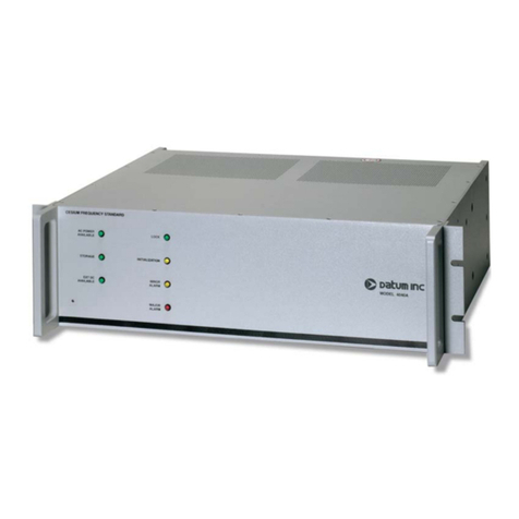
Datum X72 User manual

C/O/106031/I
Designer’s Reference

Datum — Proprietary
Copyright 2000 Datum
All Rights Reserved
Printed in U.S.A.
This material is protected y the copyright and trade
secret laws of the United States and other countries. It
may not e reproduced, distri uted or altered in any
fashion, except in accordance with applica le
agreements, contracts or licensing, without the express
written consent of Datum Irvine.
For permission to reproduce or distri ute please contact:
Pu lications Supervisor, Datum Irvine, 3 Parker,
Irvine, CA 92618-1605.
Ordering Information
The ordering num er of this document is C/O/106031A.
To order this document, call 949 598 7600 and ask for the
Datum Irvine Sales Department.
Notice
Every effort was made to ensure that the information in
this document was complete and accurate at the time
of printing. However, the information presented here is
su ject to change.
Applica le Patents
This product is protected under the following U.S. patent
num ers: 5,457,430, 5,489,821, and patents pending.
Trademarks
X72 is a registered trademark of Datum.
Other trademarked terms may appear in this document
as well. They are marked on first usage.
Warranty
Datum provides a 1 year warranty on the electronics and
a 20 year warranty on the ru idium lamp and cell of this
product.

Table of Contents
SECTION ONE - About This Document
SECTION TWO - Introduction
1.0 Description ........................................................................................... 3
1.1 Typical Applications ........................................................................................ 3
SECTION THREE - Design Integration Considerations
3.1 Mechanical Considerations.......................................................................................... 9
3.1.1 Recommended Mating Connectors .............................................................. 9
3.1.2 Mounting Recommendations........................................................................ 9
3.1.3 Integrating the X72 into a System .............................................................. 10
3.1.3.1 Edge Boards .................................................................... 10
3.1.3.2 Standard Edge Board ...................................................... 11
3.1.3.3 The Anchored Edge Board.............................................. 12
3.1.3.4 3.25 Inch - Connector ..................................................... 13
3.1.3.5 X72 - LPRO Adapter ...................................................... 14
3.2 Thermal Considerations ......................................................................................... 15
3.2.1 Use of Thermal Tape .................................................................................. 15
3.2.2 Frequency offset from Water Condensation in Excess Humidity............... 15
3.2.3 Effect of Excessive Dust............................................................................. 15
3.3 External Interfaces and Grounding............................................................................ 16
3.4 Electrical Interface ......................................................................................... 16
3.4.1 X72 rf Output ......................................................................................... 16
3.4.1.1 RF Output Impedance Versus Frequency ....................... 16
3.4.1.2 AC-coupled rf Load ........................................................ 16
3.4.1.3 Transformer-coupled rf Load .......................................... 17
3.4.3 X72 1 PPS Input and Output ....................................................................... 17
3.4.4 Service Signal .......................................................................................... 17
3.4.5 X72 Frequency Control Signal ................................................................... 18
3.4.6 X72 ACMOS Output Frequency ................................................................ 18
3.5 Frequency Control Analog ........................................................................................ 18
3.5.1 Greater than ±1E-9 Internal or External Control ........................... 18
3.5.2 Time Response of Ext. Frequency Control .................................... 18
3.5.3 Temperature Compensation of Freq. using Ext. Freq. Control ...... 18
3.6 Modifiable Unit Settings .......................................................................................... 20
3.6.1 Hardware Selectable Items ......................................................................... 20
3.6.2 Software Selectable items........................................................................... 20
3.6.3 Temperature Compensation of Frequency Using Ext. C-field Control ...... 20
3.7 EMI Considerations .......................................................................................... 21
3.8 X72 Susceptibility to Input Noise ............................................................................. 21
3.9 X72 Reliability and Maintenance .............................................................................. 22
3.9.1 Reliability .......................................................................................... 22
i

Table of Contents (continued)
SECTION FOUR - X72 Operation
4.1 X72 Installation ......................................................................................... 23
4.1.1 Site Selection ................................................................................. 23
4.1.2 Turn-on Procedure ......................................................................... 23
4.2 Start-up Sequence ......................................................................................... 24
4.3 Theory of Operation ...................................................................................... 25
4.4 Troubleshooting ......................................................................................... 26
4.5 Maintenance ......................................................................................... 27
4.4.1 Repairs ......................................................................................... 27
4.5.2 Warranty ......................................................................................... 28
APPENDIXA
X72 J1 Connector and Plug ............................................................................................................ A1-3
APPENDIX B
Using the Datum Serial Interface Protocol ................................................................................... B1-10
APPENDIX C
Using the X72 Developer's Kit ..................................................................................................... C1-14
ii

1
X72 Rubidium Oscillator
X72 Designer’s Reference 09-20-2001
C/O/106031G
1
Purpose 1
This documen provides basic recommenda ions for designing produc s o use Da um’s X72 ru-
bidium oscilla or. These guidelines are in ended o be generic, as specific produc requiremen s will
vary from applica ion o applica ion.
Technical Support and Warranty Coverage 1
Warran y and non-warran y repair suppor for he X72 is provided by Da um Irvine’s Cus omer
Suppor group. Designer echnical suppor is provided by applica ion engineering from he Irvine
facili y’s Marke ing depar men during he design process.
Scope1
This ma erial consis s of a brief descrip ion of X72 design suppor ed by block diagrams, descrip ion
of environmen al issues, ins alla ion guidelines, required ma ing connec ors, and uni opera ion. This
documen is available in bo h a hardcopy and in Adobe Acroba Reader (.pdf) elec ronic forma .
Intended Audience
This documen is in ended for engineers and elecommunica ions professionals who are designing,
ins alling, opera ing or main aining ime, frequency, and synchroniza ion sys ems having a require-
men for a low profile and highly precise frequency genera or.
Prerequisite Skills and Knowledge 1
To use his documen effec ively, he user should have a good unders anding of digi al elecommuni-
ca ions echnologies and analog frequency genera ion and syn hesis echniques.
Section - About This Document

2
X72 Rubidium Oscillator
X72 Designer’s Reference 09-20-2001
C/O/106031G
How to Use This Document 1
This documen consis s of Sec ions 1 hrough 4, and Appendice A, B and C.
This documen is organized as follows:
• Section : About this Document
Provides general informa ion abou his documen , he in ended audience,
organiza ion and con en s.
• Section 2: X72 Introduction and Overview
This sec ion con ains a descrip ion of he X72 and lis s i s ypical applica ions.
Dimensions, performance and connec or pinou s are documen ed.
• Section 3: X72 Design Integration Considerations
This sec ion con ains mechnical issues per aining o X72 moun ing and
ma ing recommenda ions, including hermal and EMI considera ions, ex ernal
in erfaces and grounding, frequency con rol, suscep ibili y o noise, and
reliabili y goal.
• Section 4: X72 Installation and Operation
This sec ion con ains he informa ion necessary o properly ins all and opera e
he X72 uni including a simplified heory of opera ion, and main enance and
warran y.
• Appendix A: X72 J Connector and Plug
This appendix iden ifies he Molex J1 connec or and i s ma ing plug,
and provides pinou informa ion for he X72 edge board, and 3.25” cable.
• Appendix B: Using the Datum Serial Interface Protocol
This appendix describes use of he ex ernal communica ions link sof ware.
• Appendix C: Using the X72 Deverloper’s Kit
This appendix describes he X72 developer’s ki hardware.

3
X72 Rubidum Oscillator
X72 Designer's Reference 09-08-2001
C/O/106031G
Section 2 - Introduction
2.0 Description
The X72 rubidium oscilla or is he newes and
smalles of DATUM’s family of precision frequency
genera or componen s. This fif h genera ion Rb
oscilla or reflec s significan advances in physics
minia uriza ion and in egra ion and offers a low
heigh (0.70" / 17.7 mm), a small foo prin , and an
indus rial empera ure range of -40˚C o +85˚C.
Drawing on over 30 years of experience, he
X72 design has been refined for low cos mass
produc ion and can be easily in egra ed in o ime,
frequency and synchroniza ion sys ems, requiring
only one inpu supply vol age. I can be moun ed
direc ly on o a circui board as a componen of a
module used in 0.8" wide card slo s. I offers he
high reliabili y and accuracy of a rubidium
oscilla or, in a new design concep benefi ing from
he many years of experience Da um has gained in
fielding ens of housands of rubidium oscilla ors.
2. Typical Applications
The eleva ed opera ing empera ure range of he
X72 se s a new high-poin for his ype of a omic
reference. Compared wi h radi ional quar z oscil-
la ors, he s abili y of he X72 main ains excellen
frequency con rol even when he opera ing em-
pera ure is pushed above 85˚C, so ha even if he
hos sys em overhea s in faul mode, he X72
oscilla or will con inue o produce a s able and
accura e ime or frequency reference.
The X72 is easily in egra ed in o ime and fre-
quency sys ems because of i s low profile. The
heigh and foo prin are designed o accommoda e
0.8" (4I) wide card slo applica ion. The uni oper-
a es wi h a low power requiremen (+5 Vdc or
be ween +10 o 32 Vdc). The X72 mee s all appli-
cable CE and FCC requiremen s for EMI emis-
sions and suscep ibili y.
This design is being successfully applied as an
OEM componen in wireless elecom ne works
such as digi al cellular/PCS bases a ions, SONET/
SDH digi al ne work iming, e c. Linked wi h a
GPS receiver or o her ex ernal iming reference,
he X72 provides he necessary iming require-
men s for CDMA cellular and PCS sys ems. The
low empera ure coefficien and excellen frequency
s abili y ex end holdover performance when he
GPS signal is no available. Tempera ure compen-
sa ed uni s are available for hose special applica-
ions requiring even be er empera ure perfor-
mance.
The X72's 20 year s abili y wi hou he need for
re uning permi s ex ended opera ing periods wi h-
ou main enance (long life Rb lamp, ex ended
crys al con rol range). The design produces a
s able frequency wi h good shor and long erm
s abili y, and excellen spur performance.
Figure 2- . X72 Rb Oscilla or a op an 80's vin age
FRK Rb oscilla or showing he drama ic
reduc ion in size of Rb oscilla or design.

4
X72 Rubidum Oscillator
X72 Designer's Reference 09-08-2001
C/O/106031G
Figure 2-2. X72 Rubidium oscilla or simplified block diagram
Lamp
Energizer Lamp
Heater C-Field
Control
Status
Serial
XO
out
1 PPS IN
1 PPS OUT
f
TTL
f
SINE
Analog
Control
Cell
Heater
Microwave
Generator
Filter/
Amp
X
n
XO
Mod Synth
DATUM Proprietary
Digital Control Kernel
DC / DC
Converter
and
filters
+5 Vdc
or
10 - 32 Vdc
Conditioned
Voltages
X72 Block Diagram
EF 1/19/00
Da um's commi men o quali y and reliabili y
is backed by a 20 year warran y on he physics
package (lamp bulb and resona or cell).
The microprocessor-based X72 is a more cos -
effec ive sys em design ha allows serial com-
mand selec ion and enabling of TTL level digi al
ou pu frequencies. This allows he oscilla or ou -
pu o be divided o a number of differen frequen-
cies, as opposed o older oscilla ors wi h a single
fixed ou pu frequency. The sine ou pu frequency
is selec ed a ime of order.
A 1 PPS ou pu is an in egral par of he design.
An op ional 1 PPS inpu allows he uni o rack a
GPS or o her ex ernal reference, and display he
difference be ween he inpu and he 1 PPS gener-
a ed by he X72 hrough he RS232 link.
For simple applica ions he X72 provides a 5V
CMOS-compa ible Buil -in Self Tes (BIST)
Service and a LOCK alarm signal derived from he
basic physics opera ion. This lock signal indica es
when he ou pu frequency is locked o he a omic
resonance of rubidium. When more con rol over
he device is desired, an ex ensive command -
con rol - s a us dialog is available.
In addi ion o con rolling he opera ion of he
oscilla or, he microprocessor's buil -in firmware
allows an ex ernal hos compu er o communica e
wi h he embedded con roller hrough a serial por
connec ion. This allows precise frequency con rol,
he dynamic frequency selec ion men ioned earlier,
he abili y o enable and disable ou pu s, o query
he sys em's heal h, and acquire informa ion abou
he uni 's serial number, opera ing empera ure,
faul his ory, ini ia e a self es , and o her
performance indica ors. The pro ocol used is
Da um's proprie ary Da um Serial In erface
Pro ocol, or DSIP.
The simplified block diagram below shows he
impor ance of he digi al con rol in he uni , how i
con rols and moni ors all aspec s of opera ion, such
as he hea er circui s of he physics package, as well
as he selec ion of ou pu s.

5
X72 Rubidum Oscillator
X72 Designer's Reference 09-08-2001
C/O/106031G
Bottom View
Front View
Top
Base Plate
3.00
(76)
3.50 (89)
0.70 (18)
2.75
(69.9)
3.250 (82.6)
MOLEX Connector
P/N 52629-2651
Mate with MOLEX
P/N 52660-2651
shown below
CAUTION: unit has an internal fuse
but has no reverse polarity
protection!
NOTE: all pins must be connected!
02
01 26
25
4X M3X.5 X .20 (5.1)
Baseplate
mounting
holes (4)
2.07
(52.5)
0.42 (10.6)
Figure 2-3. Ou line Drawing, X72 uni
Table 2- . J1 Connec or In erface
PIN# SIGNAL NAME TYPE** SIGNAL FUNCTION
1 - 7 VDD PWR +Power inpu (+4.5 o 5 Vdc or +10 o +32 Vdc).
All power pins mus be connec ed.
8 SERVICE Ou pu Indica es uni is nearing limi s of frequency con rol and ha
Service is required wi hin several mon hs.
9 DOUT Ou pu UART da a ou a ACMOS logic levels.
10 DIN Inpu UART da a in a ACMOS logic levels.
11 FREQ CTRL Analog Frequency con rol - analog inpu be ween 0 - 5 Vdc.
12 - 18 VSS GND -Power & signal re urn - all grounds mus be connec ed.
19 1 PPS IN Inpu 1 PPS inpu , posi ive edge riggered.
20 1 PPS OUT Ou pu 1 PPS ou pu , may be enabled/disabled digi ally.
21 LOCK Ou pu If low, indica es Rb osc. is locked.
22 FXO Ou pu * (FXO) ACMOS ou pu equalling he VCXO frequency.
23 FACMOS RTN GND Re urn for FACMOS & FXO signals.
24 FACMOS OUT Ou pu (FACMOS) ACMOS ou pu equalling VCXO frequency.
25 FSINE RTN GND Chassis ground - re urn signal for FSINE signal.
26 FSINE OUT Ou pu (FSINE) Sine ou pu op ion - equals VCXO frequency
divided by 2xM (M is se a he fac ory).
* High impedance ** All inpu s and ou pu s are ESD pro ec ed, shor circui pro ec ed,
and all inpu s are compa ible wi h 3.3V ACMOS logic and 5V TTL logic.
NOTE: Refer o Appendix A for he connec or manufac urer's drawings and specifica ions.

6
X72 Rubidum Oscillator
X72 Designer's Reference 09-08-2001
C/O/106031G
Table 1: ABSOLUTE MAXIMUM RATINGS
Symb CHARACTERISTIC -40 Degrees C UNITS
ol (Uni in ambien s ill air - o 85 C
Symbol CHARACTERISTIC -40 Degrees C to 85 C UNITS
(Unit in ambient still air – convection) Base-plate
VCC SUPPLY RELATIVE 5 VOLT UNIT -0.25 to 8 V
10 TO 32 VOLT UNIT -0.25 to 40
VIN DIN & 1PPSIN -0.5 to 5.5 V
FREQ CNTL -0.5 to 5.5
PWU MAX WARM UP POWER 17 WATTS
PQ MAX QUIESCENT POWER -40˚C BASEPLATE 15 WATTS
25˚C BASEPLATE 10
85˚C BASEPLATE 5.0
twu MAXIMUM WARMUP TIME -40˚C BASEPLATE <8 MINUTES
25˚C BASEPLATE <4
TMOBP Conditions: Still Air – -45 to 85 ˚C
TMTBP Conditions: Still Air – -40 to 85 ˚C
TSTG MAXIMUM STORAGE TEMPERATURE -55 to 85 ˚C
MAXIMUM VIBRATION Sine – 1 inch DA or 10G 0 to 300 Hz
MAXIMUM VIBRATION Sine – 1 inch DA or 10G 0 to 100 Hz
MAXIMUM ALTITUDE With respect to Sea Level 30,000 Feet
MAXIMUM ALTITUDE With respect to Sea Level 50,000 Feet
NOTE: ALL OUTPUTS ARE SHORT CIRCUIT PROTECTED
INPUT VOLTAGE
RELATIVE TO GND
REGARDLESS OF POWER
SUPPLY VOLTAGE
Lock to < 1E-9
Lock to < 1E-9
MAXIMUM ABSOLUTE
TURN-ON BASEPLATE
TEMPERATURE
MAXIMUM ABSOLUTE
OPERATING BASEPLATE
TEMPERATURE Convection – No Heat
Sink on Unit
Convection – No Heat
Sink on Unit
(Powered but
not locked)
(Powered and
maintaining lock)
(Powered up unit)
(Unpowered)
TO GROUND
TABLE 2-2. X72 Design Absolu e Maximum Ra ings

7
X72 Rubidum Oscillator
X72 Designer's Reference 09-08-2001
C/O/106031G
TABLE 2-3. X72 Design Opera ing Charac eris ics
Symbol CHARACTERISTIC -40 Degrees C to 85 C UNITS
(Unit in ambient still air - convection) Base-plate
MIN TYP
MAX
DIGITAL INPUTS/OUTPUTS
V
CC
SUPPLY RELATIVE 5 VOLT UNIT 4.5 5.5 V
TO GROUND
10 TO 32 VOLT UNIT 10 32
V
IH
HIGH LEVEL INPUT DIN 2.5 5.5 V
VOLTAGE
1PPSIN 1.8 5.5
V
IL
LOW LEVEL INPUT DIN 0 0.8 V
VOLTAGE
1PPSIN 0 0.8
V
OH
HIGH LEVEL OUTPUT DOUT, SERVICE, 3.3 V
VOLTAGE LOCK
@IOH = -0.33 mA
@ IOH = 0 mA
FXO, FACMOS, 3.5
1PPSOUT
@IOH = -3.5mA
V
OL
LOW LEVEL OUTPUT DOUT, SERVICE, 0.4 V
VOLTAGE LOCK
@IOL = 0.1 mA
FXO, FACMOS, 0.4
1PPSOUT
@IOL = 1.7 Ma
ANALOG INPUTS/OUTPUTS
V
FC
FREQUENCY CONTROL RANGE OF ±1.5E-9 5 V
INPUT VOLTAGE RANGE WITH RESOLUTION OF
2.0E-12
P
SO
FSINE OUTPUT FACTORY SET with 7.0 8.6 dBm
POWER RANGE (Output load of
390pF cap & 50 Ω
resistor within 4
inches of FSINE pin).
FREQUENCY CONTROL
∆F/F
R
CONTROL RANGE ANALOG (FREQ CTRL PIN) -1.5E-9 +1.5 ∆Hz/Hz
DIGITAL INTERFACE -1.0E-6 +1.0E-6
∆F/F
RES
FREQUENCY CONTROL RESOLUTION 2.04 E ∆Hz/Hz
-12

8
X72 Rubidum Oscillator
X72 Designer's Reference 09-08-2001
C/O/106031G
Figure 2-5. To al X72 Quiesen Power Dissipa ion, Typical (free convec ion)
Figure 2-6. Represen a ive X.72 ∆f/f versus Tempera ure (uncompensa ed)
Basepla e Tempera ure (deg C)
To be added when available
5 V, 10 - 32 V
-40 -30 -20 -10 0 25
BASEPLATE TEMPERATURE [˚C]
10 20 30 40 50 60 70 80 85
0
5
10
15
POWER DISSIPATION [WATTS]
20
Refer o he X72 Performance Charac eris ics documen for more de ailed informa ion.

X72 Rubidium Oscillator
9
X72 Designer’s Reference 05-31-2002
C/O/106031I
3.1 Mechanical Considerations
3.1.1 Mounting Recommendations
The X72 may be mounted to a circuit card or chassis using the four mounting holes located at the
corners of its baseplate. An interface cable or adapter card is required to access the X72 outputs and
to interface with a host system.
Four M3 stainless steel screws with a minimum penetration depth of .2" and a maximum of .5” can
be used to mount the unit.
3.1.2 Recommended Mating Connectors
Shielded cable must be used between the X72 connector and the host system connector in order to
meet noise and emissions requirements noted in the engineering specifications of the X72 product. It
is recommend that for typical applications this interface cable be no longer than 4 inches (10 cm).
Section 3 - Design Integration Considerations
X72 Unit
Interface Options (edge adapter cards or cables)
X72 Unit
(drawing not to scale)
Side View
Top View
Test Interface Cable
(2 X 8 Pin Header Strip - farside)
3' P/N 060032-001
3.25" P/N 060031-001 Interface cable
2 X 13 Pin
Header Strip
*
Insert filter capacitor:
10 MHz / 390 pf NPO 5%
13 MHz / 330 pf NPO 5%
15 MHz / 270 pf NPO 5%
Anchored
Edge Board
Standard
Edge Board
3.25"
Connector
P/N 106031-XXX
P/N 106569-002
P/N 106569-003
Unpopulated
Edge Board
P/N 106568-001
*
LPRO Adapter
2 X 8 hole
connector area
LPRO
Filter
Connector
(farside)
P/N 106734-001
Filter
connector
(provides filter
capacitor)
Figure 3-1. Adapter cards, cables and cable options

X72 Rubidium Oscillator
10
X72 Designer’s Reference 11-09-2001
C/O/106031H
3. .3 Integrating the X72 into a System
Da um has developed several in egra ion op ions o aid he sys em designer in in egra ing he X72
in o heir applica ion. Wi h hese op ions here is almos no limi o he connec ion schemes pos-
sible. Each of hese op ions are described below.
3. .3. Unpopulated Edge Board
The Unpopula ed Edge Board is a small prin ed circui board (PCB) ha plugs direc ly in o he
X72’s Molex connec or.
The Unpopula ed Edge Board includes unpopulated pads for he following componen s
1. 16-pin header (See pin ou comparison in Appendix A)
2. Coaxial connec or for he Sine Ou pu
3. Resis or and Capaci or pads o allow for improved Sine Ou pu dc fil ering
(See Capaci or no e)
From he various in erface poin s on he Edge Board a sys em designer can access all inpu s and
ou pu s of he X72 and can moun which ever connec ors are necessary for heir applica ion. This
opens he X72 up o nearly any connec ion scheme. The examples included in his documen are jus
a few of he in egra ion me hods possible wi h hese edge boards.
The Edge Board comes in hree differen versions: Unpopula ed (PN 106568-001), S andard (PN
106569-003), and Anchored (PN 106569-002). The hree versions are elec rically iden ical. They
differ in ha he Anchored version is 3.5 inches long (S andard version is 1.74 inches long) and
includes wo anchor poin s (refer o Figure 1.6). In addi ion, he s andard edge board includes he
header ha is moun ed direc ly o he PCB by direc solder connec ion or by plugging in o a socke
provided by he user.
Refer o Figure A-3 in Appendix A for a schema ic of he connec or pinou s.
Unpopulated
Edge Board
P/N 106568-001
*
*Insert filter capacitor:
10 MHz / 390 pf NPO 5%
13 MHz / 330 pf NPO 5%
15 MHz / 270 pf NPO 5%

X72 Rubidium Oscillator
11
X72 Designer’s Reference 11-09-2001
C/O/106031H
(2 X 8 Pin Header
Strip - farside)
Standard
Edge Board
P/N 106569-003
3. .3.2 Standard Edge Board - PN 06569-003
The S andard version is in ended for implemen a ions where he Edge Board is connec ed direc ly
in o he sys em board by soldering direc ly o he PCB or plugging in o a socke provided by he user
(see example below). The Edge Board achieves i s mechanical s abili y from he direc connec ion.
The Standard Edge Board includes:
1. 390 pf capacitor
2. 10 Ohm resistor
3. 15 µF capacitor
4. Pad for coaxial connector
for sine output
5. Soldered 2 X 8 pin connector
adapter for connection to PCB
Example of
mounting

X72 Rubidium Oscillator
12
X72 Designer’s Reference 11-09-2001
C/O/106031H
3. .3.3 The Anchored Edge Board - PN 06569-002
The Anchored Edge Board can be used in applica ions where he Edge Board is no plugged in o a
PCB and does no have a solid elec rica1 connec ion like a soldered header ha can keep he Edge
Board in place in harsh vibra ion environmen s. To accomoda e hese applica ions wo anchor
poin s are provided.
Anchored
Edge Board
P/N 106569-002
The Anchored Edge Board includes:
1. 390 pf capacitor
2. 10 Ohm resistor
3. 15 µF capacitor
4. Pad for coaxial connector
for sine output
5. Unpopulated 16 pin header strip
for customer integration.
Example of
mounting

X72 Rubidium Oscillator
13
X72 Designer’s Reference 05-31-2002
C/O/106031I
3.1.3.4 3.25 - Connector - PN 060031-001
The 3.25 inch connector h s been discontinued s bo rd connection option for the X72.

X72 Rubidium Oscillator
14
X72 Designer’s Reference 11-09-2001
C/O/106031H
3. .3.5 X72 - LPRO Adapter - PN 06734-00
The X72-LPRO Adap er was developed for exis ing Da um LPRO cus omers. The Da um LPRO
Low-Profile Rubidium Oscilla or, is he mos widely produced rubidium oscilla or in he world, and
has been designed in o hundreds of applica ions. The X72-LPRO Adap er allow hese cus omers o
upgrade o he X72 wi hou changing he physical in erface in heir uni .
The S andard Edge Board and he LPRO Compa ible Op ion Board bo h have socke s. The pins of a
2 X 8 pin connec or are soldered be ween hese wo boards. The LPRO fil er connec or does no
require he ins alla ion of a fil er capaci or, since i was designed o provide a fil ering func ion.
2 X 8 hole
connector area
2 X 8 hole
connector area
2 X 8 pin
connector
adapter
LPRO
Filter
Connector
(farside)
X72, Standard Edge Board,
and LPRO Connector
(side view)
Standard
Edge Board
LPRO
Compatible Option
P/N 106569-003
P/N 106734-001
*
Filter
connector
(provides filter
capacitor)
X72

X72 Rubidium Oscillator
15
X72 Designer’s Reference 11-09-2001
C/O/106031H
3.2 Thermal Considerations
3.2.1 Use of Thermal Tape
In order to achieve the highest ambient operating temperature for the X72 operating baseplate
temperature it is recommended that the bottom (“baseplate”) of the X72 have good thermal contact
to the mounting surface. It is also very important to maintain a uniform temperature into the base-
plate of the X72 through its mounting points. The X72 unit will operate normally without use of
thermal tape, but for some field applications the tape may simplify customer system thermal design
requirements.
WARNING: Unless attached to a surface to spread its heat the X72 will be HOT
to the touch and may cause handling distress.
The X72 maximum baseplate temperature described in the specifications was based on a
model where the unit was covered on five sides with one inch foam to simulate free convection in air
as the heat sink/baseplate was exposed to forced air.
If there is air flow over the unit's top cover, the X72's maximum operating baseplate tempera-
ture will increase by 1 or 2 degrees C and its power consumption at a given baseplate temperature
will also increase by a few tens of milliwatts.
As the baseplate temperature continues to increase the unit will eventually lose lock. Above a
baseplate temperature of +85˚C the resonator or lamp heaters shut down as control point tempera-
tures are exceeded and the unit temperaåure coefficients increase to approximately 6E-10/˚C.
3.2.2 Frequency Offset from Water Condensation during Times of Excessive Humidity
Condensation of moisture from the air onto electrical components will produce frequency spikes or
instability until the heat of the operating unit drives out the water vapor.
Condensation will not cause a problem for environments meeting the X72 specification if the
X72 baseplate thermal ramp rates are controlled so that they rise at less than 2˚C/minute.
3.2.3 Effect of Excessive Dust on the X72
Operating the unit in dusty conditions may cause unexpected thermal effects if it builds up on the top
surface. Excessive dust will also contribute to contamination in the shell of the mating connector and
could cause intermittent loss of signals.
The X72 is shipped in a dust-protected ESD resistant bag. All connectors on any product must be
suitably protected, before mating, in a dust-controlled environment.

X72 Rubidium Oscillator
16
X72 Designer’s Reference 11-09-2001
C/O/106031H
3.3 External Interfaces and Grounding
Figure 3-1 shows interface circuitry for J1, the X72 I/O connector. All signals, including power,
power return, rf output, signal/chassis ground, and monitor lines are routed through this connector.
All voltage supply and ground lines must be connected at the mating connector for the X72 unit to
operate properly.
The X72 is constructed with the chassis (unit cover) and signal grounds tied together at
multiple points, and with the power supply return isolated from both chassis and signal grounds only
by a ferrite bead. This robust grounding approach allows for ESD protection and low spurious
emissions. But it can also lead to ground loop issues for the user.
Workarounds commonly used to break dc ground loops at a higher level of integration are to use a rf
isolation transformer for the sine rf output, and/or float the transformer secondary winding of the
user's power supply.
3.4 ELECTRICAL INTERFACE
3.4.1 X72 rf Outputs
3.4.1.1 RF Output Impedance versus Frequency
The active rf output impedance for X72 is a nominal 50 ohms at 10 MHz, but is a widely varying
impedance at other frequencies. This would have to be taken into consideration if the X72 rf output
is driving a non-buffered filter. Note that X72 is specified as delivering 0.55V ±10% into a 50 Ohm
resistance load. Loads that present complex impedance or resonances will affect signal amplitude.
X72 can drive a properly terminated transmission line of 50 Ohms characteristic impedance.
NOTE: a 390 pf capacitor from the 10 MHz sine output to the sine return is required
within 4 inches of the output connector. It can be located across the
50 ohm terminator (see Figure 3-1).
If the sine output port is disabled its characteristic impedance remains the same.
3.4.1.2 AC-Coupled rf Load
The X72 is designed to tolerate an ac-coupled rf load without waveform distortion provided the
coupling capacitor is low impedance at 10 MHz (for example, a 0.01 uF capacitor has an Xcof 1.6
ohms, which is small compared to the fifty ohm nominal output impedance). The rf output stage of
the X72 uses an ac-coupled design.
It is recommended that the coupling capacitor be ceramic, with a X7R or NPO dielectric.
Table of contents
Other Datum Measuring Instrument manuals
Popular Measuring Instrument manuals by other brands
Thermo Scientific
Thermo Scientific Orion Star A113 instruction sheet
Mitsubishi Electric
Mitsubishi Electric EcoMonitorPro EMU2-RD3-F instruction manual
ETS-Lindgren
ETS-Lindgren 5225 Series manual
Apator
Apator ELF Technical description
EUTECH INSTRUMENTS
EUTECH INSTRUMENTS NITRATE EPOXY instruction manual

Sensaphone
Sensaphone SAT4D user manual
