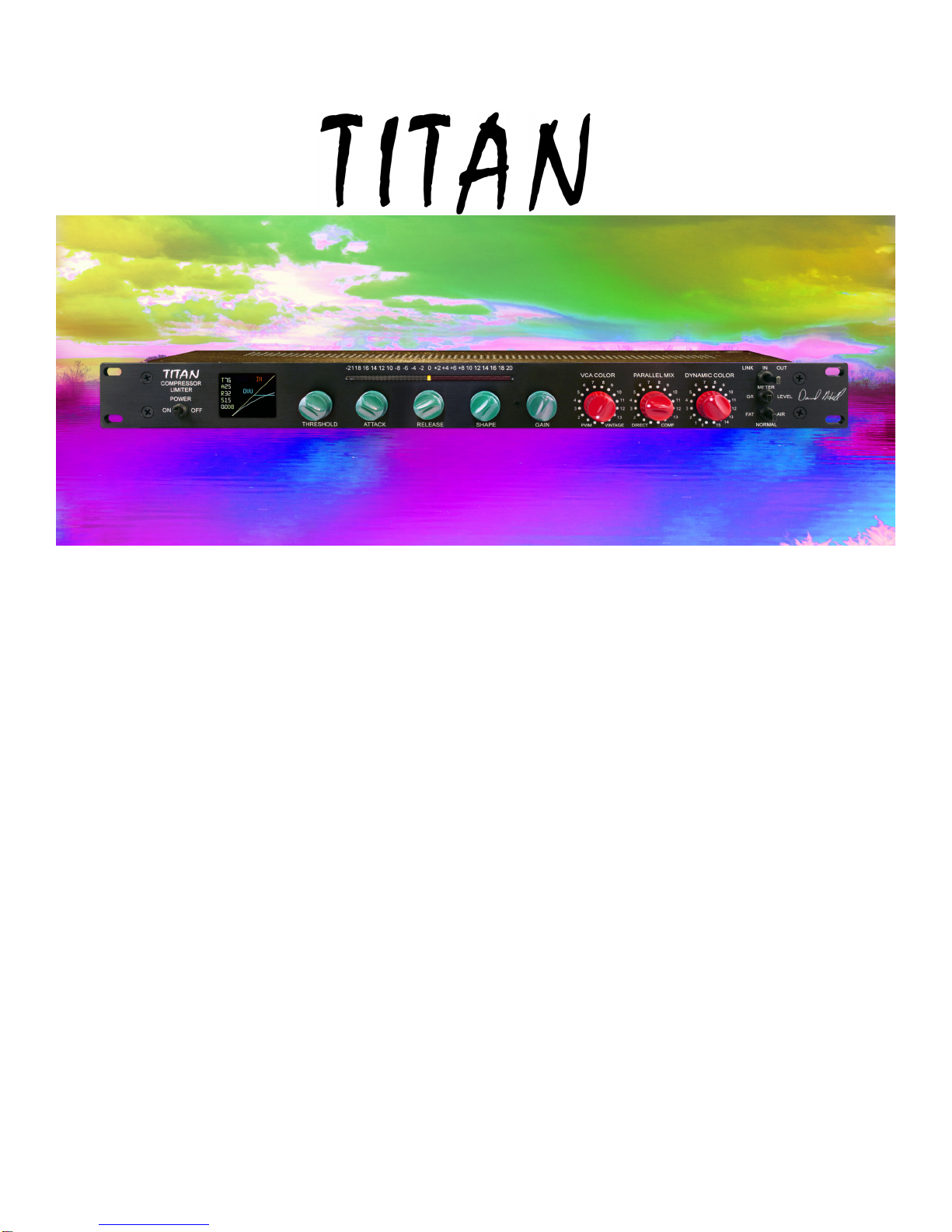
Dave Hill Designs TITAN Installation guide
© 2012 Dave Hill Designs
COMPRESSOR LIMITER
MANUAL VER 1.2
201200219
2117 E5th street
Superior WI USA
54880
davehilldesigns.com
See the next page for startup switch settings
Start Up Settings 2
Safety Information 3
Introduction - The Controls 4
LCD Reference 7
Panel Guide (control range) 8
Specifications 9
SETTINGS TO START WITH
BYPASS
SET TO IN
FAT - AIR
SET TO AIR
COMPRESSOR
COLOR
(VCA COLOR)
SET TO PWM
PARALLEL MIX
SET TO COMP
DYNAMIC
COLOR
SET TO 0
MAKE UP GAIN
SET TO 0
STANDARD CONTROLS
SET TO 45 30 30
POWER
SET TO ON
THRESHOLD
SET AS NEEDED

IMPORTANT SAFETY INSTRUCTIONS
1. Read these instructions
2. Keep these instructions
3. Heed all warnings
4. Follow all instructions including Calibration Instructions
5. Do not use this apparatus near water
6. Clean only with dry cloth
7. Do not block any ventilation openings. Install in accordance with the manufacturer’s instructions
8. Do not install near any heat sources such as radiators, heat registers, stoves, or other apparatus
(including amplifiers) that produce heat
9. Protect the power cord from being walked on or pinched particularly at plugs and the point where
they exit from the apparatus
10. Only use attachments/accessories specified by the manufacturer
11. Unplug this apparatus during lightning storms or when unused for long periods of time
12. Refer all servicing to qualified service personnel. Servicing is required when the apparatus has
been damaged in any way, such as power-supply cord or plug is damaged, liquid has been spilled
or objects have fallen into the apparatus, the apparatus has been exposed to rain or moisture,
does not operate normally, or has been dropped
13. CAUTION: To disconnect the unit completely from the MAINS, unplug the unit. Turning the power
switch off does not disconnect the unit completely from the MAINS.
14. Unit must be operated with a minimum distance of 18” from any object
15. The unit shall not be exposed to dripping or splashing and that no objects filled with liquids, such
as vases, shall be placed on the unit.
16. THIS EQUIPMENT MUST BE USED IN ASTANDARD RACKMOUNT CONFIGURATION. DO
NOT USEAS A DESKTOP OR MOUNTED ON OR BELOWANY OTHER EQUIPMENT.
CHECK THE LINE VOLTAGE SETTING BEFORE PLUGGING THE UNIT IN

INTRODUCTION
Titian is an analog compressor-limiter with a very large range of color and control choices that has
reset-ability. The main audio path is digitally controlled analog with discrete class A electronics. The
side chain is built with a very high speed dsp that allows the design to push the limits beyond what is
possible in the design of an analog side chain. Reset-ability is attained by using stepped controls and
encoders that have their values displayed on Titian’s color LCD display or are indicated by markings
on the front panel. The LCD display also shows the in-out status of the compressor. In the stereo link
mode it shows which device is the master and slave
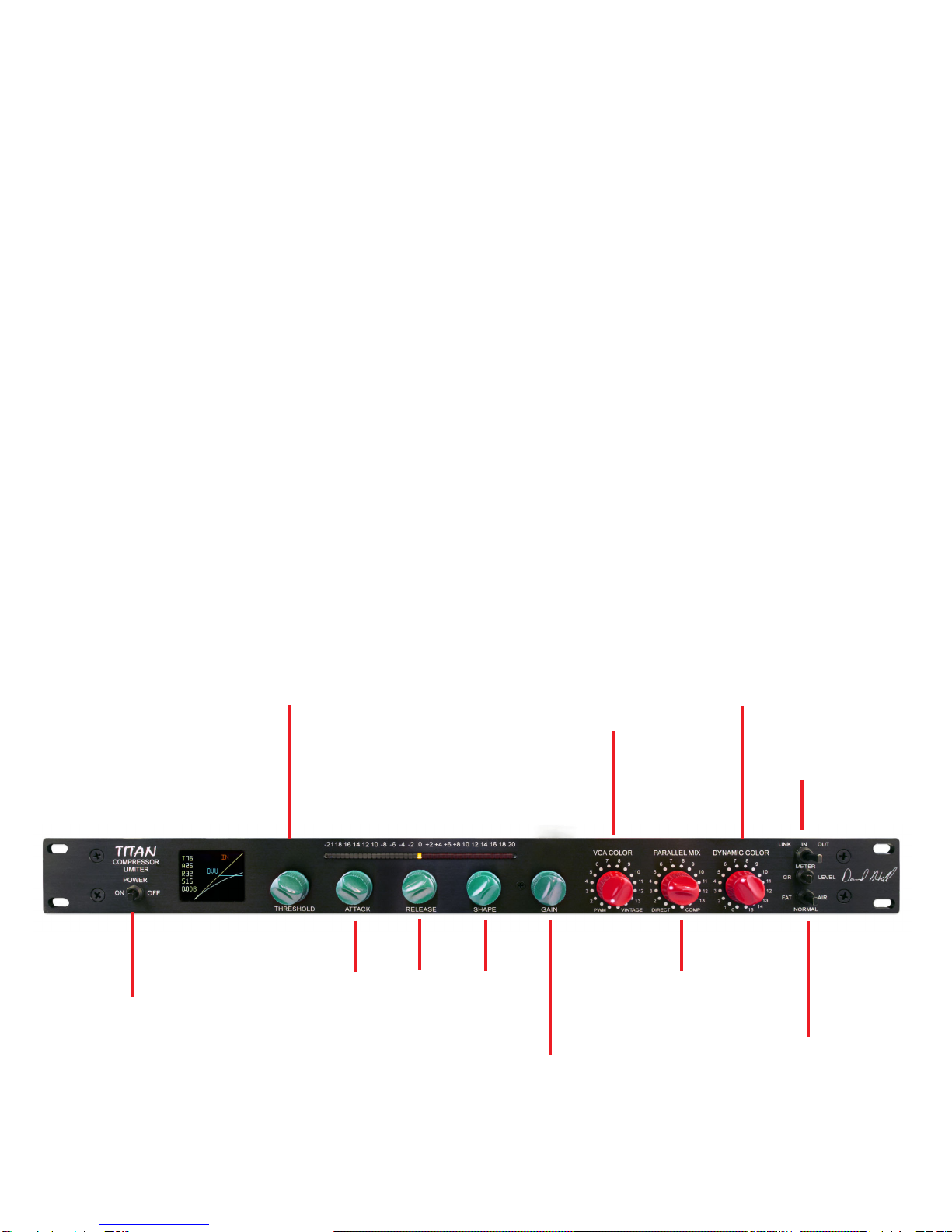
THRESHOLD, ATTACK, RELEASE, AND SHAPE CONTROLS
The values or settings of the controls are displayed on the LCD display. This allows repeatability of
settings. The knee shape is graphically displayed on the LCD and this graph interacts with the
Threshold and Shape controls showing the knee character and thus how the ratio changes. There is
a 0VU = +4dbu reference line and the top of the graph is +25dbu.
The Threshold, Attack, Release, and Shape controls have a range of 0 to 99. This is 100 steps,
being it is a feed back style compressor, control values like attack and release change depending on
the threshold, knee shape and how much gain reduction is taking place. The four controls have a two
speed range that allows you to get from one end of the control setting to the other with a single fast
turn of the control. This gives the control a more pot like behavior when going from one end to the
other. When you turn the control slower is will change the value by increments of 1 to allow fine
adjustment.
COLOR CONTROLS
Titan has a set of controls that allows the user to change the color of the compressor.
This group of controls; the three red knobs and one toggle switch allow the user to do things that are
not available on any other compressor-limiter. The controls do a complete rotation, no end stop. This
makes is easy to do a process full on – process off comparison. The controls have been designed to
help keep any pops to a low level when changing them. When making the full on to full off change it
is possible to create a pop in the audio path, this is the worst case change.
PARALLEL MIX
The PARALLEL MIX control blends the unprocessed audio with the compressed audio, a mixing
function. There are 16 steps in the cross fade-mix control for a wide range in control. The Direct
setting is almost all unprocessed audio. It is somewhere around 6% of the compressor audio and
94% direct audio. For 100% direct use the bypass switch. When using the Parallel Mix control it is
best to level match the make up gain of the compressor with the direct audio path. If there is a large
level mismatch it will increase the step level changes and thus popping when the control is changed.
COMPRESSOR COLOR – (VCA COLOR)
The control provides a mix between a very clean PWM gain control device and a vintage gain control
element. The vintage gain control element is a diode type compressor circuit designed for a high
level of color. There are 16 steps in the cross fade-mix control for a wide range in choices.
DYNAMIC COLOR
The DYNAMIC COLOR control is a control that generates harmonic content that is of opposite phase
as compared to the harmonic content that the vintage gain control element generates. The effect of
the Dynamic Color control can be described as making the sound “bigger”. It can also be thought as
expanding the transits at the same time one is compressing. (Waveform expansion while compressing
the envelope) The dynamic color control will not function with out gain reduction taking place. The
compressor attack and release times will also affect the sound of this control. The DYNAMIC COLOR
control has 16 steps in order to provide a wide range of sonic choices. It is useful in giving
instruments more punch. Try it on kick or snare. Enhance the attack of the individual strings in a
guitar strum or notes in a piano chord. In program material it can put some life back into the source
and make it sparkle a bit. Being it is mostly third harmonic in nature it will also make some material a
bit brighter. When using it, the gain reduction meter will show more leds being lit up this is an
indicator of it working.
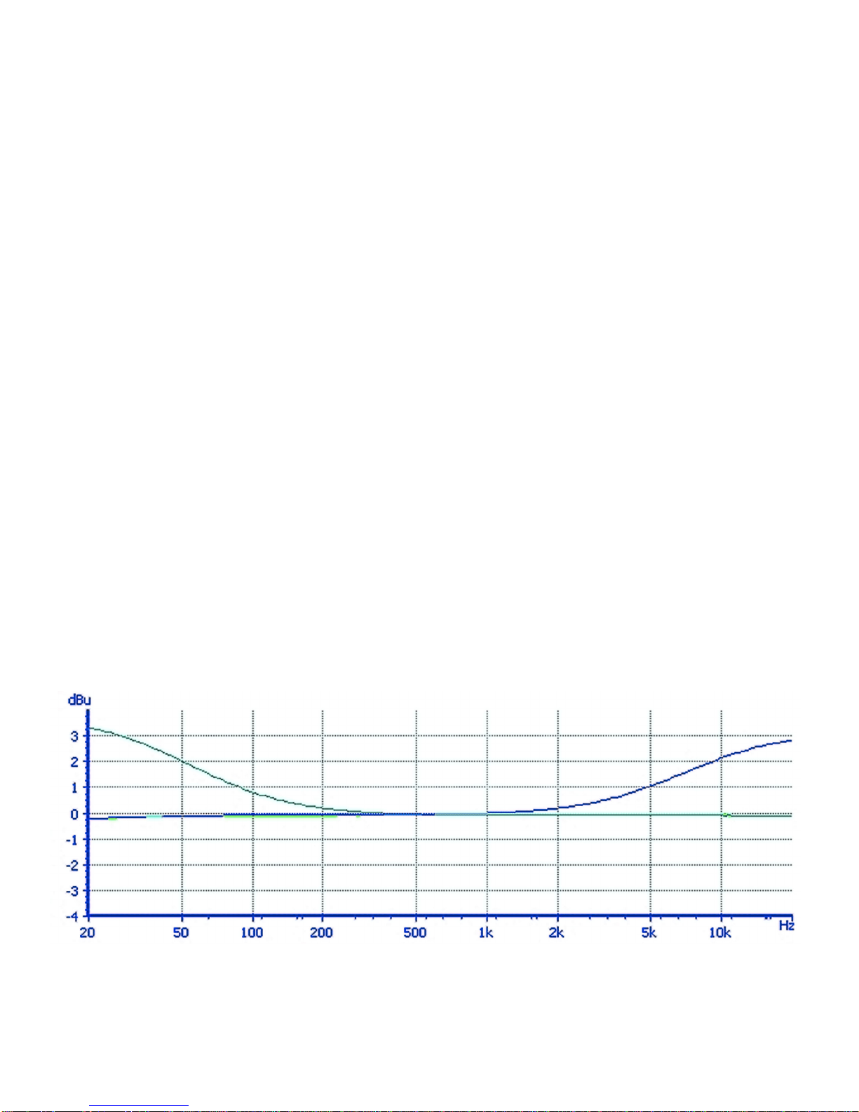
FAT – AIR
The FAT – AIR switch will add fatness or air to the compressed audio. This is by causing the
frequency response of the compressor to change with gain reduction. Air has a high frequency rise
and Fat has a low frequency rise. The compressor attack and release times will also affect the sound
of these settings.
FAT – AIR FREQUENCY RESPONCE REFERENCE GRAPH
This graph showes how the frequency responce changes with the FAT or AIR function on. The
measurement is done is a test mode at 12 db of gain reduction. In operation it is very complex and
beyond what a simple graph can show.

STEREO LINK
When stereo linked the unit selected as the control master will control all functions on the second
channel. The LCD display will show which unit is the control master. When working in stereo all
controls on the slave unit are disabled.
When switched out / bypassed, Titan is hard bypassed by a relay; this relay will also bypass the unit
when power is off.
LINK-IN-BYPASS For the Link - In - Out switch to work correctly in the link mode the unit that is to be
the slave unit should be set to out. With this setting the Link - In - Out switch will work as a master in -
out switch by moving the switch from LINK to OUT on the master unit.
The link function works by sending data commands from the master unit to the slave unit, being the
side chain is a dsp the side chain functions will precisely match. The analog outputs of the detector
circuits are also tied together during link so that each channel sees the same analog control signals.
Power up during link In normal operation everything is fine as long as both units are powered at the
same time. On power up the master unit will see that it is to be the master and will not start
commutation with the slave for a few seconds longer, allowing the slave unit to be powered up first. If
the master unit is very late on power up or both units have master selected, commutation will fail and
the link will not work. To correct this, switch both units to out and then set the master unit to master.
METER SWITCH
The meter switch selects weather the meter in showing gain reduction or level
0VU = +4dbu with +24dbu being the top of the meter
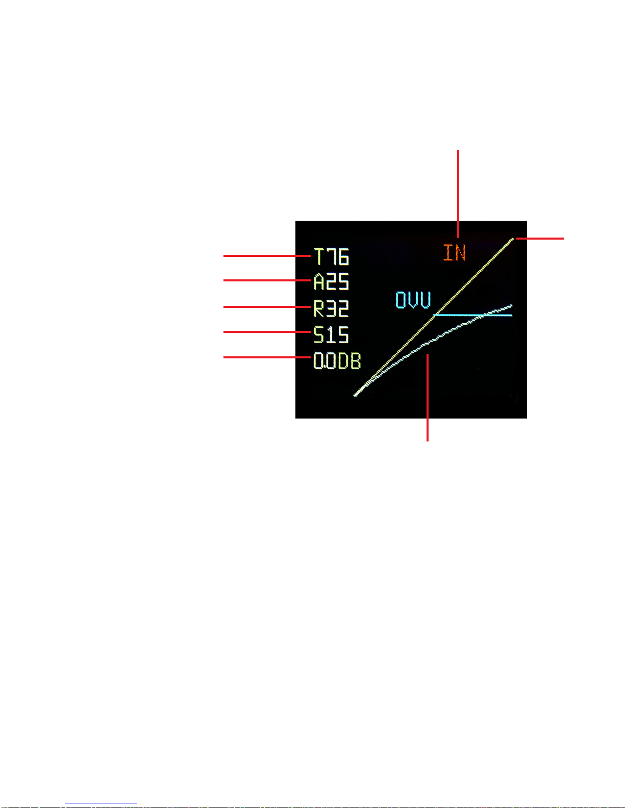
THRESHOLD
ATTACK
RELEASE
KNEE SHAPE
MAKE UP GAIN
IN - OUT - LINK STATUS
KNEE SHAPE GRAPH
TOP
+25DBU
LCD DISPLAY REFERENCE
LCD CLEANING
First use care, the best way to clean it is with camera lens cleaning supplies, a micro fiber cloth, an air
bulb with a brush. Do not use chemicals, do not touch the surface with you fingers. The surface has
a anti glare, anti static coating, chemicals may mess it up.
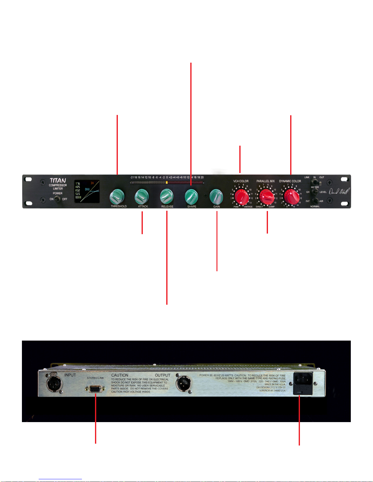
LINE VOLTAGE
SELECTION
LINK CONNECTOR
COMPRESSOR
COLOR
(VCA COLOR)
PWM 0.018% THD
@ +24 dbu
VINTAGE
13% THD @ +24dbu
PARALLEL MIX
DYNAMIC
COLOR
MAKE UP GAIN
0.5db steps
Max Gain = 11.5db
ATTACK TIME
Fast = 50uS
Slow = 400mS
THRESHOLD
RELEASE TIME
Fast = 50mS
Slow = Greater than 5 Seconds
SHAPE of the Knee
Hard ratio =10 to 1
Soft = 1.1 to 1

SPECIFICATIONS
Maximum input: +25dbu balanced
Maximum output: +25dbu balanced
Make Up Gain: 0 to 11.5db, 0.5 steps
Noise: -91dbu, 20 KHz BW
Frequency Response: 3Hz to175KHz
Distortion, clean mode @+25dbu: 0.018%
Power: 25 watts at 115 or 230 volts, 50 or 60 Hz.
Fuse size is slow acting fuze GMD 0.315A for 115 volts; GMD
0.150A for 230 volts
for 100 - 120 volts set to 115V
for 220 - 240 volts set to 230v
Shipping Weight: 15 lbs (6.7kg)
Depth Behind Panel: 8.625 inches plus user input/output connectors
Acknowledgements
There are a number on people who have suggested ideas that have helped Titan evolve into the
controllable device that it is.
They inculude; Jean Hund, Raf Lenssens, Michiel Hollanders, Mathijs Indesteege, Niki Melville-
Rogers, Nick Mitchell, Wes Osborne, Andrew Scheps, Fab and others
Table of contents
Popular Air Compressor manuals by other brands


Makita
Makita MAC8000 user manual

Campbell Hausfeld
Campbell Hausfeld FP204100 Operating instructions and parts manual

York
York Turbomaster M Series Installation, operation and maintenance manual

Craftsman
Craftsman 919.727130 owner's manual

Ohio Medical
Ohio Medical P20-M Operation manual

DeWalt
DeWalt DXCM603 instruction manual


