jobmate 58-7992-0 User manual

8-gallon Air Compressor Kit
58-7992-0
Instruction Manual
For Parts, Service, Warranty or other Assistance, please Call 1-877-888-3872
Manual 58-7992 V 1.7– 8 Gallon compressor
2005-7-19

Table of Contents
Safety Guidelines - Definitions Page 2
Hazard Warnings 3
5.5 HP Air Compressor 7
Precautions 7
Basic Air Compressor Components 8
Assembling the Compressor 8
Compressor Controls 9
Electrical Power Requirements 9
Breaking In The Pump 10
Operating Instructions 11
Maintenance 11
Storage 12
Service 12
Troubleshooting 13-15
Glossary of Terms 15
Limited Warranty 16
Parts list 17-18
WARNING! READ AND UNDERSTAND ALL SAFETY PRECAUTIONS IN
THIS MANUAL BEFORE OPERATING. FAILURE TO COMPLY WITH
INSTRUCTIONS IN THIS MANUAL COULD RESULT IN PERSONAL INJURY,
PROPERTY DAMAGE, AND/ OR VOIDING OF YOUR WARRANTY. JOBMATE
WILL NOT BE LIABLE FOR ANY DAMAGE BECAUSE OF FAILURE TO FOLLOW
THESE INSTRUCTIONS.
Safety Guidelines - Definitions
This manual contains important information that must be read and understood in order to protect YOUR
SAFETY and to PREVENT EQUIPMENT PROBLEMS. The following symbols help you recognize this
information. Please read the manual and pay attention to these sections.
WARNING! WARNINGS INDICATE A CERTAINTY OR STRONG POSSIBILITY OF
PERSONAL INJURY OR DEATH IF INSTRUCTIONS ARE NOT FOLLOWED.
CAUTION: CAUTIONS INDICATE A POSSIBILITY OF EQUIPMENT DAMAGE IF
INSTRUCTIONS ARE NOT FOLLOWED.
Note: Notes give helpful information.
WARNING! IMPROPER OPERATION OR MAINTENANCE OF THIS PRODUCT
COULD RESULT IN SERIOUS INJURY AND PROPERTY DAMAGE. READ AND
UNDERSTAND ALL WARNINGS AND OPERATING INSTRUCTIONS BEFORE
USING THIS EQUIPMENT.
THESE INSTRUCTIONS SHOULD ALWAYS BE FOLLOWED TO REDUCE THE RISK OF PERSONAL INJURY.
Manual 58-7992 V 1.7– 8 Gallon compressor
2005-7-19
2

Save These Important Safety Instructions!
Read and understand all of these safety instructions. Be sure to retain this manual for future use.
Hazard Warnings
WARNING! SOME DUST CREATED BY POWER SANDING, SAWING, GRINDING, DRILLING,
AND OTHER CONSTRUCTION ACTIVITIES CONTAINS CHEMICALS KNOWN TO CAUSE CANCER,
BIRTH DEFECTS OR OTHER REPRODUCTIVE HARM.
These chemicals may include (but are not limited to) the following:
•Lead from lead-based paints
•Crystalline silica from bricks and cement and other masonry products
•Arsenic and chromium from chemically-treated lumber
Your risk from these exposures varies, depending on how often you do this type of work. To reduce
your exposure to these chemicals: work in a well ventilated area, and work with approved safety
equipment, always wear MSHA/NIOSH approved, properly fitting face masks or respirators when using
such tools.
Always follow basic safety precautions when using air tools to reduce the risk of personal injury.
Rupture Risk
Rust can weaken the tank. Drain the condensed water from the tank after each use to reduce rusting. If
a leak is detected in the tank, replace the tank immediately. Do not weld, drill or modify the air tank of
this compressor. Welding or modifications to the air compressor tank can severelyimpair tank strength
and cause an extremely hazardous condition. Welding or modifying the tank in any manner will void the
warranty.
Check the manufacturer’s maximum pressure rating for air tools and accessories. Compressor outlet
pressure must be regulated so as to never exceed the maximum pressure rating of the tool. Relieve all
pressure through the hose before attaching or removing accessories.
Do not adjust the pressure switch or relief valve for any reason. Doing so voids all warranties. They
have been preset at the factory for the maximum pressure of this unit. Personal injury and/ or property
damage may result if the pressure switch or the relief valve is tampered with.
Do not use plastic or PVC pipe for compressed air. Use only galvanized steel pipe and
fittings for compressed air distribution lines.
Risk of Eye or Head Injury
Potential hazards
•Air powered equipment and power tools are capable of propelling materials such as
fasteners, metal chips, saw dust, and other debris at high speed, which could result
in serious eye injury.
•Compressed air can be hazardous. The air stream can cause injury to soft tissue areas
such as eyes, ears, etc. Particles or objects propelled by the stream can cause injury.
•Tool attachments can become loose or break and fly apart propelling particles at the
operator and others in the work area.
Preventive measures
•Always wear ANSI approved Z87.1 safety glasses with side shields.
•Never leave an operational tool unattended. Disconnect the air hose when tool is not in use.
•For additional protection, use an approved face shield in addition to safety glasses.
Manual 58-7992 V 1.7– 8 Gallon compressor
2005-7-19
3

•Make sure that any attachments are securely assembled.
•Never point any nozzle or sprayer toward a person or any part of the body.
Equipment can cause serious injury if the spray penetrates the skin.
Risk of Fire or Explosion
Potential hazards
•Abrasive tools such as sanders and grinders,rotating tools such as
drills, and impact tools such as nailers, staplers, wrenches, hammers,
and reciprocating saws are capable of generating sparks which could
result in ignition of flammable materials.
•It is normal for the compressor motor and pressure switch to produce
sparks while operating. If sparks come into contact with vapours from
gasoline or other solvents, they may ignite, causing fire or explosion.
•Exceeding the maximum pressure rating of tools or accessories could
cause an explosion resulting in serious injury.
Preventive measures
•Never operate tools near flammable substances such as gasoline,
cleaning solvents, etc.
•Work in a clean, well-ventilated area free of combustible materials.
•Never use oxygen, carbon dioxide or other bottled gases as a power source for air tools.
•Use compressed air regulated to maximum pressure at or below the rated
pressure of any attachments.
•Never connect to an air source that is capable of exceeding 200 PSI.
•Prior to using the tool always verify that the air source has been adjusted to the
rated air pressure of the tool.
•Never spray flammable liquids in a confined area. Do not spray where sparks or
flame are present.
•Do not smoke while spraying.
•Keep compressor as far from spray area as possible.
Risk of Hearing Loss
Potential hazard
•Long term exposure to noise produced from the operation of air tools
can lead to permanent hearing loss.
Preventive measures
•Always wear ANSI S3.19 hearing protection when using a compressor.
Manual 58-7992 V 1.7– 8 Gallon compressor
2005-7-19
4
Inhalation Hazard
Potential hazards
•Abrasive tools such as grinders, sanders, and cut-off tools generate dust
and abrasive materials which can be harmful to human lungs and respiratory system.
•Some materials such as adhesives and tar contain chemicals whosevapours could causeserious
injury with prolonged exposure.

Preventive measures
•Always wear an MSHA/NIOSH approved, properly fitting face mask or respirator
when using such tools. Read all instructions to be sure your respirator mask will
protect you.
•Always work in a clean, dry, well-ventilated area.
•Never directly inhale the compressed air produced by a compressor. It is not suitable for
breathing purposes.
•Be certain to read all labels when you are spraying paints or toxic materials, and follow
the safety instructions.
Risk of Injury
Manual 58-7992 V 1.7– 8 Gallon compressor
2005-7-19
5
Potential hazards
•
Tools left unattended or with the air hose attached can be activated by
unauthorized persons, potentially leading to their injury and/or injury to others.
•Air tools can propel fasteners or other materials throughout the work area.
•
A wrenc h or key that is left attached to a rotating part of the tool increases the
risk of personal injury.
•Using inflator nozzles for duster applications can cause serious injury.
•Air tools can become activated by accident during maintenance or tool changes.
•
Air tools can cause the work piece to move upon contact leading to injury.
•Loss of control of the tool can lead to injury to self or others.
•
Poor qu ality, improper, or damaged tools such as grinding wheels, chisels,
sockets, drills, nailers, staplers, etc., can fly apart during operation,
propelling particles throughout the work area causing serious injury.
•
Fasteners could ricochet or be propelled causing serious injury or property damage
.
•Improperly maintained tools and accessories can cause serious injury.
•There is a risk of explosion if the tool is damaged.
•The compressor unit starts automatically. Serious injury could occur from contact with
moving parts.
•Remove air hose when tool is not in use and store tool in secure location away from
reach of children and/or untrained users.
•Use only parts, fasteners, and accessories recommended by the manufacturer.
•Keep work area clean and free of clutter. Keep children and others away from work
area during operation of the tool.
•Keep work area well-lit.
•Remove adjusting keys and wrenches before turning the tool on.
•DO NOT use inflator nozzles for dusting applications.
•Remove air hose to lubricate or add grinding attachments, sanding discs, drills, etc. to
the tool.
•Never carry the tool by the hose.
•Avoid unintentional starting. Don’t carry hooked-up air tool with a finger on the trigger.
•Repair servicing should be done only by an authorized service representative.
•Use clamps or other devices to prevent movement.
•Never operate tool while under the influence of drugs or alcohol.
•Don’t overreach. Keep proper footing and balance of all times.
•Keep handles dry, clean and free from oil and grease.
•Stay alert. Watch what you are doing. Use common sense. Do not operate tool when you are

tired.
•Always use tool attachments rated for the speed of the power tool.
•Never use tools which have been dropped, impacted or damaged by use.
•Use only impact grade sockets on an impact wrench.
•Do not apply excessive force to the tool. Let the tool perform the work.
•Never point discharge of tool at self or others.
•Do not pull trigger unless tool contact safety device is against work surface.
•Never attempt to drive fasteners into hard surfaces such as steel, concrete, or tile.
•Take care to avoid driving a fastener on top of another fastener.
•Position tool carefully so that fasteners will be delivered to the proper location.
•Use only accessories identified by the manufacturer to be used with specific tools.
•Maintain the tool with care.
•Keep a cutting tool sharp and clean. A properly maintained tool, with sharp cutting
edges reduces the risk of binding and is easier to control.
•Check for misalignment orbinding ofmoving parts, breakage of parts, and any
other condition that effects the tool’s operation. If damaged, have the tool
serviced before using.
•Accessories and tools must not be used for any other purpose than that which they
were intended. Doing otherwise increases the risk of injury.
•Always shut off the compressor, remove the plug from the outlet, and bleed all
pressure from the system before servicing the compressor, and when the
compressor is not in use.
•Do not operate the unit with the shroud removed.
Risk of Electric Shock
Potential hazards
•Using air tools to attach electrical wiring can result in electrocution or death.
•Improper electrical connections can result in fires, electrocution, or death.
•This tool is not provided with an insulated gripping surface. Contact with a “live” wire
makes exposed metal tool parts “live”, resulting in electrocution or death.
•Fasteners coming in contact with hidden electrical wiring can cause electrocution or death.
Preventive measures
•Never use nailer/staplers to attach electrical wiring while energized.
•Avoid body contact with grounded surfaces such as pipes, radiators, ranges, and
refrigerators. There is an increased risk of electric shock if your body is grounded,
•Before performing work thoroughly check the work area for possible hidden wiring.
•Have a licensed electrician perform all electrical work in accordance with local and
national codes.
•Never use an electric air compressor outdoors when it is raining or on a wet surface,
as it may cause an electric shock.
Manual 58-7992 V 1.7– 8 Gallon compressor
2005-7-19
6

Potential hazards
•Tools containing moving parts or driving other moving tools such as grinding wheels,
sockets, sanding discs, etc., can become entangled in hair, clothing, jewellery, and other
loose objects, resulting in injury.
Preventive measures
•Never wear loose fitting clothes, or apparel which contains loose straps or ties, etc. which could become
entangled in moving parts.
•Remove any jewellery, watches, identification tags, bracelets, necklaces, etc. which
might become caught in the tool.
•Keep hands away from moving parts. Tie up or cover long hair.
Risk of Cuts or Burns
Potential hazards
•Tools which cut, shear, drill, staple, punch, chisel, etc. are capable of
causing serious injury.
•The pump and manifold generate high temperatures.
Preventive measures
•Keep your hands and body away from the moving parts of the tool.
•Do not touch the pump head, manifold or transfer tube while the pump is running.
Allow them to cool before handling or servicing.
•Keep children away from the compressor at all times.
Compressor
Manual 58-7992 V 1.7– 8 Gallon compressor
2005-7-19
7
Item Value
Model Number 58-7992-0
Tank Capacity 8-gallon (30 L)
Power 115 V, 13 A , 1 phase
Kick-In Pressure 80 PSI
Kick-Out Pressure 125 PSI
SCFM@ 40PSI 6.0
SCFM@ 90PSI 4.0
CSA 218549
WARNING! THE POWER CORD ON THIS PRODUCT CONTAINS LEAD, A
CHEMICAL KNOWN TO CAUSE CANCER, BIRTH DEFECTS OR OTHER REPRODUCTIVE
HARM. WASH HANDS AFTER HANDLING.
Risk of Entanglement

Precautions
•Drain the moisture from the tank daily to help prevent corrosion.
•Pull the pressure relief valve ring daily to ensure proper function and clear possible obstructions.
•To provide proper ventilation for cooling, the compressor must be kept at least 12” (31 cm) from
the nearest wall, in a well-ventilated area.
•Fasten the compressor securely and release tank pressure before transporting.
•Protect the air hose and electric cordfrom damageand puncture. Inspect them weekly for weak or
worn spots, and replace if necessary.
•To reduce the risk of electric shock, do not expose to rain. Store indoors.
•Never operate the compressor if the power cord or plug is damaged. Take the
equipment to the nearest Authorized Service Center, to have it replaced.
Basic Air Compressor Components
Manual 58-7992 V 1.7– 8 Gallon compressor
2005-7-19
8
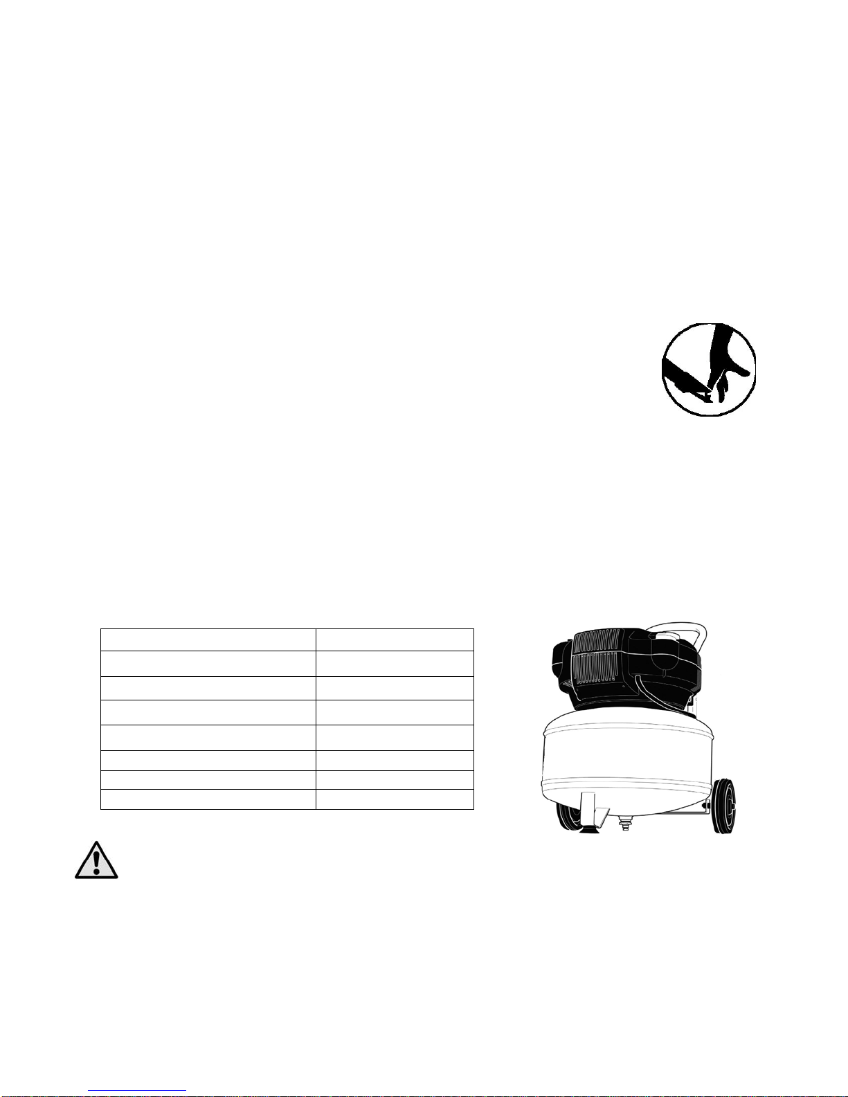
•Oil-less air compressors are factory lubricated for life and do not
require any further lubricated.
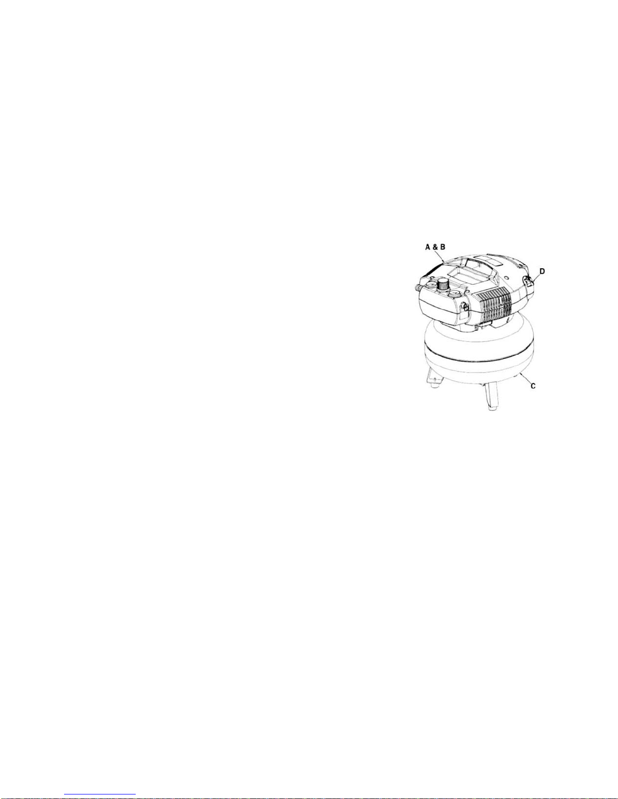
•The basic components of the air compressor are the electric motor,
pump, pressure switch, and tank. The electric motor (A) powers the
pump. The electric motor is equipped with an overload protector and
an automatic reset. If the motor becomes overheated, the overload
protector will shut it down to prevent damage to the motor. When the
motor cools sufficiently, it will automatically restart.
•The pump (B) compresses the air and discharges it into the tank.
•The tank (C) stores the compressed air.
•The pressure switch (D) shuts down the motor and relieves air
pressure in the pump and transfer tubwhen the air pressure in the tank
reaches the kick-out pressure. As compressed air is used and the
pressure level in the tank drops to the kick-in pressure, the pressure switch restarts the motor
automatically, without warning, and the pump resumes compressing air.
Fig 1
Assembling the Compressor
1.Unpack the air compressor. Inspect the unit for damage. If the unit has been
damaged in transit, contact the carrier and complete a damage claim. Do this
immediately as there is a time limit to damage claims. The carton should contain:
- Air compressor
- Operator and parts manuals
- Handle
- 3/8” x 25’ Air Hose (x1)
2.Tighten the handle into its position with the screws included.
3.Check the compressor’s specifications label to ensure that you have received the model ordered,
and that it has the required pressure rating for its intended use.
4.Locate the compressor according to the following guidelines:
a. Position the compressor near a grounded electrical outlet (see GROUNDING INSTRUCTIONS,
above).
b.The compressor must be at least 12”(31 cm) from any wall or obstruction, in a clean,
well-ventilated area, to ensure sufficient air flow and cooling.

c.In cold climates, store portable compressors in a heated building when not in use. This will reduce
problems with motor starting and freezing of water condensation.
d. Remove the compressor from the shipping pallet orcarton and place it on the floor or ahard, level
surface. The compressor must be level to ensure proper drainage of the moisture in the tank.
5.Connect an air hose (not included) to the compressor hose outlet.
Compressor Controls
Fig 2
A. Pressure switch: This switch turns the compressor ON. It can be operated manually, but
when in the ON position, it allows the compressor to start up or shutdown automatically, without
warning, on demand. ALWAYS set this switch to OFF
B. Pressure Relief Valve: If the pressure switch does not shut down the motor when the
pressure reaches the preset level, this valve will pop open automatically to prevent
over-pressurization. To operate manually, pull the ring on the valve to relieve air pressure in the
tank.
C. Tank Pressure Gauge: This gauge measures the pressure level of the air stored in the tank.
It is not adjustable by the operator, and does not indicate line pressure.
D. Air Pressure Regulator: This air pressure regulator enables you to adjust line pressure to
the tool you are using.
WARNING! NEVER EXCEED THE MAXIMUM WORKING PRESSURE OF THE TOOL.
TURN THE KNOB CLOCKWISE TO INCREASE PRESSURE, AND COUNTER-CLOCKWISE
TO DECREASE PRESSURE.
E. Regulated pressure gauge: This gauge measures the regulated outlet pressure.
F. Regulated pressure quick connect coupler: This coupler connects to the regulated outlet
pressure. To connect air hose, push coupler in.
To disconnect air hose, pull the coupler collar back.
Electrical Power Requirements
Electrical Wiring
Refer to the air compressor’s specifications label for the unit’s voltage and amperage requirements.
Use a dedicated circuit. For best performance and reliable starting, the air compressor must be
plugged into a dedicated circuit, as close as possible to the fuse box or circuit breaker. The
compressor will use the full capacity of a typical 15 A household circuit. If other devices are on the
same circuit, the compressor may fail to start. Low voltage or an overloaded circuit can result in
sluggish starting that causes the motor overload protection system circuit breaker to trip, especially in
cold conditions.
Manual 58-7992 V 1.7– 8 Gallon compressor
2005-7-19
9

Note: A circuit breaker is recommended. If the air compressor is connected to a
circuit protected by a fuse, use dual element time delay fuses (Buss Fusetron type “1”
only).
Extension Cord
Note: Avoid use of extension cords.
For optimum performance, plug the compressor power cord directly into a grounded wall socket. Do
not use an extension cord unless absolutely necessary. Instead, use a longer air hose to reach the
area where the air is needed.
If use of an extension cord cannot be avoided, the cord should be no longer than 100’ and be a
minimum wire size of 12 gauge (AWG). Do not use a 16 or 14 gauge extension cord.
Use only a three-pronged extension cord that has a 3-pronged grounding plug, and a 3-slot receptacle
that will accept this plug. Make sure your extension cord is in good condition. An undersized
cord will cause a drop in line voltage, resulting in loss of power and overheating. The smaller
the gauge number, the heavier the cord.
Grounding Instructions
This product should be grounded. In the event of an electrical short circuit or current leakage,
grounding reduces the risk of electric shock by providing a path for the electric current. Consult with an
electrician if necessary.
This product is equipped with a three-pronged grounded power cord and plug. The plug must be
plugged into an outlet that is properly installed and grounded accordance with all local codes and
ordinances. Never modify the plug.
WARNING! IMPROPER INSTALLATION OF THE GROUNDING PLUG
CAN RESULT IN A RISK OF ELECTRIC SHOCK. IF REPAIR OR
REPLACEMENT OF THE CORD OR PLUG IS NECESSARY, DO NOT
CONNECT THE GROUNDING WIRE TO ANY FLAT BLADE TERMINAL. THE
GROUND WIRE IS EITHER GREEN WITH OR WITHOUT YELLOW STRIPES
AND MUST BE CONNECTED TO THE "GROUND" PIN OF THE PLUG.
This product is for use on a nominal 115 V, 15 A circuit. An outlet with a grounding plug must be
used.
Make sure that the product is connected to an outlet with the same configuration as the plug. No
adaptor should be used with this product.
Breaking in the Pump
1. Turn the pressure switch to the OFF position (A, Fig 2).
2. Pull the pressure relief valve.
3. Open the regulator valve (D, Fig 2). Turning counter-clockwise.
4. Plug in the power cord.
5. Turn the pressure switch to the ON position (C, Fig 2). The compressor will start. Allow the
compressor to run for 15 minutes, to break in the internal parts.
CAUTION: AFTER ABOUT 15 MINUTES IF THE UNIT DOES NOT OPERATE
PROPERLY SHUT DOWN IMMEDIATELY AND CONTACT A SERVICE CENTER.
Manual 58-7992 V 1.7– 8 Gallon compressor
2005-7-19
10

6. After about 15 minutes, turn the pressure switch to the OFF position.
7. Close the air pressure regulator by turning it clockwise. Turn the pressure
switch to ON. The tank will now fill.
Note:As compressed air is used, the pressure switch will restart the motor automatically.
Note: During the initial break-in cycle, there will be a slight electrical smell as the motor brushes seat.
This is normal for universal motors and will last for about 5 minutes.
Operating Instructions Daily Startup
1 Turn the pressure switch to the OFF position (A, Fig. 2).
2 Close the air pressure regulator (D, Fig 2). Turn clockwise.
3 Plug in the power cord.
WARNING! HIGH TEMPERATURES ARE GENERATED BY THE ELECTRICAL MOTOR
AND THE PUMP. TO PREVENT BURNS OR OTHER INJURIES, DO NOT TOUCH THE
COMPRESSOR WHILE IT IS RUNNING. ALLOW IT TO COOL BEFORE HANDLING OR
SERVICING. KEEP CHILDREN AWAY FROM THE COMPRESSOR AT ALL TIMES.
4 Turn the pressure switch to the ON position (C, Fig 2).
WARNING! WHEN ADJUSTING FROM A HIGHER TO A LOWER PRESSURE, TURN THE
KNOB COUNTER-CLOCKWISE TO REACH THE DESIRED PRESSURE. DO NOT EXCEED
OPERATING PRESSURE OF THE TOOL OR ACCESSORY BEING USED.
5 Adjust the regulator to the working pressure of the tool.
Shutdown
1 Turn the pressure switch to the OFF position (A, Fig 2).
2 Unplug the power cord.
3 Reduce pressure in the tank through the outlet hose. You can also pull the relief
valve ring (B, Fig. 2) and keep it open to relieve pressure in the tank.
WARNING! ESCAPING AIR AND MOISTURE CAN PROPEL DEBRIS THAT MAY CAUSE
EYE INJURY. WEAR SAFETY GOGGLES WHEN OPENING THE DRAIN VALVE.
4 Tip the compressor (if necessary for your model) so the drain valve is at the
bottom of the tank(s). Then open the drain valve (B, Fig 2) to allow moisture to
drain from the tank.
Maintenance
WARNING! TO AVOID PERSONAL INJURY, ALWAYS SHUT OFF AND UNPLUG THE
COMPRESSOR, AND RELIEVE ALL AIR PRESSURE FROM THE SYSTEM BEFORE
PERFORMING ANY SERVICE ON THE AIR COMPRESSOR.
Regular maintenance will ensure trouble free operation. Your electric powered air compressor
represents high quality engineering and construction; however, even high quality machinery
requires periodic maintenance. The items listed below should be inspected on a regular basis.
Manual 58-7992 V 1.7– 8 Gallon compressor
2005-7-19
11

Draining the Tank
Relieve the air pressure in the system and open the drain valve on the bottom of the tank to drain.
WARNING! CONDENSATION WILL ACCUMULATE IN THE TANK. TO PREVENT
CORROSION OF THE TANK FROM THE INSIDE, THIS MOISTURE MUSTBE DRAINED AT THE
END OF EVERY WORKDAY. BE SURE TO WEAR PROTECTIVE EYEWEAR.
Note: In cold climates, drain the tank after each use to reduce problems with
freezing of water condensation.
Checking the Relief Valve
Pull the pressure relief valve daily to ensure that it is operating property and to clear the valve of any possible
obstructions.
Testing for Leaks
Check that all connections are tight. A small leak in any of the hoses or pipe connections will
substantially reduce the performance of your air compressor. If you suspect a leak, spray a small
amount of soapy water around the area of the suspected leak with a spray bottle. If bubbles appear,
repair or replace the faulty component. Do not over tighten any connections.
Storage
Before storing the compressor for a prolonged period, use an air blow gun to clean all dust and
debris from the STORAGE compressor. Disconnect the power cord and coil it up. Pull the pressure
relief valve to release all pressure from the tank. Drain all moisture from the tank. Cover the entire
unit to protect it from moisture and dust.
Service
Perform the following maintenance at the intervals indicated below:
•Operate the pressure relief valve: Daily
•Drain tank: Daily
Manual 58-7992 V 1.7– 8 Gallon compressor
2005-7-19
12

Manual 58-7992 V 1.7– 8 Gallon compressor
2005-7-19
13
TROUBLESHOOTING
Note: Troubleshooting problems may have similar causes and solutions.
PROBLEM
POSSIBLE CAUSE SOLUTION
Low pressure
Not enough air
Compressor
does not stop
•Tank Pressure Relief valve is open.
•Prolonged excessive use of air.
•Compressor not large enough.
•Restricted check valve.
•Tank leaks.
•Blown seal(s).
- Close valve
- Decrease use
- Check air requirement of accessory.
If it is higher than CFM and pressure
supplied by the compressor, you need
a larger compressor. Most accessories
are rated at 25% of actual CFM while
running continuously.
- Remove and clean or replace.
Hole in air hose, check and replace if
necessary.
- Replace tank immediately.
DO NOT ATTEMPT TO REPAIR.
- Replace any faulty seals.
- Replace worn parts and reassemble
with new seals.
Excessive
starting and
stopping while
not in use
•Fittings leak.
•Air leaks from regulator, or regulator
does not regulate pressure.
•Regulated pressure gauge reading
drops when air accessory is being
used.
- Check fittings for leaks with soapy
water. Tighten or reseal leaking
fitting(s). DO NOT OVERTIGHTEN.
- Replace worn parts and reassemble
with new seals. Replace any faulty
seals.
- Dirty or damaged regulator internal
parts.
- This is normal.
- Compressor not large enough.
- If pressure drops too low, adjust
regulator while using the accessory.
- Check air requirement of accessory.
If it is higher than the CFM and
pressure supplied by the compressor
you need a larger compressor. Most
accessories are rated at 25% of actual
CFM while running continuously.
Circuit breaker
trips (fuse •Low voltage.
- Consult an electrician.

Manual 58-7992 V 1.7– 8 Gallon compressor
2005-7-19
14
Circuit breaker/
fuse trips. Often •Excessive wire length causes
voltage to drop too much.
•Restricted air passages.
•Back pressure in pump head.
- Link additional air hoses together to
acquire additional length;
DO NOT USE AN EXTENSION CORD
- Contact authorized service centre.
- Replace check valve and/or pressure
switch bleeder valve.
Overheating •Poor ventilation.
•Dirty cooling surfaces.
•Leaking valve.
- Relocate compressor to an area with
cool, dry and well-circulated air.
- Clean all cooling surfaces of pump
and motor thoroughly.
- Replace worn parts and reassemble
with new seals.
Motor Stalls •Low Voltage.
•Defective pressure switch bleeder
valve.
- Link additional air hoses together to
acquire additional length;
DO NOT USE AN EXTENSION CORD
- Replace pressure switch bleeder
valve.
Pressure relief
valve opens •Tank pressure has exceeded
normal operating pressure.
•Pressure switch is stuck
- Replace pressure switch.
Motor will not
run •Tank pressure exceeds preset
pressure switch limit.
•Motor overload protection has been
tripped.
•Fuse blown or circuit breaker
tripped.
- Motor will start automatically when
tank pressure drops below kick-in
pressure of pressure tank.
- Allow the motor to cool off and the
overload switch will automatically reset.
This may take several minutes.
- Replace blown fuse or rest circuit
breaker. Do not use fuse or circuit
breaker with higher rating than specific
for your circuit branch. Check for
proper fuse; ‘Fusetron’ Type T is
acceptable.
- Check for low voltage and discontinue
use of extension cord.
- Disconnect other applications from
circuit.
- Operate compressor on a dedicated
circuit.
- Remove and clean or replace.

Manual 58-7992 V 1.7– 8 Gallon compressor
2005-7-19
15
•Check valve stuck open.
•Pressure bleeder valve on pressure
switch has not unloaded head
pressure.
•Compressor attached to extension
cord.
•Loose electrical connections.
•Paint spray on internal motor parts.
•Possible defect motor.
- Bleed line by moving pressure switch
lever to OFF position before restarting.
If bleeder valve does not open, replace
bleeder valve.
- Link additional air hoses together to
acquire more length;
DO NOT USE AN EXTENSION CORD
-Contact authorized service centre.
- Have checked at service centre. Do
not operate compressor in a paint
spray area.
- Have checked at a service centre.
Glossary of Terms
CFM: Cubic feet per minute; a unit to measure air flow.
PSI: Pounds per square inch; a unit to measure air pressure,
Kick-in pressure: Factory-set low pressure point that starts the compressor to depressurize the tank
to a higher pressure
Kick-out pressure: Factory-set high pressure point that stops the compressor from increasing the
pressure in the tank above a certain level.
Well-ventilated: An area in which air circulation is sufficient to prevent buildup of potentially
dangerous vapour or particles.
Dedicated circuit: An electrical circuit reserved for the exclusive use of the air compressor.
ASME (American Society of Mechanical Engineers): Indicates that the components are
manufactured, tested and inspected to the specifications set by ASME.
CSA (Canadian Standards Association): Indicates that the products that have this marking have
been manufactured, tested and inspected to standards that are set by CSA.
Manual 58-7992 V 1.7– 8 Gallon compressor
2005-7-19
16

Manual 58-7992 V 1.7– 8 Gallon compressor
2005-7-19
16
LIMITED WARRANTY
Trileaf Distribution warrants to the original purchaser that the product covered under this warranty
is free from defects in material and workmanship for one (1) YEAR limited warranty on air
compressor components.
Trileaf Distribution will repair or replace, at its option, products or components which have
failed within the warranty period. Service will be scheduled according to the normal work flow
and business hours at the service centrelocation, and the availability of replacement parts.
All decisions with regard to this limited warranty shall be final.
RESPONSIBILITY OF ORIGINAL PURCHASER :
• To process a warranty claim on this product, DO NOT return the tool to the retailer. The
product must be evaluated by anAuthorized Warranty Service Centre. For the location of the
nearest Authorized Warranty Service Centre call 1-877-888-3872, between 9:00 AM and
5:00 Monday to Friday.
• Retain original sales receipt as proof of purchase for warranty work.
• Use reasonable care in the operation and maintenance of the product as described in the
Owner’s Manual(s).
• Deliver or ship the product to the nearest Authorized Warranty Service Centre. Freight
costs, if any, must be paid by the purchaser.
•
THIS WARRANTY DOES NOT COVER:
• Merchandise sold as reconditioned, used as rental equipment, and floor or display
models.
• Merchandise that has become damaged or inoperative because of ordinary wear, misuse,
cold, heat, rain, excessive humidity, freeze damage, use of improper chemicals,
negligence, accident, failure to operate the product in accordance with the instructions
provided in the Owners Manual(s) supplied with the product, improper maintenance, the
use of accessories or attachments not recommended by the manufacturer, or
unauthorized repair or alterations.
• An air compressor that pumps air more than 50% during a one hour period is considered
misusedbecause the air compressor is undersized for the required air demand.
• Repair and transportation costs of merchandise determined not to be defective.
• Costs associated with assembly, adjustments or other installation and start-up costs.
• Expendable parts or accessories supplied with the product which are expected to become
inoperative or unusable after a reasonable period of use, including but not limited to
sanding disks or pads, saw and shear blades, grinding stones, springs, chisels, nozzles,
o-rings, air jets, washers and similar accessories.
• Merchandise sold which has been manufactured by and identified as the product of
another company such as gasoline engines. The product manufacturer's warranty, if any,
will apply.
• ANY INCIDENTAL, INDIRECT OR CONSEQUENTIAL LOSS, DAMAGE, OR EXPENSE
THAT MAY RESULT FROM ANY DEFECT, FAILURE OR MALFUNCTION OF THE
PRODUCT IS NOT COVERED BY THIS WARRANTY.
• IMPLIED WARRANTIES, INCLUDING THOSE OF MERCHANTABILITY OR FITNESS
FOR A PARTICULAR PURPOSE, ARE LIMITED TO ONE YEAR FROM THE DATE OF
ORIGINAL PURCHASE.

Parts List
No Description Qty No Description Qty
1 screw M6X25 1 36 outlet valve support 1
2 rubber support 1 37 valve plate 1
3 air tank 1 38 inlet valve plate 1
4 drain valve 1 39 washer 1
5 wheel 2 40 cylinder 1
6 nut M8X40 2 41 hex screw M6X35 3
7 screw M6X35 4 42 washers 3
8 kit 1 43 strap wheel 1
9 handle 1 44 stator 1
10 safety valve 1 45 armature 1
11 air tube 1 46 cover 1
12 screw ST4X20 13 47 hex screw M5X95 2
13 pressure valve 2 48 connection plate 2
14 valve support 1 49 fan 1
Manual 58-7992 V 1.7– 8 Gallon compressor
2005-7-19
17

Manual 58-7992 V 1.7– 8 Gallon compressor
2005-7-19
18
15 1/4" air nozzle 1 50 fan cover 1
16 1/4" X1/4" tie-in 1 51 valve 1
17 1/4" X1/4" fix ring 1 52 connector 1
18 copper nut 2 53 C5 washer 2
19 copper tube 1 54 plug of air nozzle 2
20 screw M10X25 1 55 screw M5X10 2
21 6203 bearing 3 56 ground wire 2
22 connecting rod 1 57 air pressure switch 1
23 piston ring 1 58 strap 1
24 black plate 1 59 transmission shaft 1
25 M6X15 hex screw 1 60 eccentric wheel 1
26 copper tube 1 61 motor support 1
27 1/2" X1/2" fix ring 1 62 stator washer 1
28 fuse 1 63 over heat sensor 1
29 upper cover 1 64 screw ST4.2X15 1
30 1/2" X1/2" plug 1 65 strain relief 1
31 Hex bolt M6X105 4 66 power cable 1
32 cylinder head 1 67 6000 O ring 2
33 exhaust 1 68 carbon brush assembly 2
34 washer 1 69 screw ST4X10 4
35 head gasket 1 70 lower cover 1
Table of contents