YORK INTERNATIONAL8
FORM 220.11-NM2 (602)
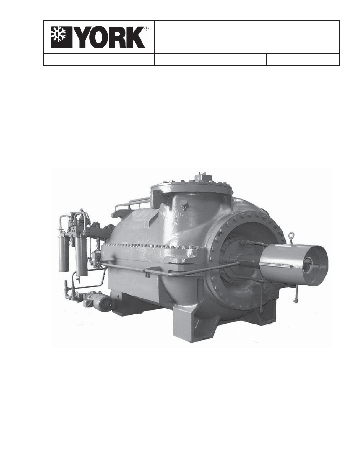
Description of System and Fundamentals of Operation
The internal stationary seals can be supplied in alumi-
num, bronze, or coated cast iron depending on the appli-
cation. The impeller diameter(s), blade width, and posi-
tion on the rotor can be varied to permit the introduction
of side load connection(s) if required. There can be side
load flows into several different stages and they can en-
ter into the bottom or top half of the compressor casing
as needed to accommodate the application.
Bearings
The compressor is equipped with aluminum sleeve
taper-bore or taper-land journal bearings, with the size
of the suction end bearing being varied as a function of
shaft horsepower. The thrust bearing system can incor-
porate hydrostatic bearings in the active (shaft move-
ment toward coupling) and reverse directions, tilting
pad in the active with hydrostatic in the reverse direc-
tion, or tilting pad in both active and reverse directions.
Temperature Sensors and Proximity Probes
The compressor may be equipped with bearing tem-
perature sensors and/or proximity probes for purposes
of monitoring compressor shaft vibration and/or axial
thrust position.
Seals
The compressor is equipped internally with gas/oil seals
over wind-back spirals on the shaft to control oil from
entering the compressor casing. There is also an atmo-
spheric shaft seal to minimize leakage of oil and pro-
cess gas to the outside where the shaft passes through
the housing. Some leakage from this seal is normal with
the rate being dependent on shaft speed, coupling di-
ameter, and pressure differential across the seal. There
is a provision for that fluid to be directed to an atmo-
spheric drain trap cast into the leg of the main casing.
Bolt Patterns
Due to the varied application of this compressor fam-
ily, there can be differences in the bolting and the pat-
terns of the bolting. There will be more bolts utilized
in the external patterns when the compressor is designed
for a higher design working pressure. There can be
variations on the internal bolting strength and sizing if
the application requires resistance to the effects of cer-
tain corrosion phenomenon. The application drawings
will indicate these special circumstances with special
bolt torque values or notes regarding special identify-
ing features such as “redrawn screws will have green
bolt heads.”
As Built Drawings
It is difficult to define the parameters of a standard mul-
tistage compressor although the typical two stage com-
pressor applied on a water chilling / air conditioning
duty is the most common type.
It is imperative to have the “as built”
drawings for the specific compressor
on hand before ordering spare parts
or attempting to work inside the com-
pressor. Failure to do so could result
in damage to the machine.
SAFETY
It is recommended that all maintenance and service re-
pair work be performed by experienced personnel.
There must be recognition of the potential hazards that
can exist. Those hazards may include (but are not lim-
ited to);
There can be electrical circuitry that
presents an electrocution hazard. Be
sure that the source of all power sup-
plies have been properly isolated and
secured before attempting any service
related activities.
The unit must have the coupling
guards in place and fully attached at
any time the shafts will be rotating. Be
sure that the shafts have stopped com-
pletely and the main power source has
been properly isolated before attempt-
ing any service related work activities
on the system.