DAVIS eVO DVC10-A7KGP1E User manual

1
DAVISeVO EV AC Charger
Installation and Operation Manual
DVC10-A7KGP1E
DVC10-A11KGP1E
DVC10-A22KGP1E
Document version V1.0

2
Copyright Information
"All content and visuals within this manual are protected by copyright and are the intellectual property of Davex Engineering (M)
Sdn. Bhd. Unauthorized reproduction, extraction, or use of the content is strictly prohibited without prior authorization from one of
our company's representatives. If you have received authorization to use the content in this manual, you must adhere to the terms
of the authorization and provide proper attribution to the 'source of content.' Please be aware that any violation of this statement
may result in legal consequences.
Disclaimer of Warranties and Limitation of Liabilities
The specifications, illustrations, and information in this manual are based on the latest data provided by our technicians. DAVIS
LIGHTING reserves the right to update the manual without prior notice. While every effort has been made to ensure the accuracy
of the information in this manual, including product specifications, features, and illustrations, no guarantee is provided regarding
the completeness of its content.
DAVIS LIGHTING shall not be held liable for any direct, special, incidental, or indirect damages, including consequential
economic loss (such as loss of profits).
IMPORTANT
Before operating or maintaining this charger, please read this manual carefully, paying extra attention to the safety warnings and
precautions.

3
Safety Information
In order to ensure safety for yourself and others, and to prevent damage to your vehicle and charger, please carefully read and
strictly follow the instructions and warning statements provided in this manual for charger operation. It is of utmost importance to
prohibit children from using this equipment, and parents should closely supervise their children when they are near the charger.
DANGER
Operators must steer clear of these hazardous conditions and adhere to local safety standards when operating the equipment.
Failure to do so may result in serious injuries and other significant losses.
WARNING
Indicates a potentially harmful situation. To prevent harm, it's essential to comply with relevant standards. Failure to do so could
lead to serious injury and losses.
Safety Instructions
The following safety warnings cover most situations that DAVIS LIGHTING is aware of. However, DAVIS LIGHTING cannot
anticipate or advise on all possible warnings. It is crucial to verify the operational procedures to ensure both your personal safety
and the proper functioning of the charger.
SAFETY WARNINGS
•Engineers in charge of charger installations must hold electrical licenses in compliance with local laws and regulations.
•Ensure that the chargers are securely and reliably grounded, and that the ground connections comply with local standards
and criteria.
•Do not install or use this charger near flammable, explosive, harsh, or combustible materials, chemicals or vapors.
•Supervise children around the charger and prohibit them from operating it.
•Do not insert fingers or foreign objects into the electric vehicle connector.
•Do not use the charger if the flexible power cord or EV cable shows signs of being frayed, broken, or damaged.
•It is recommended to use copper conductors with 105℃wire insulation (UL1015).
•Do not operate the charger outside its operating temperature range of -13 to 131 °F (-25 to 55 °C).
•Incorrect installation and testing of the charger could potentially damage the vehicle's battery, components, or the charger
itself.
•Handle the charger with care during transportation. Do not subject it to strong force or impact or pull to prevent damage to
it or other components.

4
Catalogue
Catalogue ..................................................................................................................................................................4
1. About this manual ..................................................................................................................................................5
1.1 Using this manual.........................................................................................................................................5
1.2 Applicable areas...........................................................................................................................................5
1.3 Applicable group...........................................................................................................................................5
1.4 Illustration .....................................................................................................................................................5
1.5 How to use this manual................................................................................................................................5
1.6 General Introduction.....................................................................................................................................5
1.7 Abbreviations and term ................................................................................................................................6
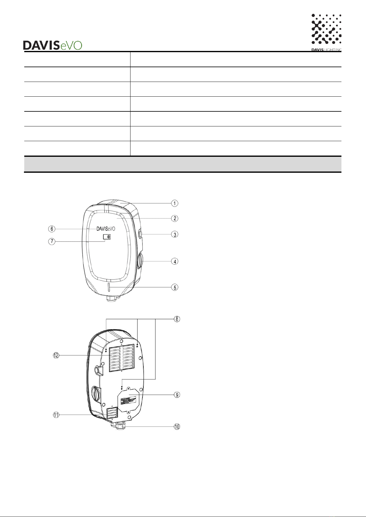
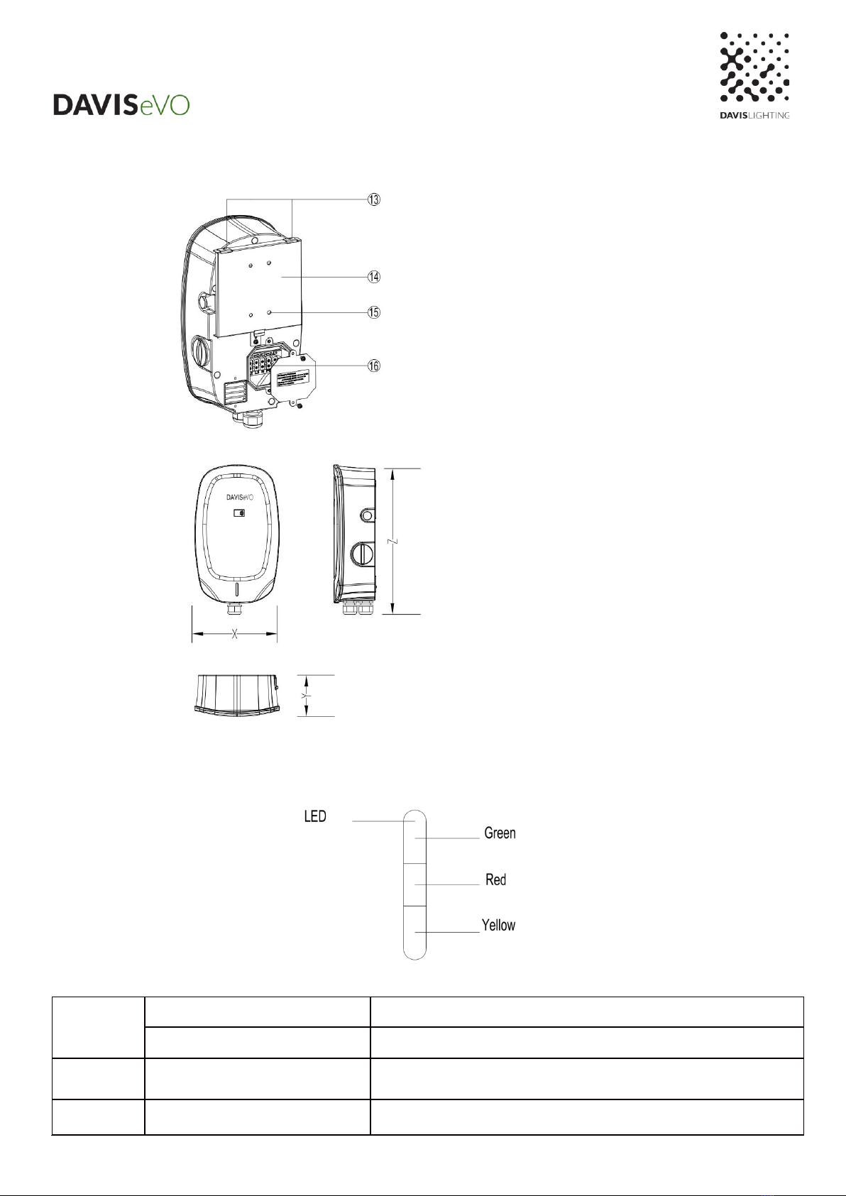
1.8 Product Overview..................................................................................................................................... 6,7
1.9 LED indicator................................................................................................................................................7
2. Specifications ........................................................................................................................................................8
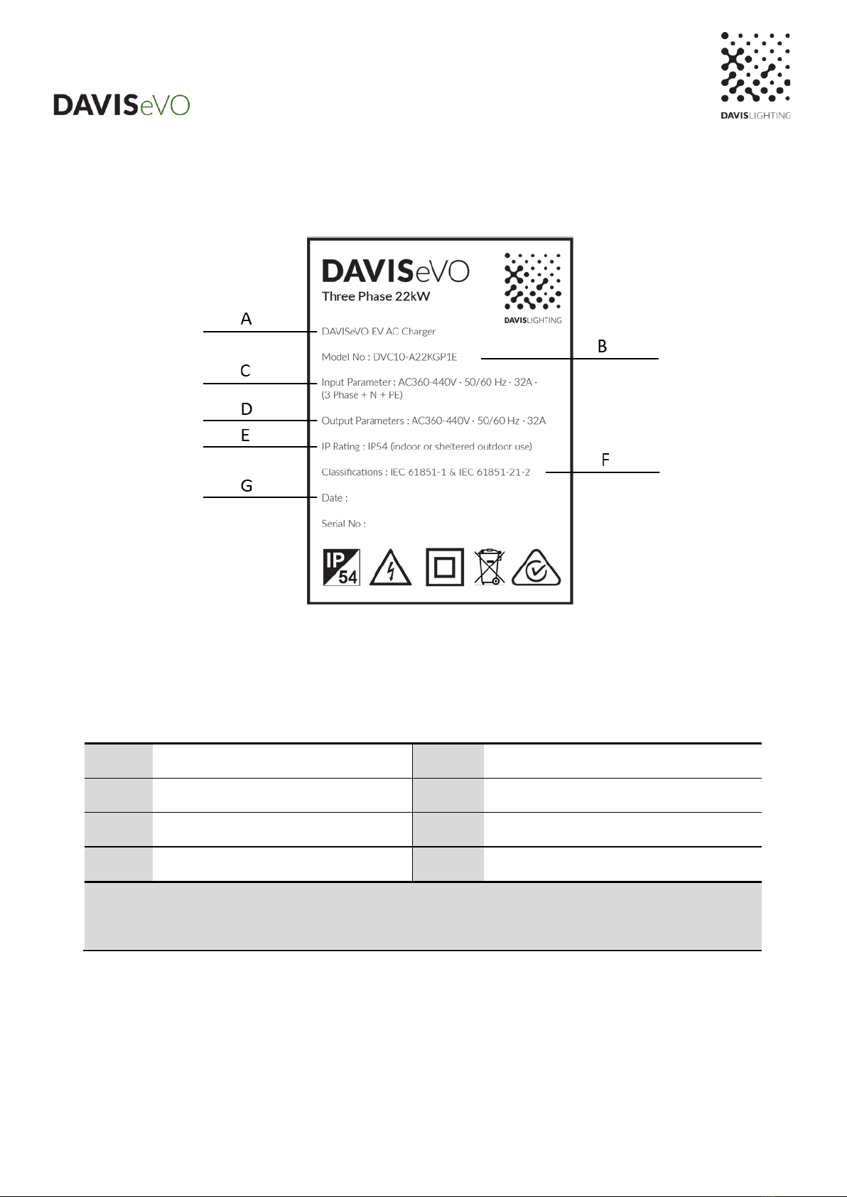
2.1 Product name plate......................................................................................................................................8
2.2 Product technical parameters ................................................................................................................ 9,10
3. Preparation for charger installation...................................................................................................................111
3.1 General requirements ..............................................................................................................................111
3.2 Environment and tool requirements.........................................................................................................111
3.3 Unpack the charger..................................................................................................................................111
4. Electrical installation of charger ..........................................................................................................................12
4.1 General Specification .................................................................................................................................12
4.2 Electrical installation procedure .................................................................................................................13
5. Mechanical installation of the Charger................................................................................................................15
5.1 Installation procedure of power distribution module (Optional) .................................................................15
(1) Cable hole pre-treatment.....................................................................................................................15
(2) Power distribution module cable connection.......................................................................................15
(3) Power distribution module installation.................................................................................................15
5.2 General Specification .................................................................................................................................16
5.3 Support rear plate mounting ......................................................................................................................17
5.4 Mounting bracket installation .....................................................................................................................17
5.5 Installation the whole Charger ...................................................................................................................18
5.6 End and check............................................................................................................................................18
6. Charger power supply operation.........................................................................................................................18
6.1 Power on operation....................................................................................................................................18
6.2 Close the Charger power switch................................................................................................................19
6.3 Power-off operation....................................................................................................................................19
7. Maintenance and fault diagnosis.........................................................................................................................20
7.1 Maintenance...............................................................................................................................................20
7.2 Fault diagnosis ...........................................................................................................................................20
8. DAVIS LIGHTING Service...................................................................................................................................22

5
1. About this manual
1.1 Using this manual
•This manual is only applicable to the installation and operation of DVC10 series 7KW, 11KW and 22kW AC power supply
Charger.
•This manual provides the information required to perform the following work:
oInstallation work of the charger.
oDaily fault diagnosis and maintenance of the charger.
•The manual may be updated with the product upgrade iteration, but the change may not affect the normal reading and
execution of the user.
1.2 Applicable areas
This manual is applicable to the EU Community countries and other areas that use charging standard IEC61851-1&
IEC61851-21-2.
1.3 Applicable group
•This manual is designed for qualified engineers with electrical license.
•In addition to being used by professional engineers, users can also strictly follow the process described in this document
to perform simple maintenance.
1.4 Illustration
The illustrations in this document have shown most of the product information including some normal functions and typical
settings of the product.
1.5 How to use this manual
It is essential to comprehend all the contents of this manual before using the charger to ensure proper operation.
1.6 General Introduction
The DAVIS DVC10 series AC charger is designed for charging electric vehicles or plug-in hybrid electric vehicles in your home
or apartment. Our chargers provide safe, reliable, fast, and intelligent charging solutions. The primary difference between the
DAVIS 7KW, 11KW, and 22KW EV AC chargers is the electrical installation type, with the latter two (11KW and 22KW)
supporting 400V voltage input. However, the installation procedures for all three models are similar. This manual describes the
installation steps for both single-phase and three-phase inputs and provides instructions on how to install and use the charger.
You can also access the chargers via Wi-Fi, control them, and check their status through a mobile app.
Intended Use
The DAVISeVO EV AC charger for home is designed for the AC charging of electrical vehicles (EVs). It is suitable for both indoor
and sheltered outdoor use.
Note: The images and illustrations description in this manual may differ slightly from the actual product.
1.7 Abbreviations and term
Abbreviations
Definition

6
AC
Alternating current power supply
DC
Direct current power supply
EMC
Electromagnetic compatibility
EV
Electric vehicle
EVSE
Electric vehicle power supply Charger
RFID
Radio frequency identification
PE
Protective ground
Note: All terms may not be explained in this manual, which may help the engineer understand the operation about the Charger.
1.8 Product overview
1Charger main body cover
2Front cover plate
3Emergency stop button
4Maintenance hole
5 Indicator
6Manufacturer Logo
7RFID Reader
8 Mounting hole
9Rear maintenance cover plate
10 Bottom AC inlet and outlet hole
11 Heat dissipation air inlet
12 Heat dissipation air outlet
Note: Heat dissipation fan is only equipped on the 22KW charger.

7
1.8 Product Overview
1.9 LED indicator
Green
Solid Green
The charger is on standby / A charging session has ended
Not illuminated
The charger is off
RED
Solid Green and Red
The charger is faulty
Yellow
Solid Yellow and Green
The charger is charging the vehicle
XWidth of the charger
YDepth of the charger
ZHeight of the charger
X: 230 mm Y: 115 mm Z: 375 mm
13 Mounting bracket
14 Rear plate
15 Wall installation hole
16 AC wire connector

8
2. Specifications
2.1 Product name plate
A
Product name
E
Protection degree
B
Product model
F
Implementation standards
C
Input characteristics
G
Production date and bar code
D
Output characteristics
-
-
Note: The data in the figure is only a reference and does not represent the physical nameplate of the product. To
view the applicable data, find the nameplate on the charger.

9
2.2 Product technical parameters
Electrical parameters
Model
DVC10-A7KGP1E
DVC10-A11KGP1E
DVC10-A22KGP1E
Comment
Input
parameters
Input
mode
Single-phase three-
wire
Three-phase five-wire
Note: The product
is suitable for T-N
system.
Voltage
range
220-240Vac
360-440Vac
Note: The product
works normally
within this voltage
range.
Frequency
range
45~65 Hz
-
Rated
frequency
50/60 Hz
-
Rated
voltage
230Vac
400Vac
-
Rated
current
≤32A
≤16A
≤32A
-
Output
parameters
Rated
voltage
230Vac
400Vac
Note: The output
voltage varies
with the input
voltage.
Rated
current
≤32A
≤16A
≤32A
-
Rated
power
7 kW
11 kW
22 kW
-
Power factor
≥0.99
Rating condition
Efficiency
≥99.5%
Rating condition
Standby power consumption
≤5 W
Rating condition
Current measurement range
10mA~50A; ±0.5%
10mA~25A; ±0.5%
10mA~50A; ±0.5%
-
Accuracy class
Level 1.0
-
Input protection type
Type A RCD; ≤30mA
-
Protective function
Leakage current protection; Over current protection; Short circuit
protection; Detection gun disconnection protection; Grounding protection,
over-voltage and under-voltage protection; Load imbalance protection
(only applies to three-phase five-wire).
Note: Lightning
protection for its
own control core.
Input connector
3 Pin terminal
5 Pin terminal
Note:8~10 AWG
Charge
interface
Quantity
One
-
Length
Charging gun wire, total length 5m (including 0.3m)
Note:
Customizable.
Type
EN IEC 62196-2016: AC Type 2
-
Insulation
Input to
Under normal atmospheric pressure, in the environment of relative humidity
-

10
Resistance
Output
≤ 90%,the insulation resistance between each live circuit and between the
live circuits and the ground is not less than 10MΩ at 1000V DC voltage.
Input to PE
Output
to PE
Withstand
voltage
Input to
Output
AC2500V/1min/10mA
-
Input to PE
AC2500V/1min/10mA
-
Output
to PE
AC2500V/1min/10mA
-
Leakage
current
<5mA(230V ac /400V ac 、50/60Hz input)
-
System parameters
Standby power
<5W
-
Shell Material
Plastic (ABS+PC)
-
Panel Material
Plastic (ABS+PC)
-
Appearance Size
width* height*depth:230*375*115(mm)
Tolerance ±2mm.
Network communication
2.4G WIFI Network
-
Networking Protocols*
Customizable OCPP1.6J
-
Start-up method
Swipe card to start, network to start (mobile APP)
-
charging method
Full of intelligence
-
Cool-down method
Natural cooling
Intelligent air cooling
-
Protection
IP54
Application environment
Indoor and outdoor parking charging station
Weight
About 3.5kg
About 4kg
About 5kg
Installation
Wall mounted installation; column type(option)
Accessories list
1. Charger; 2. Quick Reference Guide; 3. Factory test report; 4. RFID
card; 5. Mounting bracket; 6. Support rear plate; 7. Screws

11
3. Preparation for charger installation
3.1 General requirements
•Obtain permission to install this charger in accordance with local regulations.
•The AC power supply is accessible at the installation location.
•Ensure that the power cable is disconnected during installation.
3.2. Environment and tool requirements
Prepare before installation:
•Search and prepare a suitable installation location
•Ensure that the installation location has a wall suitable for mounting the charger. The expansion bolts used to secure the
rear plate should have a bearing capacity of at least 20kg.
•In addition to the above, you may also need to prepare the following tools: Drilling machine, Wire stripper, Crimping pliers
insulation tape, pipe terminals, etc.
3.3 Unpack the Charger
•Remove the charger from its packing case.
•Take out the packing materials and installation accessories, then set them aside
•Check all parts to ensure that all materials have been delivered.
a. Charger
b. RFID card
c. Quick Reference Guide
d. Mounting bracket
e. Support rear plate
f. 5M 4x12 Screws
•Inspect the charger and installation parts for any damage. If there is any damage or if parts are missing, please
contact the local supplier representative or the manufacturer's after-sales service.

12
4. Electrical installation of charger
4.1 General Specification
Before performing any electrical installations, ensure that you have a clear understanding of the following electrical regulations
for the charger:
Wiring terminal definition
Cable requirement
Note: 1. For the DVC10-A7KGP1E charger, the maximum continuous working current is 32A, and the cable must
meet these requirements. We recommend using a 10 AWG cable with a 600Vac withstand voltage rating. However,
you may also opt for a larger cable size.
2. For single-phase AC chargers, the power cable can have a sheath, but its maximum allowable diameter should
not exceed the range shown in the diagram above; otherwise, assembly cannot be completed.
For the charger models DVC10-A11KGP1E and DVC10-A22KGP1E, they are suitable for 360-440Vac three-phase AC power
(TN):
Wiring terminal definition
General Requirement

13
Note: 1. For the DVC10-A11KGP1E charger, the maximum continuous working current is 16A, and the cable
should meet the above requirements. It is recommended to use a 12 AWG cable with a 600Vac withstand voltage
rating.
2. For the DVC10-A22KGP1E charger, the maximum continuous working current is 32A, and the cable
should meet the requirements outlined above. We recommend using a 10 AWG cable with a 600Vac withstand
voltage rating. However, you can opt for a larger cable size if desired.
3. For single-phase AC chargers, the power cable can have a sheath, but its maximum allowable diameter
should not exceed the range shown in the diagram above; otherwise, assembly cannot be completed.
4.2 Electrical installation procedure
Since the connection of the cable is made in the rear plate of the charger, the electrical installation work should be completed
before the mechanical installation.
(1) Cable pre-treatment
•Measure the actual length of the AC power cable according to the installation location of the charger, and pretreat the
cable (If possible, crimp the cable to a tubular terminal for subsequent connection) for preparation.
•Remove the rear plate maintenance cover
•Use a screwdriver to remove the maintenance cover screws, revealing the terminal connected to the AC cable and the
power distribution module.
•Please keep the maintenance cover and fixing screws aside for future use.
A: Wiring terminal; B: Maintenance cover plate;
C: Screws; D: Waterproof seal.
Note: Be sure not to discard the related parts when removing the maintenance cover, such as waterproof seals and securing
screws
(2) Pre-install cables
•Loosen the waterproof jacket of the cable by turning it counterclockwise.
•Insert the pre-treated cable into the waterproof jacket, leaving a cable length of approximately 10~15mm based on the
installation position for easy access to the terminal. (Note: Crimping the cable to a tubular terminal is essential for a
secure connection.)
•To secure the waterproof jacket, turn it counterclockwise until it's tightened.
Loosen the cable waterproof jacket
Cable and waterproof jacket installation

14
(3) Charger AC input cable connection
•Use a screwdriver to unscrew and loosen the fixing screws on the wiring terminals.
•Attach the cable to the appropriate terminal port, following the installation diagram for guidance. Then, use a
screwdriver to secure the screws to the specified torque level. (Recommended torque: Max 2 Nm. / 10.6 Lbf.in)
•Once the connection is made, gently pull the cable with slight force to ensure it remains securely in place. If the cable
doesn't come loose, the connection is secure.
AC input cable wiring diagram for single-phase charger
AC input cable wiring diagram for three-phase charger
Note: 1. Engineers can differentiate the wiring by examining the markings on the terminal row in addition to referring to
the pictures provided above for AC input cable connections.
2. Before connecting the AC input cable to the power grid network, please complete the mechanical installation of
the charger first to ensure safety.
(4) Install the rear plate maintenance cover
•Ensure that you remove any debris that may be left inside the charger after installing the AC input cable.

15
•Before installing the maintenance cover, check the waterproof seal strip to ensure it is correctly installed in the groove.
•Reattach the maintenance cover plate and securely fasten the fixing screws with a screwdriver.
Note: Please refrain from removing the waterproof sealing strip during installation. Doing so may compromise the charger's
waterproofing, allowing water to enter and potentially causing short circuits and damage.
5. Mechanical installation of the Charger
5.1 Installation procedure of power distribution module (Optional)
•When this function module is not attached, please disregard this installation procedure and proceed with the subsequent
mechanical installation.
•This installation procedure involves the removal and installation of the maintenance cover plate.
(1) Cable hole pre-treatment
Identify the wire hole for the power distribution module located at the
charger's bottom. Use appropriate tools like screwdrivers to prepare the
wire holes by removing any obstructing material. Then, open the prepared
sealant shell. Carefully insert the wire into the sealant hole and ensure
it is properly secured.
(2) Power distribution module cable connection
Insert the cable through the glue hole, connect the wires to their corresponding interfaces as defined, and then tighten the fixing
screws.
Install the rear cover plate after the above wiring harness connection is completed.
4 PIN terminal wiring definition
General specification for the wiring
Recommended cables: UL2464-4 * 22 AWG or 24 AWG
four-core wire (or other four-core wire)
Recommended length: The recommended cable length is
not more than 40 meters except in exceptional
circumstances.
(3) Power distribution module installation
Install the module on the side of the charger, then insert the current transfer to the power input wire L (L1, L2, L3 for three-
phase).

16
5.2 General Specification
•The engineer or user should supply four expansion bolts measuring M6x50mm, with a load-bearing capacity of at least
10kg.
•Refer to the detailed charger installation space requirements as follows:
Specific technical data:
parameter
Recommended Specification (mm)
A
≥300
B (Indoor installation)
≥900
B (Outdoor installation)
≥1300
Note: The range of installation size can be selected according to local regulatory requirements or actual installation
conditions of the location.

17
5.3 Support rear plate mounting
•After selecting the installation location, drill the holes on the wall, and the holes aperture should be suitable for the M6
x 50 type expansion bolt. This data can be obtained from the technical parameters of the expansion bolt. Fixing the
installation rear plate to the wall with the expansion bolt. Torque parameters of bolt can be obtained through technical
parameters.
•After installing the rear plate, check to ensure it is properly secured and not loose.
Support rear plate
Rear plate install size
Installation schematic diagram of the support rear plate
A
Expansion bolt
B
Support rear plate
C
Fixing hole
D
Wall installation hole
5.4 Mounting bracket installation
Locate the mounting brackets and fixing screws included in the charger package. Refer to the provided images for the installation
instructions.
Installation Schematic diagram of the support hanging ear
A
Charger main body cover
B
Locating pin
C
Mounting bracket

18
D
M4 x 10 screw
5.5 Installation the whole Charger
•Install the charger into the rear plate from top to bottom, aligning it with the mounting bracket and the mounting holes.
•Use a screwdriver to secure the mounting bracket to the location where it connects with the rear plate.
Installation schematic diagram of the support hanging ear installation
A
Mounting Screw
B
Mounting bracket
C
Mounting rear plate fixed to the wall
D
Charger main body housing
5.6 End and check
•After completing the installation steps mentioned above, you also need to perform the following tasks:
•If the charger does not come with parts for mounting the gun cable, install the necessary parts according to the installation
situation.
•Secure the cable in place using cable ties or other suitable methods.
•Site Cleaning: Dispose of site debris, garbage, and charger packaging boxes correctly after installation. The factory test
report, user manual, and user RFID card should be properly retained by the user.
6. Charger power supply operation
6.1 Power on operation
•Before powering on the charger, ensure that the following steps have been completed:
•Ensure that the procedures for charger installation have been executed correctly.
•Inspect the electrical wires for leakage or incorrect connections to prevent power accidents.
•For safety reasons, it is recommended to power on the charger with the presence of professional personnel.
•Connect the cable to AC power supply network.

19
6.2 Close the Charger power switch
•Turn and unscrew the maintenance cover on the right side to visually inspect the internal charger-residual current
protector. Refer to the schematic diagram for detailed instructions.
•Before closing the residual current charger, press the "RESET" button to reset it; otherwise, the closing operation will
be invalid. Refer to the schematic diagram for detailed instructions.
•Close the switch of the residual current device for 3 to 5 seconds. The charger will emit a "click" sound, and the
green status indicator will remain on, indicating that the charger has started successfully.
•After the charger has started normally, ensure that the maintenance cover is restored to its original position.
Detailed operation is shown in the schematic diagram.
Schematic diagram of the maintenance cover
A
Charger main body cover
B
Residual current charger
C
Maintenance cover
D
Waterproof sealing strip
Schematic
diagram of the
key position of
the residual
current device
Schematic
diagram of the
residual
current device
closing
operation
6.3 Power-off operation
•Perform maintenance work on the charger.
•Conduct charger fault diagnosis.
•Dismantle and dispose of the charger and associated component.

20
7. Maintenance and fault diagnosis
7.1 Maintenance
•Users shall conduct maintenance inspection of the charger, including the following items:
•Check whether the charger power supply cable and charging gun cable are damaged.
•Inspect the charger shell for any signs of damage. If you notice substantial damage, stop using the charger
immediately.
•If feasible, perform this check on a monthly basis.
•Remove the maintenance cover on the side of the charger to visually inspect
this device.
•Press the "T" key on the charger; the protector should trip and disconnect under
normal function. If it does not trip normally, refer to the following chapter for
detailed solutions.
7.2 Fault diagnosis
The following troubleshooting table can be used to check the common faults in the routine maintenance.
This manual suits for next models
2
Table of contents