9
Trollbridge 24 Installation (Cont’d)
6. INSULATE YOUR TERMINALS
During installation, use the provided terminal booties to insulate the wire terminals crimped
to the end of each wire. Unconnected cables will have battery voltage coming from cables
that have already been connected. If these short out to anything or to each other,
you can melt wires, blow fuses, damage equipment, or cause a re.
7. VERIFY BEFORE COMPLETING THE INSTALLATION
Have the second person who is assisting with the installation verify the Trollbridge 24 wire
color and the connection location (such as red wire terminal to positive post of starting/
cranking battery or green wire terminal to the negative (-) post of the trolling motor battery)
before making the ring terminal to battery post and completing the connection for each
wire. Follow the suggestions under SAFEGUARDS on page 6 of this manual as they
are there to protect you, your boat’s equipment, and your new Trollbridge 24.
5. MOUNTING LOCATION
Mount the Trollbridge 24 such that you can see the green Charging LED. This will need
to be in an area that is away from a direct heat source, vibration, gas vapors, battery
gases, and above the boat waterline. The battery compartment will typically meet these
requirements. Use bolts/nuts/washers to securely mount the Trollbridge 24 in order to
withstand the pounding boats regularly endure on rough waters.
Important Information About The Wiring
See Fuses and Circuit Breakers section on pages 7 or 15. The following connections do not have
to be made right on the battery terminals but any wire or cable extensions between the battery and the
Trollbridge 24 must be heavy enough to carry the trolling motor and charging currents. The Trollbridge 24
terminals are designed to be permanently connected to the batteries.
NOTE: SHORTENING ANY Trollbridge 24 SUPPLIED CABLES WILL VOID THE WARRANTY.
Extending with 6- to 10-gauge wire is OK. Cutting off existing terminals to make extensions is OK.
DO NOT bundle cables in plastic conduit, their current rating is only for open air. In conduit they
may overheat.
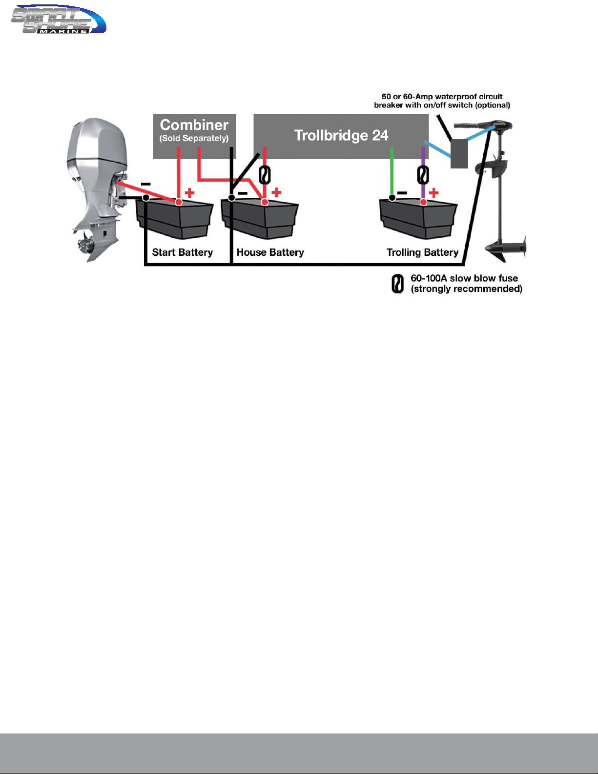
To avoid the risk of melted cables or re you SHOULD install a circuit breaker rated for your motor
(typically 60-Amps or less) on the positive connection to the trolling motor. We also recommend the
installation of a 100-Amp in-line fuse on the red wire from the Trollbridge 24 unit to the positive post on the
starting motor battery (+12V) and a 100-Amp in-line fuse on the purple (or white) wire from the Trollbridge
24 unit to the positive post of the trolling motor battery (+24V). These fuses and circuit breakers will help
to protect against wiring errors during the installation. The recommended fuse holders and replacement
fuses are available to purchase in the Accessories section of our website (SmartShoreMarine.com).
Trollbridge 24
Installation Instructions
Technical Support: 901.382.8888 M-F 8a-5p Central • Tech@SmartShoreMarine.com • SmartShoreMarine.com
© 2023 SmartShore Marine