Zorlu EVC05 Series User manual

User Manual
ELECTRIC VEHICLE CHARGER
EVC05 Series

English - 1IB v3.0.0 2021 © 2021 ZES - All rights reserved
Contents
SAFETY INFORMATION........................................................................................................................2
SAFETY WARNINGS ...........................................................................................................................2
GROUND CONNECTION WARNINGS....................................................................................................3
POWER CABLES, PLUGS and CHARGING CABLE WARNINGS............................................................3
REQUIRED UPSTREAM PROTECTIONS...............................................................................................4
DESCRIPTION......................................................................................................................................5
1 - MODEL DESCRIPTION....................................................................................................5
GENERAL INFORMATION.....................................................................................................................5
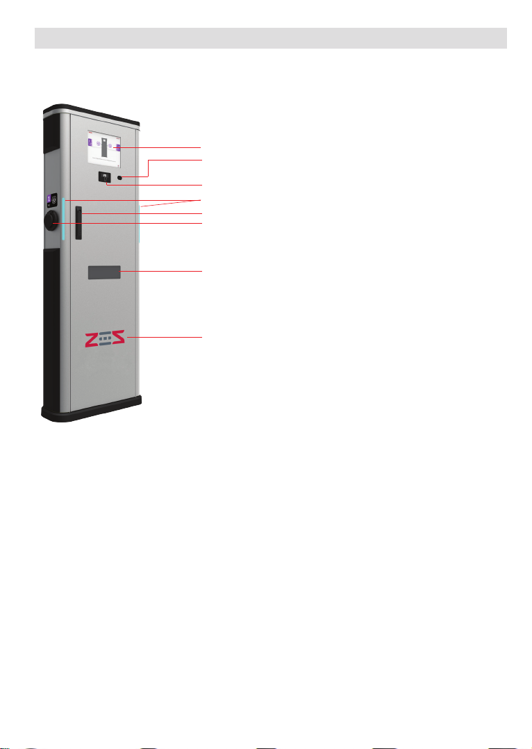
1 - PRODUCT COMPONENTS INTRO ................................................................................5
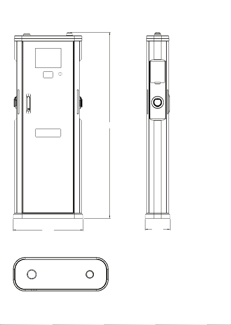
2 - DIMENSIONAL DRAWINGS............................................................................................6
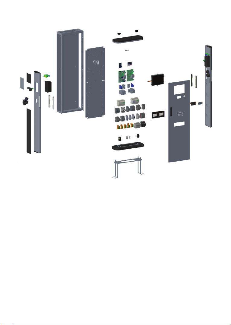
3-ELECTRICVEHICLECHARGINGSTATIONEXPLODED PICTURE..........................................7
REQUIRED EQUIPMENT, TOOLS and ACCESSORIES.........................................................................9
1 - SUPPLIED INSTALLATION EQUIPMENTS and ACCESSORIES......................................9
2 - RECOMMENDED EQUIPMENTS and TOOLS..................................................................9
ELECTRICAL SPECIFICATION...............................................................................................................10
USER INTERFACE & AUTHENTICATION...............................................................................................10
CONNECTIVITY..................................................................................................................................11
MECHANIC SPECIFICATIONS............................................................................................................11
ENVIRONMENTAL TECHNICAL SPECIFICATIONS...........................................................................11
INSTALLING CHARGE STATION........................................................................................................11
1 - UNPACK CHARGING STATION ...................................................................................12
2 - BOX CONTENTS FOR CHARGING STATION................................................................13
3 - FOUNDATION, ALINGMENT & PLACEMENT .............................................................14
4 - OPENING SIDE COVERS ............................................................................................19
5 - CABLE INSTALLATION ..............................................................................................20
5.1 - OPENNING SIDE COVER AND CABLE CONNECTION .............................20
5.2 - SIM CARD CONNECTION ........................................................................23
5.3 - CONNECT OCPP OVER ETHERNET ........................................................23
5.4 - CONNECT PC TO THE SAME NETWORK WITH ETHERNET PORT.........25
5.5 - OPEN WEB CONFIG UI WITH BROWSER...................................................26
5.6 - MAIN PAGE..............................................................................................27
5.7 - MAKE SETTINGS CHANGE IN WEB CONFIG UI......................................28
5.7.1 - GENERAL SETTINGS..............................................................28
5.7.2 - OCPP SETTINGS.....................................................................30
5.7.3 - NETWORK INTERFACES SETTINGS.....................................34
5.7.4 - OCPP CONNECTION SETTINGS............................................35
5.7.5 - SYSTEM MAINTENANCE PAGE ...........................................36
5.8 - CLOSE COVER ........................................................................................40

English - 2© 2021 ZES - All rights reservedIB v3.0.0 2021
SAFETY INFORMATION
CAUTION
RISK OF ELECTRIC SHOCK:
CAUTION: VESTEL ELECTRIC VEHICLE CHARGER DEVICE SHALL BE MOUNTED BY A LICENSED OR
AN EXPERIENCED ELECTRICIAN AS PER ANY REGIONAL OR NATIONAL ELECTRIC REGULATIONS AND
STANDARDS IN EFFECT.
CAUTION
AC grid connection and load planning of the electric vehicle charging device
shall be reviewed and approved by authorities as specified by the regional
or national electric regulations and standards in effect. For multiple electric
vehicle charger installations the load plan shall be established accordingly. The manufacturer shall
not be held liable directly or indirectly for any reason whatsoever in the event
of damages and risks that are borne of errors due to AC grid supply connection or load planning.
IMPORTANT - Please read these instructions fully before installing or operating
SAFETY WARNINGS
• Keep this manual in a safe place. These safety and operating instructions must be kept in a
safe place for future reference.
• Check that the voltage marked on the rating label and do not use charging station without
appropriate mains voltage.
• Do not continue to operate the unit if you are in any doubt about it working normally, or if it
is damaged in any way - switch off the mains supply circuit breakers (MCCB and RCCB) in
upstream distribution panel. Consult your local dealer.
• The ambient temperature range during charging should be between –25 °C and +50 °C (without
direct sunlight) and at a relative humidity of between 5 % and 95 %. Use the charging station
only within these specified operating parameters.
• The device location should be selected to avoid excessive heating of the charging station. High
operating temperature caused by direct sunlight or heating sources, may cause reduction of
charging current or temporary interruption of charging process.
• The charging station is intended for outdoor and indoor use. It can also be used in public places.
• To reduce the risk of fire, electric shock or product damage, do not expose this unit to severe
rain, snow, electrical storm or other severe weathers. Moreover, the charging station shall
not be exposed to spilled or splashed liquids.
• Do not touch end terminals, electric vehicle connector and other hazardous live parts of the
charging station with sharp metallic objects.
• Avoid exposure to heat sources and place the unit away from flammable, explosive, harsh, or
combustible materials, chemicals, or vapors.
• Risk of Explosion. This equipment has internal arcing or sparking parts which should not be
exposed to flammable vapors. It should not be located in a recessed area or below floor level.
• This device is intended only for charging vehicles not requiring ventilation during charging.
• To prevent risk of explosion and electric shock, ensure that the specified Circuit Breaker and
RCD are connected to building grid.

English - 3IB v3.0.0 2021 © 2021 ZES - All rights reserved
• Charging Station bottom must be at (or above) the ground level.
• Adaptors or conversion adapters are not allowed to be used. Cable extension sets are not
allowed to be used.
• The allowed current value of the service socket is maximum 10A.
• This charging station is floor mounted.
WARNING: Never let people (including children) with reduced physical, sensory or men-
tal capabilities or lack of experience and or knowledge use electrical devices unsupervised.
CAUTION: This vehicle charger unit is intended only for charging electric vehicles not
requiring ventilation during charging.
IMPORTANT SAFETY INSTRUCTIONS
Read carefully all the instructions before starting in order ensure properly
installation of the charge point.
Charging station is designed for installation in outdoor and indoor usage. For each of condition,
the station must be installed safely and proper protection should be ensured.
• Charging station should be installed in areas where there is no risk of explosion.
• Charging station should be installed in areas where there is no risk of falling objects around
which may damage the station.
• The installation surface of the station should be withstanded against the physical and
mechanical forces.
• The charging station should not be installed near areas where water or any liquid can penetrate
into the unit.
• Charging station is designed for charging modes in IEC 61851, it should not be used for
anything other than this.
• Do not modify the charging station which will cause rejection of warranty and responsibility
of Vestel.
• Electrical safety regulations should be followed according to the county which the installation
is done.
• There should not be made repairs when the unit is powered.
• Only qualified technician should have access to electrical parts inside the charging station.
• The installation should be checked periodically by qualified and trained technician.
• The station should not be used if the enclosure or charging socket/plug is cracked or damaged.
• The charging station has TYPE 2 AC outlets to be used for mode 3 charging. Also the charging
station has optional schuko socket outlets to be used for mode 1 charging.

English - 4© 2021 ZES - All rights reservedIB v3.0.0 2021
GROUND CONNECTION WARNINGS
• Charging station must be connected to a centrally grounded system. The ground conductor
entering the charging station must be connected to the equipment grounding lug inside the
charger. This should be run with circuit conductors and connected to the equipment grounding
bar or lead on the charging station. Connections to the charging station are the responsibility
of the installer and purchaser.
• To reduce the risk of electrical shock, connect only to properly grounded outlets.
• WARNING : Make sure that during installing and using, the charging station is constantly
and properly grounded.
POWER CABLES, PLUGS and CHARGING CABLE WARNINGS
• Be sure that plugs and sockets are compatible on charging station side.
• A damaged charging cable can cause fire or give you an electric shock. Do not use this product
if the flexible Charging cable or vehicle cable is frayed, has broken insulation, or shows any
other signs of damage.
• Ensure that the charge cable is well positioned thus; it will not be stepped on, tripped over,
or subjected to damage or stress.
• Do not forcefully pull the charge cable or damage it with sharp objects.
• Never touch the power cable/plug or vehicle cable with wet hands as this could cause a short
circuit or electric shock.
• To avoid a risk of fire or electric shock, do not use this device with an extension cable. If the
mains cable or vehicle cable is damaged it must be replaced by the manufacturer, its service
agent, or similarly qualified persons in order to avoid a hazard.
• Use appropriate protection when connecting to the main power distribution cable.
• The charging station is permanently connected.
REQUIRED UPSTREAM PROTECTIONS
• Class-I/B Lightning Protection must be connected to the upstream distribution panel. The
charger contains Class II/C Type Surge Protector Device (SPD)
• MCCB (Thermic Magnetic Adjustable) must be connected to the upstream distribution box.
Model
AC Socket1
AC Socket2
Schuko Socket1
Schuko Socket2
Power Output
Input Max AC
Current
Recommended
Cross Section
for AC Mains
Required
Circuit Breaker
EVC05-AC44 22 22 NA NA 44 kW 64A 25-35
mm2 80A Curve-C
EVC05-
AC44*****S* 22 22 3,7 3,7 51,4 kW 80A 25-35
mm2 100A Curve-C

English - 5IB v3.0.0 2021 © 2021 ZES - All rights reserved
For distances of 50 meters and below, recommended cross section for AC mains can be applicable.
For the distances more than 50 meters, the cable section calculation should be made by the
electrical installer.
When selecting the installation location, take into consideration the minimum space needed for
operat¬ing and maintenance. Note that EVC does not have hinges on the maintanance door!
When installing the unit, respect the minimum distances space for maintenance and safety reasons.
Please comply accordingly to your country specifications.
The next picture shows how it should be installed.
•Donotinstallnearareaswherewaterorfluidscanpenetrateintotheunit.
•Donotinstalltheunitinunstableterrain.
DESCRIPTION
1 - MODEL DESCRIPTION
Model Name
EVC03-DC Series (Name Coding: EVC05-AC****)
EVC05 : Electric Vehicle AC Charger (Mechanical Cabinet 05)
1st Asterisk (*) can include Outlet Quantity and Rated Power
44 : 22kW with dual outlet (3Phase Supply Equipment)
22 : 11kW with dual outlet (3Phase Supply Equipment)
2nd Asterisk (*) can include combinations of the communication module
options:
Blank : Only Ethernet and RFID
W : WiFi module
L : LTE / 3G / 2G module
P : ISO 15118 PLC module
3rd Asterisk (*) can be mentioned for display option
D : 10.4” Display with touchscreen
4rd Asterisk (*) can be mentioned for MID option
M : Charging unit with MID meter
5rd Asterisk (*) can be mentioned for RCCB Reclosure Unit option
Blank : No RCCB Reclosure Unit
R : Charging unit with RCCB Reclosure Unit
6rd Asterisk (*) can be mentioned for Schuko Unit option
Blank : No Schuko Outlet
S : Charging unit with Schuko Outlet
7rd Asterisk (*) can be one of the following:
Blank : Case-B Connection with normal socket
T2S : Case-B Connection with shuttered socket
T2L : Case-B Connection with LID socket
T2P : Case-B Connection with Type-2 socket
Cabinet EVC05

English - 6© 2021 ZES - All rights reservedIB v3.0.0 2021
GENERAL INFORMATION
1 - INTRODUCTION OF THE PRODUCT COMPONENTS
4
6
7
8
5
1
3
2
1- Display
2- ALS Sensor
3- RFID Card Reader
4- Notification LED
5- Door Lock Mechanism
6- AC Type-2 Socket Outlet
7- MID Display Window
8- Branding Area

English - 7IB v3.0.0 2021 © 2021 ZES - All rights reserved
2 - DIMENSIONAL DRAWINGS
Front and Side View
1530
575 205
Top View
Figure.2

English - 8© 2021 ZES - All rights reservedIB v3.0.0 2021
3 - ELECTRIC VEHICLE CHARGING STATION EXPLODED PICTURE
1
2
3
4
5
6
8
9
7
10
14
13
12
15
16
18 19 36
20
22
23
24 25 35
38 39
40
26
27
28
29
37
30
33
34
31 32
21
17
11
Figure-3

English - 9IB v3.0.0 2021 © 2021 ZES - All rights reserved
NO PART DESCRIPTION NUMBER NO PART DESCRIPTION NUMBER
1Access cover for schuko
outlet 2 21 MCT board 2
2 Cosmetic cover 2 22 Contactor 2
3 Schuko socket 2 23 MID 2
4 Type-2 AC socket 2 24 RCCB 2
5 Cosmetic cover 2 25 RCCB reclosure unit 2
6 Side cover 2 26 MCB 2
7Schuko interlock
mechanism 2 27 Power supply 1
8 Schuko housing 2 28 AC bar 5
9 Notification LED 4 29 Surge protection device 1
10 Main body 1 30 SPD fuse box 1
11 Mounting plate 1 31 AC cable gland 2
12 LTE antenna 1 32 Signal cable gland 2
13 WiFi antenna 1 33 Bottom cover 1
14 Top cover 1 34 Anchor set 1
15 WiFi board 1 35 MID display glass 1
16 Ethernet switch board 1 36 HMI & Display 1
17 GSM board 1 37 Front cover 1
18 AC control card 1 1 38 RFID reader 1
19 AC control card 2 1 39 ALS Sensor 1
20 DC 6mA Sensor 2 40 Side cover group 1

English - 10© 2021 ZES - All rights reservedIB v3.0.0 2021
ELECTRICAL SPECIFICATION
IEC Protection class Class - I
Socket Outlet (Vehicle Interface)
IEC 62196 AC Type-2
IEC 62196 Shuttered Socket (optional)
IEC 62196 Locked Cover Socket (optional)
Schuko Socket with Lock Mechanism
(Optional)
Type E
Type F
Cable Outlet (Vehicle Interface) (Optional) Cable with TYPE 2 ( IEC 62196) Female Plug
Voltage & Current Rating 400 VAC 50/60 Hz - 3-Phase 32A
230VAC 50/60 Hz – 1-Phase 16A (For Schuko)
AC Maximum Charging Output
2 x 22kW for AC Socket outlet
2 x 3,7KW for Schuko outlet
Total 51,4KW
Serial Interface Modbus / M-Bus over RS485
Power Level Control WebConfig UI
Built-in DC residual current sensor DC 6 mA
Display Color 10.4” TFT LCD with resistive touchscreen user interface
Built-in MID meter Class B MID meter
Eichrecht conformity (optional)
Built-in RCCB Type-A High Immunity
RCCB Reclosing Unit Optional
Built-in MCB 40A Type C for AC outlets, 20A Type C for Schuko outlets
EV Ready, ZE Ready Optional
Surge Protection Device Yes
Built-in Electrical Protection
Over Current, Over Voltage, Under Voltage, DC/AC Residual
Current, Over Temperature, Short Circuit, Socket Interlo-
ck, Surge/Lightning, Earth Fault, Phase- Neutral Reverse
Detection
CONNECTIVITY
Ethernet 100 Mbps Ethernet (Standard with M / W / L / P options)
Daisy Chain
Wi-Fi 802.11 a/b/g/n
Mobile Connectivity (Optional) LTE / 3G / 2G
PLC HLC (Optional) ISO 15118
RFID Reader ISO 14443A/B and ISO 15693 w/SAM Module

English - 11IB v3.0.0 2021 © 2021 ZES - All rights reserved
OTHER FEATURES (Connected Models)
Remote Diagnostics Remote Diagnostics over OCPP
OCPP OCPP 1.6
Load Management Ethernet / Wi-Fi / RS485
OCPP Smart Charging
MultiCP Local Load Balancing
Software Update Remote software update over OCPP
Local software update via USB port
USB port (internal) USB 2.0
Sensors ALS, Tilt Sensor
MECHANICAL SPECIFICATIONS
Material Metal Panel
Protection Degree Ingress Protection
Impact Protection
IP54
IK10 (In screen and sockets IK08)
Dimensions 1530.0 mm (Height) x 575.0 mm (Width) x 205.0 mm (Depth)
Dimensions (with packing) 1600.0 mm (Height) x 800.0 mm (Width) x 400.0 mm (Depth)
AC Mains Cable Dimension &
Cable Gland Diameters
For 16mm2-35mm2 AC Mains, suitable cable gland diameter interval is
22mm-32mm
Weight 85 kg
Weight (with packing) 95 kg
ENVIRONMENTAL SPECIFICATIONS
Operation Condition Temperature
Humidity
Altitude
-25 °C to + 50 °C
5 % - 95 % (Relative humidity, non-condensing)
0-3.000m

English - 12© 2021 ZES - All rights reservedIB v3.0.0 2021
REQUIRED EQUIPMENT, TOOLS and ACCESSORIES
1. REQUIRED EQUIPMENT, TOOLS and ACCESSORIES
1.1 SUPPLIED INSTALLATION EQUIPMENTS and ACCESSORIES
1 set (x2) Lock Keys
Steel Expansion Bolts 10x80mm (4 units)
M12 anchor special bolt set (4 units)
Anchor plate (1 unit)
Artwork Kit (User and Installation Manuels)
UserManual
ELECTRICVEHICLE CHARGER
EVC05Series
UserManual
ELECTRICVEHICLE CHARGER
EVC05Series
User RFID Card (2 Units)
MASTER
1.2 RECOMMENDED EQUIPMENTS and TOOLS
Ø20 Drill Bit Impact Drill PC
Philips Screwdriver RJ45 Crimping Tool Cat5e or cat6 ethernet cable
Spanner set Hammer Level Indicator Ruler
Adjustable Wrench
(0-50mm) Allen set

English - 13IB v3.0.0 2021 © 2021 ZES - All rights reserved
2. BEFORE INSTALLATION
REQUIRED UPSTREAM PROTECTIONS
• Class-I/B Lightning Protection must be connected to the upstream distribution panel. The
charger contains Class II/C Type Surge Protector Device (SPD)
• MCCB (Thermic Magnetic Adjustable) must be connected to the upstream distribution box.
Model
AC Socket1
AC Socket2
Schuko Socket1
Schuko Socket2
Power Output
Input Max AC
Current
Recommended
Cross Section
for AC Mains
Required
Circuit Breaker
EVC05-AC44 22 22 NA NA 44 kW 64A 25-35 mm2 80A Curve-C
EVC05-
AC44*****S* 22 22 3,7 3,7 51,4 kW 80A 25-35 mm2 100A Curve-C
For distances of 50 meters and below, recommended cross section for AC mains can be applicable.
For the distances more than 50 meters, the cable section calculation should be made by the
electrical installer.
When selecting the installation location, take into consideration the minimum space needed for
operat¬ing and maintenance. Note that EVC does not have hinges on the maintanance door!
When installing the unit, respect the minimum distances space for maintenance and safety reasons.
Please comply accordingly to your country specifications.
The next picture shows how it should be installed.
•Donotinstallnearareaswherewateroruidscanpenetrateintotheunit.
•Donotinstalltheunitinunstableterrain.

English - 14© 2021 ZES - All rights reservedIB v3.0.0 2021
Minimum 500mm in two sides, 200mm from back side, it is recommended to have space around
the charging station. Also to open the front cover completely, it is needed to have minimum 500mm
of space in front of the station.
It is also recommended to place a mechanical barrier in front of the charger against the vehicle
hits or etc. Between the charging station and this barrier, minimum 500mm is needed.
500mm
500mm
500mm
200mm
3. INSTALLING CHARGING STATION
Screws inside the product are recommended to be exceeding 240 hours Salt Fog test under ASTM
B117 Method. Screws outside the product are recommended to be exceeding 720 hours.
WARNING: RISK OF ELECTRICAL SHOCK AND INJURY. POWER OFF THE CHARGING
STATION MAIN SUPPLY BEFORE ANY INSTALLATION STEPS
WARNING: TO AVOID PERSONAL INJURY OR DAMAGE THE CHARGING STATION, ENSURE THE
INSTALLATION AREA IS SUITABLE AND THE FLOOR CAN WITHSTAND THE WEIGHT OF THE CHARGING
STATION.

English - 15IB v3.0.0 2021 © 2021 ZES - All rights reserved
3.1 UNPACK CHARGING STATION
1- Remove the ropes and films around the package.
2- Remove the carton box upwards.
3- Take supplied equipments from the box.
4- Remove the epees one by one upwards.
5- The station is assembled with bottom part and the palette in production, to be able to carry the
station to the installation area easily.
1 2
3 4 5

English - 16© 2021 ZES - All rights reservedIB v3.0.0 2021
3.2 - OPENING THE FRONT COVER
Use the key provided to unlock the front cover. Pull the handle slightly up. Turn the handle through
the back side of the charging station with wide-angle.
12
3
3.3 - REMOVING THE BOTTOM PART OF CHARGING STATION FROM THE
PALETTE
1- Disassemble the M10x30 imbus screws from the bottom part of the charging stations by with
8 allen as shown in figure.
2- Remove the bottom part and the pallet from the charging station.
3- Remove the metal plates under the pallette as shown in figure.
4- Remove the pallette and bottom cover to start the installing of bottom part to the available
surface.
1 1
2
3 4

English - 17IB v3.0.0 2021 © 2021 ZES - All rights reserved
You can install and mount the charging station to the ground with 2 available solutions. By prepar-
ing the concrete/anshor plate and second option is to position the charger over the ready concrete
(cabling should be ready before).
3.4 - INSTALLING THE STATION BY PREPARING THE CONCRETE AND ANCHOR
PLATE
Make sure that the materials used for the concrete foundation and the installation procedures
follow local building regulations and safety standards.
For Preparing and Mounting the Anchor Plate, below three steps should be followed as also
shown in figures:
1- Insert each nut to each bolt one by one as shown in figure.
2- Insert the anchor plate to the bolts as shown in figure.
3- Assemble the nuts over the anchor bolt to fix it with the bolts.
1 2 3
For Preparing Installation area and cabling, below steps should be followed as also shown in
figures:
1- Dig a pit (dimensions 200x580x300 – DxWxH in mm) for anchor bolts and plate assembly. The
pitoorshouldbetrampledandhorizontal
2- Place anchor assembly in the pit.
3- Cables must be placed in the middle and should be pulled through the plate hole, before con-
crete applied. Pull the supply cable and possible data cable through the ground mounting box
cable gland(s) and further through the mounting box cable hole. For AC mains cable minimum
500 mm, for ethernet cable minimum 2 meters from the ground surface of the mounting box
should be left.
4- Fill the pit with concrete. Then adjust the assembly as seen in the picture. 2nd bolt top surface
must be on the ground level. Level indicator ruler can be used while adjusting.
5- Let the concrete solidify, make sure the surface stays solid and level during the process.
6- Put the bottom part of the charging station over the anchor plate as shown in figure. Put in the
cables from the middle of the bottom cover.
7- Assemble the metal holes and nuts over the bottom cover and fix it to the surface, as shown
in figure.

English - 18© 2021 ZES - All rights reservedIB v3.0.0 2021
8- Position and mount the charging station over the bottom cover by re-assembling 4 pieces of
M10x30 imbus screws which were disassembled in the beginning of installation as shown in
figure.
3 4
12
300
500
200

English - 19IB v3.0.0 2021 © 2021 ZES - All rights reserved
5 6
7 8
This manual suits for next models
2
Table of contents
Popular Batteries Charger manuals by other brands

Webasto
Webasto SVS100 Installation, operation and maintenance manual

ROLEC
ROLEC BasicCharge ROLEC0211B Installation & operation manual

Duracell
Duracell DRMC4A manual

xtorm
xtorm XW204 user manual

Teledyne Battery Products
Teledyne Battery Products GC-012 operating instructions

Victron energy
Victron energy Blue Power 12/15 manual