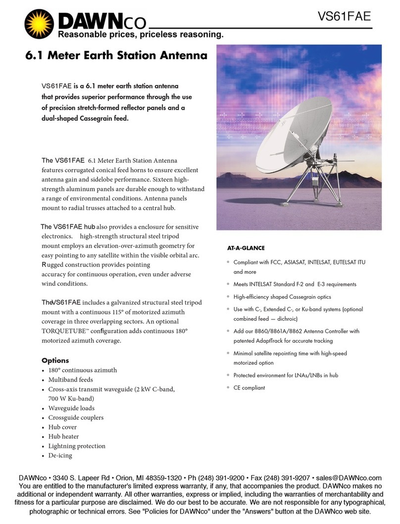
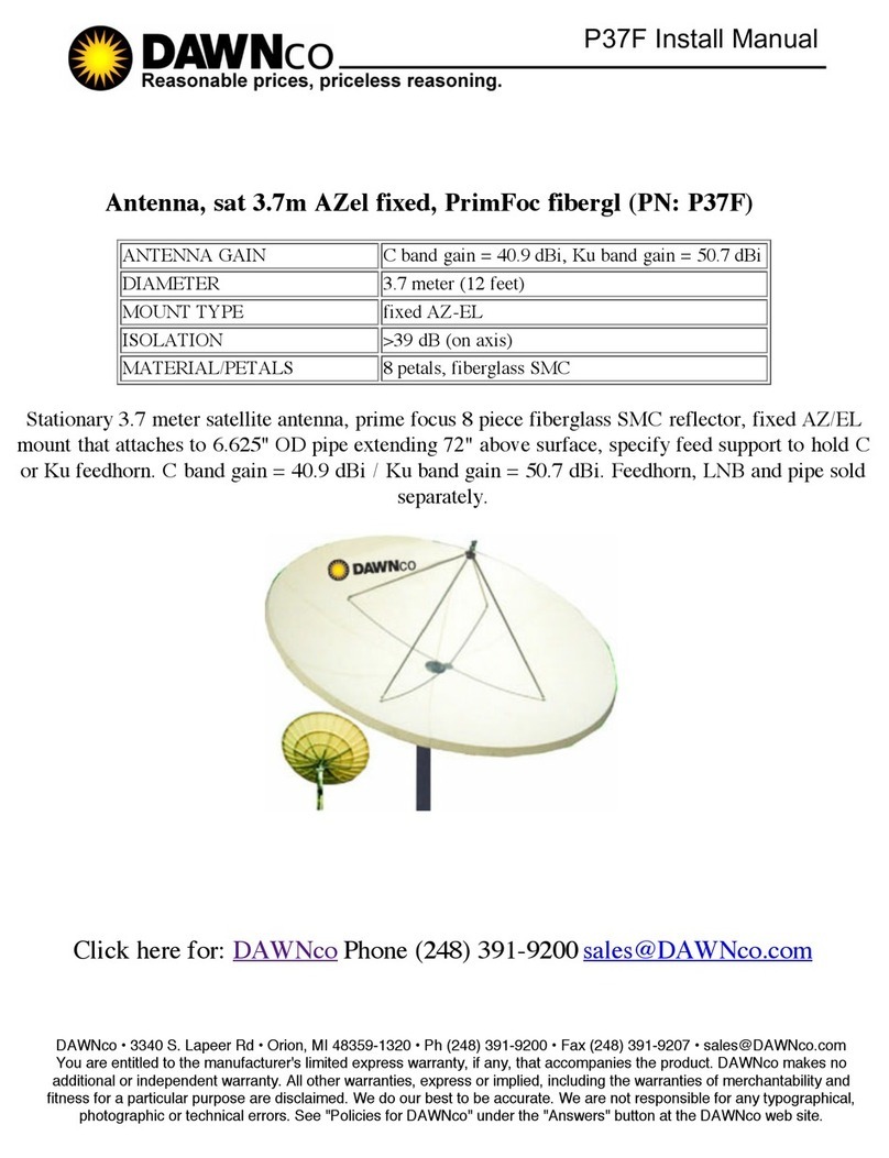
Dawnco 1252 Series User manual

Option
C-Band Feed
Back View
Series 1253
2.4M
C & KU-BAND
RECEIVE ONLY
Key Features
· Precision compression
molded centerfed reflector
· Series 1252 - Az/El Mount
· Series 1253 - Polar mount
· Low transportation cost with
three panel reflector
· Individual panels inter-
changeable and field
replaceable
· Galvanized steel mounts
Manufactured by the
world’slargestmanufacturerof
Rx/TxVSATantennas. Wehave
the broadest product line in the
industry including Receive Only,
Rx/TxandRuralTelephony
antennasystems.
Nineteenantennasizes, 47cm to
4.5M. Manufacturer is the leader in
obtainingtypecertificationsand
approvalsforIntelsat, AsiaSat
and Eutelsat. The antennas
provide the best quality in the
marketdue to thesophisticated,
precision SMC compression
molding process technology.
Provides the best value
antennasolution to the market
withcompetitiveprices, the
highest quality products and
superb engineering support.
P24F
DAWNco • 3340 S. Lapeer Rd • Orion, MI 48359-1320 • Ph (248) 391-9200 • Fax (248) 391-9207 • [email protected]
You are entitled to the manufacturer's limited express warranty, if any, that accompanies the product. DAWNco makes no
additional or independent warranty. All other warranties, express or implied, including the warranties of merchantability and
fitness for a particular purpose are disclaimed. We do our best to be accurate. We are not responsible for any typographical,
photographic or technical errors. See "Policies for DAWNco" under the "Answers" button at the DAWNco web site.

EnvironmentalPerformance
Receive Only
Series 1252 & 1253
Mechanical
2.4M
C & KU-BAND
RECEIVE ONLY
SERIES
1252 & 1253
Series 1252 & Series 1253
C-Band Ku-Band
AntennaSize 2.4M(96in.) 2.4M(96in.)
OperatingFrequency(GHz) 3.625-4.2 GHz 10.95-12.75GHz
MidbandGain(+.2dB) 37.5dBi 47.0dBi
3dBBeamwidth 2.1° .7°
AntennaNoiseTemperature(normal)
20°elevation 33 K 29 K
30°elevation 31 K 28 K
FeedInterface CPR 229 F WR75
Cross-PolIsolation(Linear) >30 dB(on axis) >30dB (onaxis)
FirstSidelobe(typical) -20 dB -20 dB
InsertionLoss 0.2 dB Max. 0.2 dB Max.
VSWR 1.3:1 Max. 1.3:1 Max.
ReflectorMaterial ThreeSegmentGlassFiberReinforcedPolyesterSMC
AntennaOptics Prime Focus, Axisymmetric
Mast PipeSize 5" SCH 40 Pipe (5.56" OD) 14.13 mm.
ElevationAdjustmentRange 0°to90°ContinuousFineAdjustment
AzimuthAdjustmentRange +45°Fine,360°Continuous
f/DRatio/FeedSupport .37/TripodFeedSupport
DeclinationCorrectedPolarRange 90°ArcCoverage with24”Actuator,Available
ShippingSpecifications(Weight) Az/El: 205 lbs. (93 kg.) Polar: 245lbs.(111 kg.)
WindLoading Operational 50mph(80km/h)
Survival 125mph(201km/h)
Temperature Operational -40°to140°F(-40°to60°C)
Survival -50°to160°F(-46°to71°C)
Rain Operational 1/2"/hr
Survival 2"/hr
Ice Operational --------
Survival 1/2"radial
AtmosphericConditions Salt,PollutantsandContaminantsas
EncounteredinCoastalandIndustrialAreas
SolarRadiation 360BTU/h/ft2
P24F
DAWNco • 3340 S. Lapeer Rd • Orion, MI 48359-1320 • Ph (248) 391-9200 • Fax (248) 391-9207 • [email protected]
You are entitled to the manufacturer's limited express warranty, if any, that accompanies the product. DAWNco makes no
additional or independent warranty. All other warranties, express or implied, including the warranties of merchantability and
fitness for a particular purpose are disclaimed. We do our best to be accurate. We are not responsible for any typographical,
photographic or technical errors. See "Policies for DAWNco" under the "Answers" button at the DAWNco web site.

4096-356
REVISION C
January 11, 2002
Assembly Manual
2.4Meter Series 1252
Az/El Truss Mount
P24F
DAWNco • 3340 S. Lapeer Rd • Orion, MI 48359-1320 • Ph (248) 391-9200 • Fax (248) 391-9207 • [email protected]
You are entitled to the manufacturer's limited express warranty, if any, that accompanies the product. DAWNco makes no
additional or independent warranty. All other warranties, express or implied, including the warranties of merchantability and
fitness for a particular purpose are disclaimed. We do our best to be accurate. We are not responsible for any typographical,
photographic or technical errors. See "Policies for DAWNco" under the "Answers" button at the DAWNco web site.

2.4M Series 1252
Az/El Truss Mount
C Revised Address 1/11/02 RAH
B Revised text on pages 22 & 23 04/06/99 RAH
A Redesign & update manual 07/21/98 PGW
- ORIGINAL RELEASE 11/23/94 R FRYE
REV. DESCRIPTION DATE APPROVED
P24F
DAWNco • 3340 S. Lapeer Rd • Orion, MI 48359-1320 • Ph (248) 391-9200 • Fax (248) 391-9207 • [email protected]
You are entitled to the manufacturer's limited express warranty, if any, that accompanies the product. DAWNco makes no
additional or independent warranty. All other warranties, express or implied, including the warranties of merchantability and
fitness for a particular purpose are disclaimed. We do our best to be accurate. We are not responsible for any typographical,
photographic or technical errors. See "Policies for DAWNco" under the "Answers" button at the DAWNco web site.

4096-356
DAWNco satellite products 2.4M Az/El TRUSS MOUNT
3

4096-356
DAWNco satellite products 2.4M Az/El TRUSS MOUNT
4
ASSEMBLY MANUAL
Table Of Contents
Section Title
1.0 General Information
1.1 Unpacking & Inspection
1.2 Mechanical Installation Tools
1.3 Site Selection
1.4 Foundation Requirements
2.0 Reflector And Support Structure Assembly
2.1 Reflector and Support Structure Part List
2.2 Reflector Pre- Assembly
2.3 Reflector Assembly
2.4 Support Structure Assembly
3.0 Reflector Installation
3.1 Reflector Mount Part List
3.2 Canister / Elevation Rod Assembly
3.3 Reflector Positioning
4.0 Feed Installation
4.1 Feed Horn Assembly
4.2 Feed System Part List
4.3 Feed Support Assembly
4.4 Feed Installation
4.5 Feed Cover Installation
5.0 Antenna Alignment And Tuning
5.1 Elevation Adjustment
5.2 Azimuth Adjustment
5.3 Fine Tuning
5.4 Reflector Fine Adjustment

4096-356
DAWNco satellite products 2.4M Az/El TRUSS MOUNT
5
SECTION 1 GENERAL INFORMATION
1.1 UNPACKING AND INSPECTION
1. UNPACKING & INSPECTION - The antenna containers should be
unpacked and inspected at the earliest date to ensure that all material has
been received and is in good condition. A complete packing list for each
major component is supplied.
2. FREIGHT DAMAGE - Any damage to materials while in transit should be
immediately directed to the freight carrier. He will instruct you on the
matters regarding any freight damage claims.
3. MATERIAL - MISSING OR DAMAGED - Any questions regarding missing
or damaged materials that is not due to freight carrier should be directed
to Prodelin's Customer Service Department at:

4096-356
DAWNco satellite products 2.4M Az/El TRUSS MOUNT
6
1.2 MECHANICAL INSTALLATION TOOLS
HARDWARE SIZE SAE WRENCH
SIZE
METRIC WRENCH
SIZE
MAXIMUM REC.
TORQUE
# 6 SCREW 5/16” 8 mm 8 in-lbs
1 / 4” 7 / 16” 11 mm 49 in-lbs
3 / 8” 9 / 16” 14 mm 15 ft-lbs
1 / 2” 3 / 4” 20 mm 35 ft-lbs
5 / 8” 15 / 16” 24 mm 70 ft-lbs
3 / 4” 1- 1 /8” 28 mm 220 ft-lbs
Also recommended for installation:
Adjustable Wrench 10”
Ratchet ( 3 / 8” drive)
Inclinometer
Compass
8’ ft Ladder
Gloves
1.3 SITE SELECTION
In order to achieve maximum performance of your antenna system, it is
important to select the correct location for the antenna. The following guidelines
should be observed when selecting a site for the installation.
1. The line of site to the satellite should be clear of any obstructions, such as
trees or buildings.
2. The site should be relatively flat and level for ease of installation and
access to the antenna.
3. The site should be checked for underground obstruction, such as buried
cables or pipes.
4. All local building codes should be adhered to (i.e. grounding, foundation
requirements, zoning rules, setbacks, etc.).
1.4 FOUNDATION REQUIREMENTS

4096-356
DAWNco satellite products 2.4M Az/El TRUSS MOUNT
7
Prodelin's recommended foundation for the antenna system is shown in figure 1.
however, each installation must be tailored to the specific requirements of the
site. It may be necessary to contact a local engineer or building department for
foundation design or approval at any particular site.
FIGURE 1.
NOTES:
1. 2 x 2 x 1/4 HRS Angle and schedule 40 pipe should conform with ASTM A36 and ASTM A53 Type E and
S Grade B.
2. All concrete should conform to building code standards and have a
minimum compressive strength of 3000 PSI at 28 days. (Per ACI-318-77)
3. Soil bearing capacity should be no less than 2000 PSF.
4-. Concrete should be poured against undisturbed soil.
5. Allow concrete 24 hours set time before installation of antenna.
6. The antenna should be properly grounded to meet applicable local codes.
7. Minimum depth as shown or extend to local frost line.
PRODELIN CORPORATION DOES NOT REPRESENT OR WARRANT THAT ANY PARTICULAR DESIGN
OR SIZE OF FOUNDATION IS APPROPRIATE FOR ANY LOCALITY OR EARTH STATION INSTALLATION
SECTION 2 REFLECTOR AND SUPPORT STRUCTURE ASSEMBLY
24.0
54.0
54.0
See Note #7
SECTION A-A
AA
5 “ SCH 40 PIPE
2 x 2 x 1 / 4 HRS ANGLE
12 INCHES LONG
TYP 2 PL
2-5
TYP 2

4096-356
DAWNco satellite products 2.4M Az/El TRUSS MOUNT
8
REFLECTOR AND SUPPORT STRUCTURE PARTS LIST TABLE 2.1
ITEM PART NO. DESCRIPTION QTY
1 0179-173 REFLECTOR PETAL 3
2 0217-072 FEED SUPPORT CLEVIS 3
3 0490-501 CENTER HUB 1
4 0156-808 CENTER PLATE 1
5 0225-553 ANGLE BRACE 6
6 8104-007
6
7 8201-043
6
8 8202-043
6
PARTS LIST - CONTINUED
ITEM PART NO. DESCRIPTION QTY
1 / 2” HEX NUT
1 / 2” LOCKWASHER
1 / 2” FLATWASHER

4096-356
DAWNco satellite products 2.4M Az/El TRUSS MOUNT
9
9 8030-010
6
10 8201-040
6
11 8202-040
6
12 8032-010
24
13 8201-042
48
14 8202-042
24
15 8102-007
24
NOTE: Assembly of the reflector should be on as level a surface as possible
to prevent warping or misalignment of the reflectors parabolic shape during
assembly. Any loss of contour may affect the antennas signal quality. If a
level surface is not available, refer to section 5.4 for tips on how to check the
3 / 8” HEX NUT
1 / 4” - 20 x 1.25 BOLT
1 / 4” FLATWASHER
1 / 4” LOCKWASHER
3 /8” -16 x 1.25 BOLT
3 / 8” FLATWASHER
3 / 8” LOCKWASHER

4096-356
DAWNco satellite products 2.4M Az/El TRUSS MOUNT
10
reflector shape and correct it if necessary.
2.2 REFLECTOR PRE-ASSEMBLY
The reflector consists of three interchangeable petals of compression molded
glass-fiber reinforced material. This material is very strong, yet lightweight and
easy to handle. The reflector will possess a very accurate parabolic shape when
properly assembled and will retain it’s shape for years under harsh
environmental conditions. The microwave reflective surface is provided by a fine
mesh screen that lies just beneath the molded surface of the petals.
A)
Identify the reflector petals and parts of
the reflector support structure according
to the parts list.
B) Note that the petals (item 1) have a 1 / 2”
hole thru the center. These holes are for the
feed clevises. Pre assemble these three
petals as follows.
C) Run the 1 / 2” nut (item 6) up the threads
of the clevis (item 2), and place a 1 / 2”
flatwasher (item 7) against the nut. Adjust
the nut until the distance from the far side
of the washer and the center of the clevis
is 1.5” .
D) From the face of the petal, insert the clevis
assembly thru the hole in the center of the
petal. Secure with 1 / 2” hardware.
Tighten these nuts hand tight at this time.
1.5
[ 2 ]
[ 6, 7 ] [ 6, 7, 8 ]
[ 1 ]

4096-356
DAWNco satellite products 2.4M Az/El TRUSS MOUNT
11
2.3 REFLECTOR ASSEMBLY
STEP 1:
STEP 2:
Place two petals rim down on a level
surface with their flanges next to
each
other. The petals are free standing
with the rim down and the center up.
E
D
C
B
A
[ 12 ]
[ 13 ]
A)
Begin the assembly at the flange
with 3 / 8” hardware (items 12, 13,
14, 15), in holes A, B, D, and E
only.
B) You may notice that the hardware
fits snugly in the holes. This is to
assure the accurate alignment of
the petals. If necessary, gently tap
or thread the bolts into the holes.
The hardware may now be fully
tightened at this point.
Alignment Tabs
[ 13, 14, 15 ]

4096-356
DAWNco satellite products 2.4M Az/El TRUSS MOUNT
12
STEP 4:
A)
Continue assembling the two petals
as above. Before installing the last
petal, place the center plate (item 4)
beneath the center of the reflector and
attach the center hub (item 3) on top
with 1 / 4”
hardware (items 9, 10, 11). Leave
hardware loose enough to rotate hub.
B) Place the last petal in position, insuring
that the lip on its inner edge is located
between the center hub and plate.
Attach this petal to the adjacent petal
at holes A and B. At this time, the
reflector is strong enough to sustain
the weight of the installer to place the
bolts in holes D & E. Remember not to
insert bolts in hole C as those will be
taken care of in the next section. Be
sure to step only on the ribs, not on the
surface in between.
C) Now tighten all reflector bolts. Before
tightening, check to be sure that all the
petals are aligned properly. It may be
necessary to adjust one petal in or out
(radially) until the rim is flush. Also
check up and down alignment. It is
possible to lift the reflector slightly to
feel the front surface, making sure that
it is flush. Tighten all A bolts first. Next
tighten all B bolts, then D and E.
Note: Before tightening the last set of
reflector bolts, the ones closest to the
hub, check to make sure that the lip on
the inner edges of all petals are located
between the center plate and the center
hub plate.
[9, 10, 11]
[ 3 ]
[ 4 ]
Petal
See Detail
Below

4096-356
DAWNco satellite products 2.4M Az/El TRUSS MOUNT
13
2.4 SUPPORT STRUCTURE ASSEMBLY
STEP 1:
STEP 2:
Attach one of the angle braces (item 5)
to the top of the hub ring as shown.
Note that the notched end of the angle
goes towards the reflector rib. Secure
the angle to the hub with 3/8" hardware
(items 12, 13, 14, 15).
Hub Ring
Center Hub
[ 13, 14, 15 ]
[ 12, 13 ]
[ 5 ]
A)
Rotate the hub if necessary to position
the angle next to the reflector rib at hole
location C as shown.
B) Attach brace with 3 / 8” hardware
(items 12, 13, 14, 15). Do not tighten
until instructed.
C) Attach the remaining 5 angle braces from
the hub ring to the petal ribs in the same
manner.
D) Tighten all hardware completely,
including
the six 1/4" bolts at the base of the
reflector center hub.
Angle Brace
[12, 13 ]
[ 13, 14, 15 ]
Reflector petal

4096-356
DAWNco satellite products 2.4M Az/El TRUSS MOUNT
14
SECTION 3 REFLECTOR INSTALLATION
REFLECTOR MOUNT PARTS LIST TABLE 3.1
ITEM PART NO. DESCRIPTION QTY
1 0490-502 CANISTER 1
2 0168-085 ELEVATION ADJUSTMENT BLOCK 1
3 0490-476 ELEVATION ADJUSTMENT ROD 1
4 8317-105 5/8" x 2.00 SQ. HD BOLT 6
5 8033-010
2
6 8033-024
1
8201-030
4
8 8202-043
3
1/2" LOCKWASHER
1/2" FLATWASHER
1/2" x 1.25 BOLT
1/2" x 3.00 BOLT
7

4096-356
DAWNco satellite products 2.4M Az/El TRUSS MOUNT
15
PARTS LIST - CONTINUED
ITEM PART NO. DESCRIPTION QTY
9 8104-007
1
10 8036-048 1" X 6.00 BOLT 1
11 8202-046
1
12 8107-007
1
13 8105-007
2
14
8201-046 1” FLATWASHER 2
1/2" HEX NUT
5/8" HEX NUT
1" HEX NUT
1" LOCKWASHER
DAWNco • 3340 S. Lapeer Rd • Orion, MI 48359-1320 • Ph (248) 391-9200 • Fax (248) 391-9207 • [email protected]

4096-356
DAWNco satellite products 2.4M Az/El TRUSS MOUNT
16
NOTE: At least three persons are required for the installation of the antenna on
the mast. After the reflector is positioned on the canister, two can steady the
reflector while the other secures it with the 1" bolt.
3.2 CANISTER & ELEVATION ASSEMBLY
STEP 1:
STEP 2:
STEP3:
Assemble the elevation rod by running
5/8" nut (item 13) well up onto the
elevation rod (item 3). Slip the
elevation
block ( item 2) onto the rod and secure
with another 5/8" nut.
Insert each square head bolt (item 4 )
into the canister, only a few turns, so
that the bolts do not extend into the
canister. Position the canister on the
mast and insure that it is seated all the
way down on the mast pipe and that it
can rotate freely.
Canister
[ 4 ]
6 PL
Mast
Place the elevation rod assembly in
between the two tabs on the canister
and secure with 3/8" hardware ( items
5, 7, 8 ).
[ 3 ]
[ 13 ]
[ 2 ]
[ 13 ]
[ 5, 7, 8 ]
[ 5, 7, 8 ]

4096-356
DAWNco satellite products 2.4M Az/El TRUSS MOUNT
17
3.3 REFLECTOR POSITIONING
STEP 1:
Bring the completed reflector assembly
to the pedestal and locate it about 1-1/2
to 2 feet away from the mast. Make sure
that the elevation brackets on the hub
are pointing away from the mast. Use
the reflector carton (or similar object) as
a rest for under the edge of the
reflector.
Be sure to have the 1" hardware close
at hand ( items10, 11, 12 ).
Mast
Carton
Canister
Reflector Assembly
Elevation Brackets
on the Center Hub
[ 5, 7, 8 ]

4096-356
DAWNco satellite products 2.4M Az/El TRUSS MOUNT
18
STEP 2:
STEP 3:
SECTION 4 FEED INSTALLATION
4.1 FEED HORN ASSEMBLY
Swing the reflector up until the hub can
be placed in between the top brackets
the canister. With the holes aligned,
secure the reflector with 1" hardware
( items 10, 11, 12 ).
Center Hub
[ 10 ]
Raise or lower the reflector until you can
place the tube of the elevation adjustment
rod in between the two tabs on the center
hub. Secure in place with 1/2" hardware
( items 6, 7, 8, 9 ). Do not tighten these
bolts until section 5.1.
[ 6, 7 ]
[ 7, 8, 9 ]
Elevation Tabs
Elevation Rod
[ 11, 12, 14 ]
Canister
This manual suits for next models
1
Table of contents
Other Dawnco Antenna manuals
Popular Antenna manuals by other brands
Codan
Codan 3048 Installation handbook
Taoglas
Taoglas MA114 Series installation instructions
Parsec Technologies
Parsec Technologies Beagle G installation instructions

Kathrein
Kathrein CAS 90ws/HD manual
Directive Systems & Engineering
Directive Systems & Engineering DSE3319LYK quick start guide

Spiderbeam
Spiderbeam 160-18-4WTH Construction guide
