Shively Labs 6600 User manual

Horizontally Polarized FM
Broadcast Antenna
Model 6600
Instruction Manual
Installation, Operation, &
Maintenance

2
Congratulations! Thank you for purchasing one of the finest FM broadcast antennas on the
market today. The Shively Labs Model 6600 is widely recognized as the top-of-
the-line in its class for its superior performance and durability.
Your purchase is backed by the best technical support in the industry. Shively
is a leading manufacturer in the broadcast industry, providing an extensive
range of antennas, transmission line and components. Our technical staff has
a wealth of experience in the broadcast industry and is standing by to serve
you in any way.
This manual is intended to give you a good basic understanding of your
antenna: its proper and safe installation, startup, and operation, and trouble-
shooting and maintenance information to keep it working satisfactorily for
years to come.
Please have everyone involved with the antenna read this
manual carefully, and keep it handy for future reference.
Meanwhile, please feel free to contact your sales representative at Shively
Labs at any time if you need information or help. Call or write:
Publication No. im-6600 (150520)

IMPORTANT
Please read this manual in its entirety before beginning
installation of your antenna!
Failure to follow the installation and operation
instructions in this manual could lead to failure of your
equipment and might even void your warranty!


i
Table of Contents
Chapter 1 Preparing for Installation..................................................1
Receiving..............................................................................................1
Unpacking ............................................................................................1
Check the System .................................................................................1
Chapter 2 Installing the Radiators.....................................................3
Before Beginning Radiator Installation:...................................................3
Installation Procedure............................................................................3
Figure 1 Baymount Detail................................................................ 4
Figure 2 Radiator Installation, exploded view.................................... 4
Figure 3 Flange Bolt Tightening Sequences ...................................... 5
Table 1 Torque Specifications, Flange Bolts...................................... 5
Chapter 3 Installing the Radomes (if applicable)..............................7
Before Beginning Radome Installation: ...................................................7
Installation of Radomes.........................................................................7
Figure 4 Radome Installation........................................................... 7
Chapter 4 Installing Feedline and Transformer ................................9
Before Beginning Feedline and Transformer Installation:..........................9
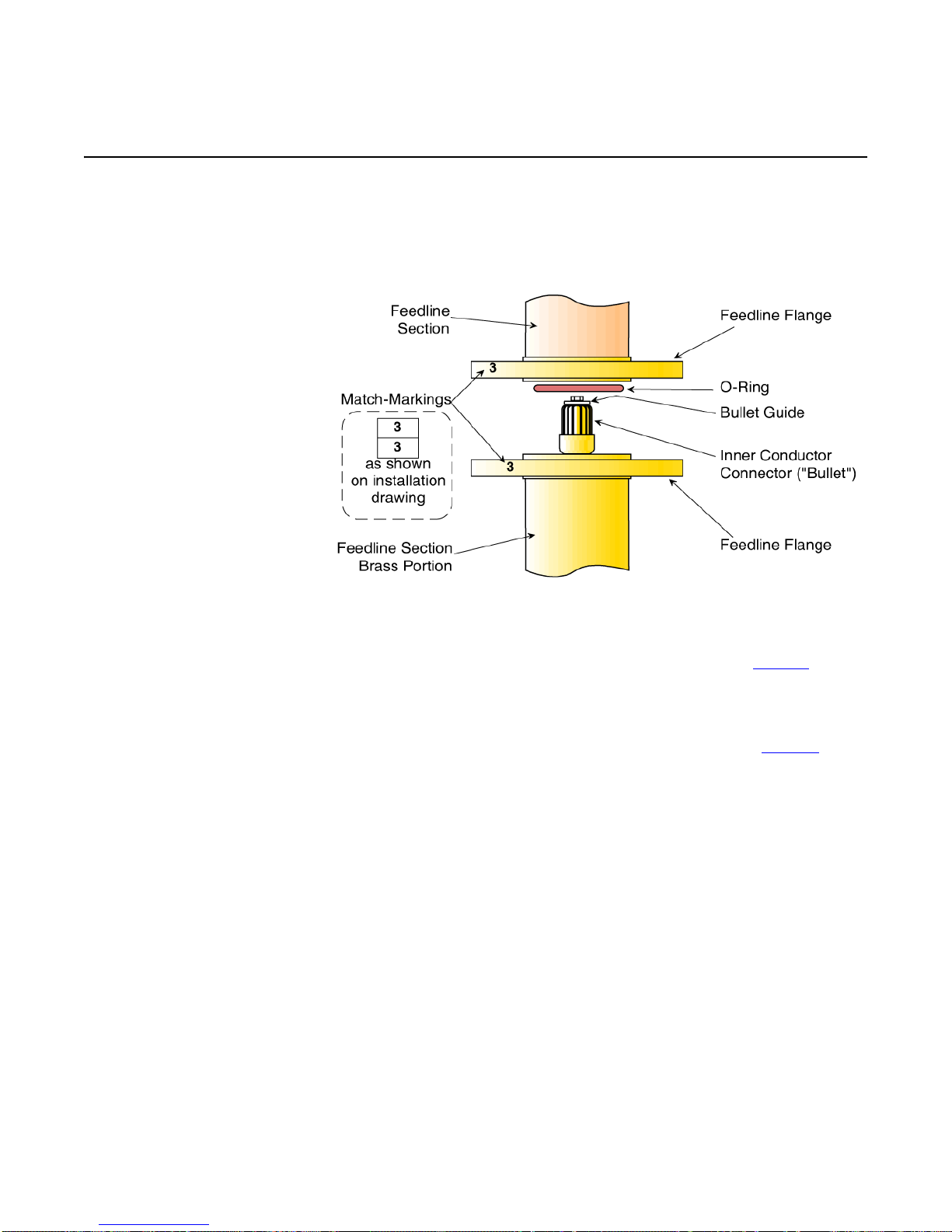
Figure 5 Feedline Flange Detail........................................................9
Installing the Feedline Mounts..............................................................10
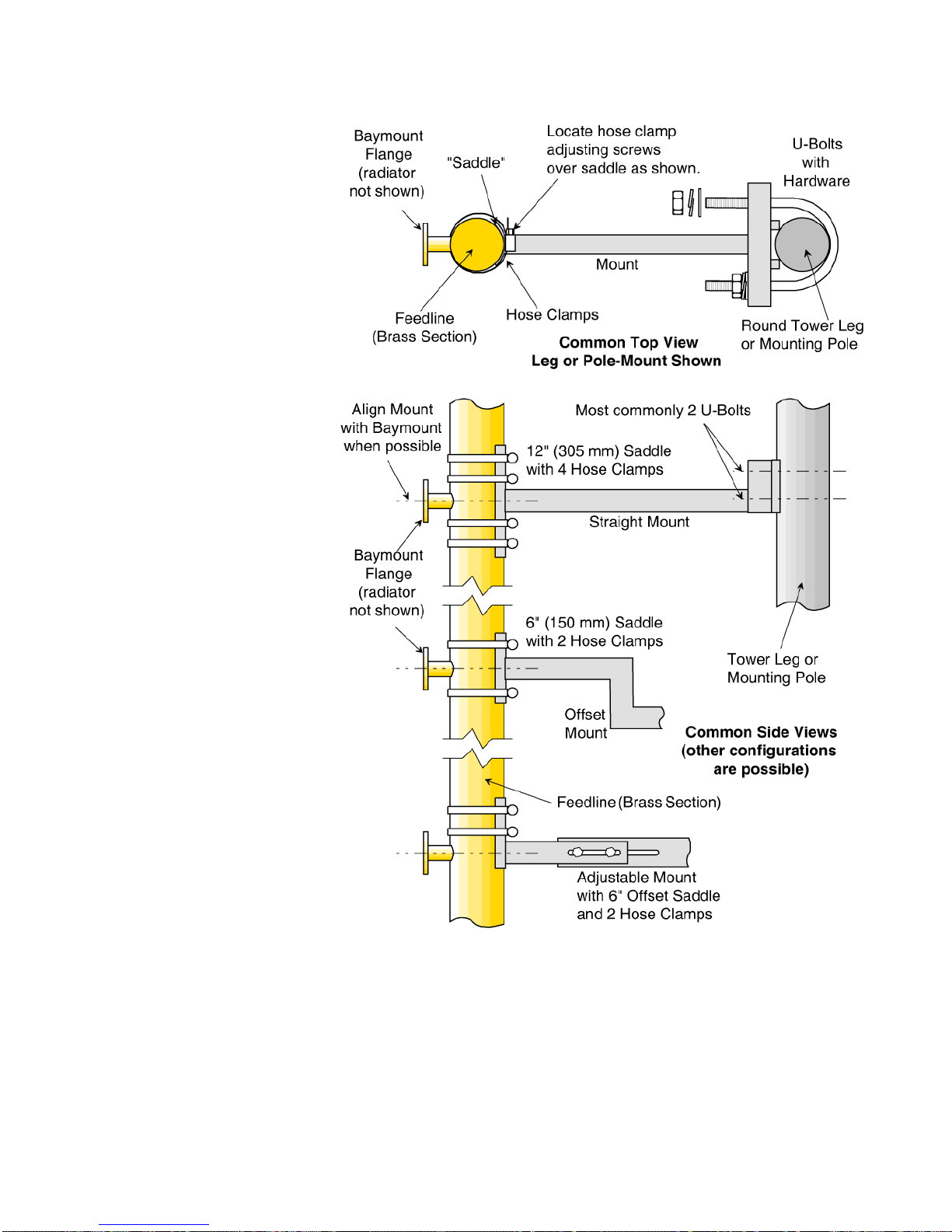
Figure 6 Common Mounting Styles................................................. 10
Installing the Feedline Sections............................................................11
Figure 7 Common Feedline Mount Configurations ........................... 12
Installing the Transformer ...................................................................13
Figure 8 Transformer Installation, top view .................................... 13
Chapter 5 Installing the De-Icer System (if applicable)..................15
Before Beginning De-Icer Installation: .................................................. 15
Installation Procedure.......................................................................... 15
Figure 9 De-Icer Electrical Schematic............................................. 16
Figure 10 Bay Junction Box Installation.......................................... 17
Figure 11 Mounting of Bottommost Bay Junction Box (as needed) ... 17
Figure 12 Shively De-Icer Control Box Layout................................. 18
Figure 13 De-Icer Control Box Electrical Schematic ......................... 19
Table 2 Single Thermostat Readings ............................................. 20
Table 3 Tandem Thermostat Readings .......................................... 20
Table 4 De-Icer Specifications ....................................................... 21
Chapter 6 Startup.............................................................................23
Before Beginning Startup:....................................................................23
Pressurization ..................................................................................... 24
Leak Testing .................................................................................24
Figure 14 Pressurized Gas Schematic............................................. 25
Purging the System....................................................................... 25
Table 5 Volume of Coax per 1000 Feet of Length............................ 26
Leaving the System Pressurized......................................................26

ii
Table of Contents
Initial Characterization (recommended) ................................................ 27
Transmission Line VSWR Reading...................................................27
Transmission Line TDR Reading......................................................27
System VSWR Reading .................................................................. 27
Checking Radiator Function............................................................ 27
Adjusting the Transformer (Impedance Trimming).................................28
Figure 15 Impedance-Matching Transformer .................................. 28
Table 6 Factory Control Rod Settings ............................................. 28
Checkout............................................................................................29
Chapter 7 Operation.........................................................................31
Precautions......................................................................................... 31
The Antenna....................................................................................... 31
The De-Icer System ............................................................................31
Chapter 8 Troubleshooting...............................................................33
Precautions......................................................................................... 33
Internal Arcing....................................................................................33
Table 7 Troubleshooting Internal Arcing ........................................ 33
Broad Spectrum RF Noise ....................................................................33
High VSWR at Startup or during Operation............................................34
Table 8 Troubleshooting High VSWR ............................................. 34
Erratic VSWR During Transformer Adjustment (Impedance Trimming) .... 35
Change in Coverage............................................................................ 35
Pressure Loss or Excessive Gas Usage .................................................. 35
Table 9 Troubleshooting Pressure Loss or Excessive Gas Usage....... 36
Chapter 9 Maintenance ....................................................................37
Precautions......................................................................................... 37
Maintenance Log.................................................................................37
Physical Inspection.............................................................................. 37
De-Icer Check.....................................................................................38
Paint.................................................................................................. 38
Radiator Removal for Repair ................................................................38
Troubleshooting..................................................................................39
Return Policy ......................................................................................39
Sample Maintenance Log.....................................................................40

1
Preparing for Installation
1 Preparing for Installation
Receiving As soon as you receive your antenna,
BEFORE
signing for the shipment:
a. Check to be sure all the material has arrived.
NOTE
The box number and the total number of boxes are marked on each box;
for example, “Box 2 of 5” means “box number 2 of a total of five boxes.”
b. Check for evident damage to any of the boxes.
c. If any boxes are missing, or if any are obviously damaged, describe the
problem in a WRITTEN note on the shipping papers BEFORE signing them.
Then call Shively right away, and we’ll do everything we can to correct the
situation.
Important!
Never store the antenna system outdoors, boxed or otherwise. Take
pains to keep the antenna components dry. You will need to purge mois-
ture from the interior of the antenna components before applying trans-
mitter power, and purging will be much more time-consuming if the
components get wet.
Unpacking a. Find Box 1; it is marked “Open This Box First.” It contains the transformer
and two copies of the installation drawing. The parts list on one sheet of the
installation drawing shows what box each item is in.
b. Then open the boxes and examine for shipping damages. File any necessary
claims with the carrier immediately.
c. If all the boxes are present and in good condition but material seems to be
missing, please contact Shively Labs immediately, using the telephone or Fax
number on the inside cover of this manual. For the best service, have our
shop order number (S/O) handy; it's in the block at the bottom right corner
of the installation drawing.
d. Along with your antenna you will get a spare parts kit. Place this in a safe
place until it is needed.
CAUTION
All contact surfaces and openings to the interior of the components are
protected from contamination and from physical damage by caps and
plastic bags. Do not remove this protection until ready to connect the
components.
Check the System Remember!
It is YOUR responsibility to ensure that your installation meets all appli-
cable codes and the centerline-of-radiation requirements of your FCC
construction permit.
Shively's factory designer has planned the installation of the antenna based
upon information provided by you. If this information contained errors, the
parts and mounting hardware will have been designed incorrectly and will
cause expensive delays in installation.
Therefore, we recommend that you
recheck the installation parameters during this planning stage.

Preparing for Installation
2
Check all the parts to be sure that they will fit the tower and each other. Study
the installation drawings carefully to confirm that the information used in
designing the antenna and mounts was, in fact, accurate.
Have a reliable tower person, familiar with antennas and coaxial line, inspect
the tower and review the installation drawings before the full rigging crew
arrives.
If design problems are found, contact Shively Labs immediately. Pay particu-
lar attention to:
• Frequency of the antenna.
• Fit of the mounts to the tower members.
• Freedom from interference by gussets, leg flanges, guys and their
attachment points, tower face members, obstruction lights, and
other components.
• Compatibility of transmission line and antenna input terminals.
• Location of the transmission line run relative to the antenna input
terminal.
• Use of non-metallic guy sections on the tower in the region to be
occupied by the FM antenna. Ensure that there are no metal guys
within ten feet (three meters) of any radiator.
• Availability of proper electrical service for deicers, if applicable.
• The adequacy of the tower structure and guys to carry the wind-
load placed upon them by the antenna, particularly if radomes are
used.
You gave Shively this information at the time of purchase, but a last check at
this time can catch an error, which will be easier to correct before installation
begins.

3
Installing the Radiators
2 Installing the Radiators
Before Beginning
Radiator Installation: Important!
Feedstrap orientation is critical to performance. In general, the feed-
straps in a full-wave-spaced antenna will all be oriented the same, while
those in a half-wave-spaced antenna will alternate.
Install each radiator
in accordance with its stenciled bay numbers and its "up-arrow" sticker.
Also, be very careful not to disturb or damage the feed strap when han-
dling the radiator.
CAUTION
Radiators and feedline sections are stenciled with their respective bay
numbers (bay #1 is the topmost bay). Assemble components in accor-
dance with their match-markings. If you don’t, the antenna may not per-
form as expected.
CAUTION
All contact surfaces and openings to the interior of the components are
protected from contamination and from physical damage by caps and
plastic bags. Do not remove this protection until ready to connect the
components.
CAUTION
Do not use silicone grease on an O-ring, as this will soften the silicone
O-ring.
Use only a light lubricating coat of petroleum jelly (provided); too much
may hamper electrical contact and contaminate the interior of the sys-
tem.
Be sure the O-ring is properly seated in its groove and not pinched
between the flange contact surfaces.
Installation Procedure It will be easiest to mount the radiators onto the feedline sections before the
feedlines are mounted on the tower.
a. Pair up the feedline sections and the radiator assemblies, using the bay
number stenciled on each piece.
b. Lay a feedline section horizontally, supported off the ground, with its
baymount flange pointing upwards.
CAUTION
To prevent damaging the copper feedline, use hose clamps rather than
U-bolts, and don’t overtighten.
c. Secure the feedline section at the brass end, using hose clamps, to prevent
its turning with the weight of the radiator.

Installing the Radiators
4
Figure 1. Baymount Detail
d. Remove the plastic bag and protective cover (see Figure 1) from the
baymount flange on the feedline.
e. Make sure the inner conductor connector is in place and secure in the inner
conductor of the baymount flange.
NOTE
The hardware is shipped in place on the baymount flange.
f. Remove the O-ring and coat it lightly with petroleum jelly (supplied with the
antenna), then reinstall it in the O-ring groove in the flange.
g. Make sure an inner conductor connector is in place in the inner conductor of
the line section.
Figure 2. Radiator Installation,
exploded view
h. Remove the radiator assembly from its protective plastic bag.

5
Installing the Radiators
CAUTION
Be sure the radiator’s inner conductor fits cleanly over the baymount’s
inner conductor connector. If any of the fingers of the connector are
forced outside the radiator’s inner conductor (we call this a "split bul-
let"), this may cause arcing and damage to the antenna.
i. Carefully place the radiator over the flange studs (see Figure 2), and slipping
it over the inner conductor connector.
j. First snug the flange bolts in the sequence shown in Figure 3 on page 5, then
tighten them to the torque specification shown in Table 1 on page 5.
Figure 3. Flange Bolt Tightening
Sequences
k. Clamp the mounting saddle to the feedline, using a hose clamp.
NOTE
The mounting saddle is not required if radomes are to be installed.
l. Repeat the above steps for the remaining radiators.
Table 1. Torque Specifications, Flange Bolts
Transmission Line
Size Bolt Size Torque
7/8" 1/4-20 7 ft-lb 9 N-m
1-5/8" 5/16-18 12 ft-lb 16 N-m
2-1/8" 3/8-16 21 ft-lb 28 N-m
3-1/8" 3/8-16 21 ft-lb 28 N-m
4-1/16" 3/8-16 21 ft-lb 28 N-m
6-1/8" 3/8-16 21 ft-lb 28 N-m


7
Installing the Radomes (if applicable)
3 Installing the Radomes (if applicable)
Before Beginning
Radome Installation: CAUTION
Radome halves are match-marked in pairs (A-A, B-B, etc.). In order to
align the flange bolt holes, be sure to pair them according to their
match-markings.
NOTE
Radome match-markings bear no relation to radiator and feedline mark-
ings. Install any radome on any bay.
Installation of
Radomes
Figure 4. Radome Installation

Installing the Radomes (if applicable)
8
If your system includes radomes, you can most easily install them at this time.
After installing the radiators, install each radome as follows (see Figure 4 on
page 7).
a. Select a pair of radome halves match-marked with the same letter
designation (A and A, B and B, etc.).
b. Identify the top radome half (wide, overlapping mating flange) and the
bottom radome half (narrow mating flange and drain holes).
c. Separate the top radome mount into its two parts by removing the two bolts.
Keep the hardware for reinstallation.
d. Each radome half has a double notch under the mount; the larger outer
notch fits over the feedline and the smaller inner notch fits against the
baymount.
e. The baymount is lined with black foam (see figure 1) to ensure the radome
will fit snugly. Check to be sure the foam is in place; otherwise, it will be
very difficult to seal the radome later. Reinstall the foam if it has come loose.
f. Carefully place the top radome half in place, slipping it under the radiator and
up against the baymount.
g. Slip the removed part of the radome mount into place. Bolt it to the radome
half and then lightly clamp it to the feedline with a hose clamp.
h. Carefully place the bottom radome half inplace, slipping it under the radiator
and up against the baymount, with its flange inside the larger flange of the
upper radome half. Lightly clamp it to the feedline with a hose clamp.
i. Fasten the two radome halves together loosely with the
1/4-20 hardware (a bolt, a nut, 2 flat washers and a lockwasher for each
hole), starting near the feedline and working around both sides to the outer
edge. It may be necessary to squeeze the radome flanges together to start
the nuts.
j. Tighten all hardware securely.
Important
Be very careful to seal the joint completely. If water enters the radome,
the antenna will not perform as expected, and may cause damage to
your entire system.
k. Seal the joint where the radome encircles the baymount with the silicone
sealant supplied with the antenna.

9
Installing Feedline and Transformer
4 Installing Feedline and Transformer
Before Beginning
Feedline and
Transformer
Installation:
Figure 5. Feedline Flange Detail
CAUTION
Mating feedline flanges are stamped with the same number. Assemble
components in accordance with their match-markings (see Figure 5) and
the installation drawing. If you don’t, the antenna may not perform as
expected.
CAUTION
The feedline inner conductors include "bullet guides" (see Figure 5) to
help prevent split bullets. Be sure the bullet guides are in place before
assembly.
Important!
To avoid damage to the antenna, always lift, position, and attach each
section individually. Never try to transport connected feedline sections!
This rule is often violated and is frequently the cause of expensive dam-
age to feedline.
CAUTION
If you don't get good electrical contact between the mounts and the
tower, the antenna may not perform as designed, and may produce
stray signals that will interfere with other services on the tower.
CAUTION
All contact surfaces and openings to the interior of the components are
protected by covers and plastic bags. DO NOT expose these openings
and contact surfaces until ready to connect the components.

Installing Feedline and Transformer
10
CAUTION
Do not use silicone grease on an O-ring, as this will soften the silicone
O-ring.
Use only a light lubricating coat of petroleum jelly (provided); too much
may hamper electrical contact and contaminate the interior of the sys-
tem.
Be sure the O-ring is properly seated in its groove and not pinched
between the flange contact surfaces.
Installing the Feedline
Mounts
Figure 6. Common Mounting
Styles

11
Installing Feedline and Transformer
There are four basic feedline mounting styles:
• Leg mount, where the mount attaches directly to a tower leg
• Pole mount, where the mount attaches directly to a customer-sup-
plied mounting pole. The pole may be mounted alongside or atop
the tower.
• Face mount, where the mount includes a crossbar which horizon-
tally spans two tower legs.
• Two-leg-pick-up mount, where a crossbar spans two tower legs and
extends away from the tower.
Simplified top views of the four styles are shown in Figure 6 on page 10.
Feedline mounts vary from installation to installation, to accomodate various
tower and mounting pole requirements. Figure 7 on page 12 shows several
common configurations.
Your feedline mounts may be one of the common designs shown; if they are
not, they will be shown in detail on your installation drawing.
Before you begin installation, study the mounts, the mounting tower leg(s) or
pole, and your installation drawing carefully, establishing which mount(s) will
be used for each component.
a. On the tower, starting at the top, use a steel measuring tape to find the
location of each bay in accordance with the installation drawing. Mark the
mount locations.
b. Mark the specified location of any accessory mounts, such as for the
transformer or special coax input line sections, to make sure they will fit as
planned.
c. Watch carefully for any interferences by tower members or guy wires which
were not accounted for in the design.
d. Where the mounts will be in contact with the tower or pole, scrape the tower
paint away to ensure good electrical contact.
e. Secure the feedline mounts to the tower leg(s) or mounting pole using
U-bolts.
f. When all mounts are in place, sight along them vertically and align them
before finally tightening the hardware.
g. Touch up any exposed metal on the tower or pole.
If any problems appear during this process, please call Shively Labs and dis-
cuss them with the installation designer.
Installing the Feedline
Sections a. Install the feedline sections, transformer, and other components carefully, in
accordance with your installation drawing and the illustrations in this
chapter.
b. Secure the feedline to the mount saddles using the hose clamps provided
(generally, two hose clamps on a 6"-long saddle and 4 hose clamps on a 12"-
long saddle). To align the antenna to the proper azimuth, match the
stenciled line on the feedline with the weld dot on the top edge of the mount
saddle.
NOTE
You may use anti-seize on
U-bolt threads to help
prevent galling.

Installing Feedline and Transformer
12
Figure 7. Common Feedline
Mount Configurations
Mounts may vary from bay to bay, especially on tapered towers or where
tower obstructions exist. See your installation drawing for your mount
configuration and special requirements, if any.
CAUTION
To prevent damage to feedline, be sure the feedline mount saddles are
located against the brass portion of the feedline, and position the hose
clamp screw housings over the saddles, not against the feedline.

13
Installing Feedline and Transformer
c. As each feedline section is lifted into place, remove the plastic bags and
protective covers from the flanges and install an O-ring, lubricating it with a
light coat of petroleum jelly (provided with the antenna).
d. Secure each feedline section to its mount before installing the next section.
Installing the
Transformer
Figure 8. Transformer
Installation, top view
One of the unique features of Shively Labs antenna systems is the adjustable
impedance-matching transformer provided with the antenna. It allows the
installer to compensate for changes in the input impedance caused by the
installation (tower, conduit, ladder, etc.).
NOTE
The transformer may be oriented in whichever direction you wish (see
Figure 8). Make it easy for yourself to reach for adjustment at startup.
Install the transformer between your transmission line and the feedline. The
male end (with the inner conductor connector in place) always goes at the
top. Transformer mounts are generally similar to feedline mounts and should
be installed the same.

Table of contents
Other Shively Labs Antenna manuals

Shively Labs
Shively Labs 6020 Instruction Manual

Shively Labs
Shively Labs 6822 Owner's manual

Shively Labs
Shively Labs 6814 User manual

Shively Labs
Shively Labs 6812B Owner's manual

Shively Labs
Shively Labs 6810 Operating and safety instructions

Shively Labs
Shively Labs 6810 Owner's manual

Shively Labs
Shively Labs 6017 User manual

Shively Labs
Shively Labs 6812DIN Owner's manual

Shively Labs
Shively Labs 6842 Owner's manual

Shively Labs
Shively Labs Versa2une SLV User manual