Spiderbeam 160-18-4WTH Instructions for use
Spiderbeam 160m Vertical Model 160-18-4WTH
1160-18-4WTH Manual, Ver. 1.7 17-JULY-2021
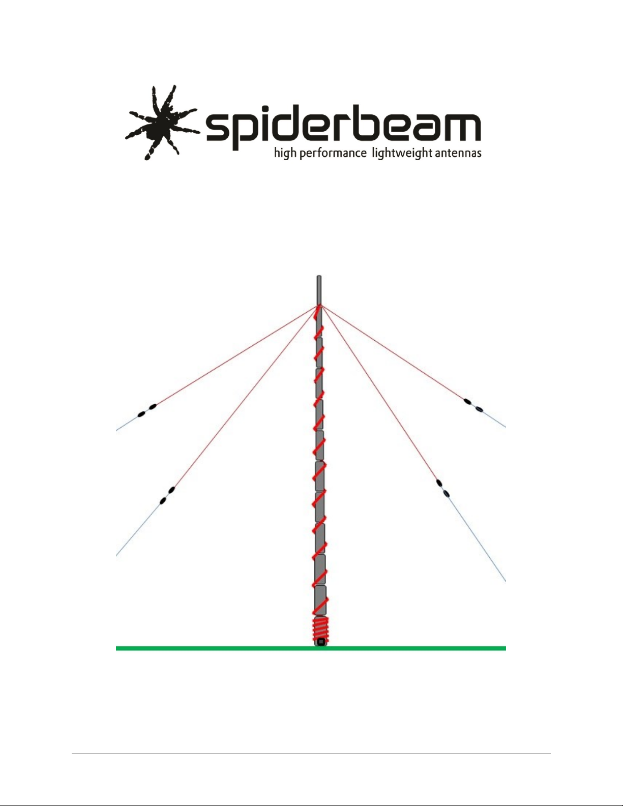
Spiderbeam 160m Vertical
Model 160-18-4WTH
(shown here without radials)

Spiderbeam 160m Vertical Model 160-18-4WTH
2160-18-4WTH Manual, Ver. 1.7 17-JULY-2021
VERTICAL CONSTRUCTION GUIDE
Ver. 1.7

Spiderbeam 160m Vertical Model 160-18-4WTH
3160-18-4WTH Manual, Ver. 1.7 17-JULY-2021
We strongly suggest reading this entire manual BEFORE beginning to work.
CHAPTER CONTENTS PAGE
1.0 Description and Theory 5
1.1 Antenna Description 5
1.2 Required Space 5
1.3 Material Description 6
2.0 Construction 7
2.1 Pole Preparation 7
2.1.1 Tips for Clamp Set Assembly 7
2.2 Wooden Base Stake Preparation and Installation 8
2.3 Attaching the Pole to the Base Stake 8
2.4 Raising the Pole for the First Time 9
2.4.1 Raising and Clamping the Pole Segments 9
2.4.2 Using the Optional Guy Belt Set 10
2.4.3 Using 6mm Rope Stubs instead of Guy Belts 10
2.5 Mounting the Radial Connection Box 11
2.6 Measuring and Cutting Ropes and Wires 12
2.6.1 Table of Measurements 12
2.6.2 Cutting Wire and Ropes 13
2.7 Preparing the Radials 13
2.7.1 Preparing Radial Wires 13
2.8 Preparing the Top-Hat 14
2.8.1 Preparing Top-Hat Wires 15
2.8.2 Connecting the PVDF Monofil Line to the 2nd Top-Hat Insulator 16
2.8.3 High Power Option (>1kW) 17

Spiderbeam 160m Vertical Model 160-18-4WTH
4160-18-4WTH Manual, Ver. 1.7 17-JULY-2021
CHAPTER CONTENTS PAGE
3.0 Installation 18
3.1 Installing the Radiator and Top-Hats 18
3.1.1 Mounting the 4 Top-Hat wires and Vertical Radiator Wire to the Pole 18
3.1.2 Connecting the Vertical Radiator Wire to the Top-Hat Wires 19
3.1.3 Running the Vertical Radiator Wire down the Pole 19
3.1.4 Raising the Pole to its full Height 20
3.1.4.1 Guy Belt Method 23
3.1.4.2 Short Rope Stubs Method 23
3.2 Special Instructions for Erecting the Pole in Windy Conditions 23
3.3 Fastening the Top-Hats to their Ground Stakes 24
3.4 Adjusting Guy ropes and Top-Hat Lines 24
3.5 Installing the Radial Network 25
3.5.1 Installing Ground-Mounted Radials 25
4.0 Tuning the Antenna 26
4.1 Tuning Theory and Methodology 26
4.1.1 It’s time to Tune 27
5.0 Appendix 28
5.1 Appendix A: Materials and Tools List 28
5.1.1 Material included in the kit 28
5.1.2 Other required material (supplied by user) 29
5.1.3 Optional Spiderbeam Material 29
5.1.4 Recommended Tools (Supplied by User) 29
5.2 Appendix B: Preparing Kevlar Rope 29
5.3 Appendix C: Knots 31
Contact: Adress / Email to the Spiderbeam Tech Support 32
Spiderbeam 160m Vertical Model 160-18-4WTH
5160-18-4WTH Manual, Ver. 1.7 17-JULY-2021
1.0 Description and Theory
1.1 Antenna Description
The Spiderbeam Model 160-18-4WTH is a base-fed, [electrical] quarter wavelength vertical
antenna built on a Spiderbeam 18 meter-high telescoping fiberglass pole. It uses 4 top-hat
loading wires to reduce the antenna’s physical height by electrically lengthening the antenna.
This antenna is very easy to build, but does require tuning after it has been erected. It is not
plug and play. Tuning is accomplished by adjusting wire lengths.
Despite being less than 1/8 wavelength in overall height, the Spiderbeam 160-18-4WTH delivers
performance that is very close to that of a full-size vertical antenna on 160m –provided you
have adequate space for proper installation of the top-hat wires and radial network.
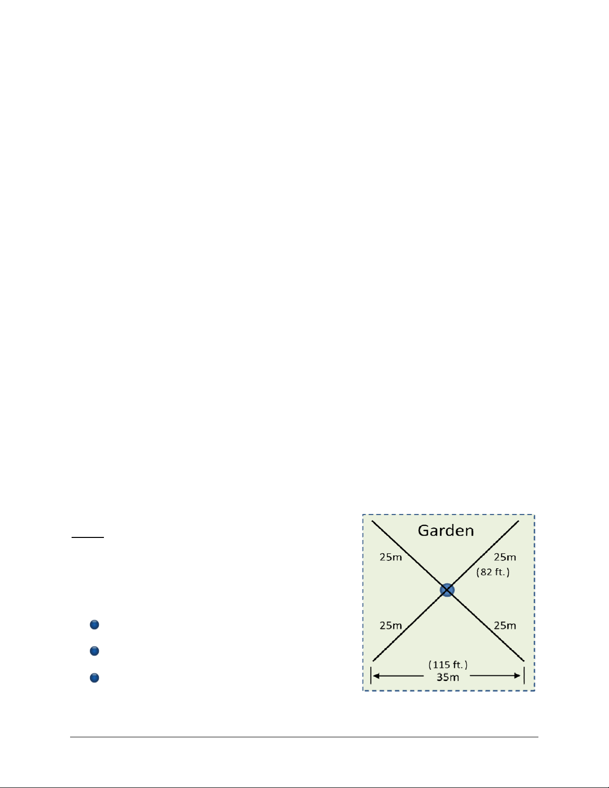
1.2 Required Space
The space required for this antenna is 35m (115’) by 35m, or 1225 sq. meters (~13,000 sq. ft.).
This area should be square, not rectangular. Minor deviations from this will not cause too much
loss in performance. If you have more space, take advantage of it by placing the ground stakes
supporting the top-hat wires farther away from the pole.
The perfect installation would have many wires used for the top hat, and they would all be
mounted in a horizontal plane at the top of the antenna. In real life installations, this is not
possible. A more practical installation will be one with 4 wires sloping to stakes in the ground at
some distant point away from the antenna (typically 25m).
The antenna itself consists of 3 electrical components: the vertical segment of the radiator; the
top-hat segment of the radiator; and a good set of ground-mounted radials. The physical length
of the vertical segment of the radiator is limited by the.
usablelength of the fiberglass pole, which is about 2.
meters less than its physical length. The top-hat wires.
must. always be the same length and equally spaced.
around the pole. Their physical length is determined by.
three factors:
The number of wires used in the top-hat.
The angle of the top-hat wire to the mast.
The ground characteristics at the location.
Other manuals for 160-18-4WTH
1
Table of contents
Other Spiderbeam Antenna manuals

Popular Antenna manuals by other brands

DAVIS
DAVIS Windex AV 3160 installation instructions

Belden
Belden Hirschmann BAT-ANT-N-14G-IP23 Mounting instruction

Vtronix
Vtronix YHK Fitting instructions

KVH Industries
KVH Industries TracVision 6 Technical manual

Leica Geosystems
Leica Geosystems GS10 user manual

Sirio Antenne
Sirio Antenne Gain-Master manual


Feig Electronic
Feig Electronic ID ISC.ANTH200/200 Series manual

TERK Technologies
TERK Technologies TV44 owner's manual

TERK Technologies
TERK Technologies SIR3 owner's manual

Directive Systems & Engineering
Directive Systems & Engineering DSE2324LYRMK quick start guide

HP
HP J8999A instructions

MobilSat
MobilSat MSP-S Mounting instructions