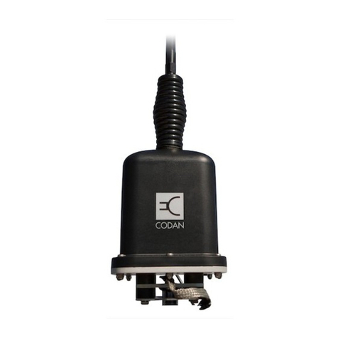
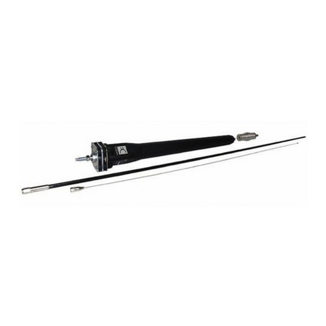
Codan 3048 System manual

RADIO COMMUNICATIONS
Installation Handbook
3048 Tuned Dipole Antenna
Still waiting for the model from Lencom

No part of this manual may be reproduced, transcribed, translated
into any language or transmitted in any form whatsoever without
the prior written consent of Codan Limited.
© Copyright 2013 Codan Limited.
Codan part number 15-04185-EN Issue 1, October 2013.
CODAN™, Envoy™, Easitalk™, and CALM™ are trademarks of
Codan Limited. Other brand, product, and company names
mentioned in this document are trademarks or registered
trademarks of their respective holders.
The English version takes precedence over any translated versions.

TABLE OF CONTENTS
3048 TUNED DIPOLE ANTENNA INSTALLATION HANDBOOK i
Table of contents
Section 1 Introduction
Section 2 Overview
General . . . . . . . . . . . . . . . . . . . . . . . . . . . . 4
Connectors . . . . . . . . . . . . . . . . . . . . . . . . . . 5
Antenna control connector . . . . . . . . . . . . . . . . 5
RF connector . . . . . . . . . . . . . . . . . . . . . . . 6
RF output terminal . . . . . . . . . . . . . . . . . . . . 6
Earth stud . . . . . . . . . . . . . . . . . . . . . . . . . 6
Section 3 Installing the antenna
General . . . . . . . . . . . . . . . . . . . . . . . . . . . . 8
Contents of the antenna pack . . . . . . . . . . . . . . . 8
Required tools . . . . . . . . . . . . . . . . . . . . . . . 11
Footprint of the antenna . . . . . . . . . . . . . . . . . . 11
Typical layout . . . . . . . . . . . . . . . . . . . . . . . 13
Locating the antenna . . . . . . . . . . . . . . . . . . . 14
Earthing the antenna . . . . . . . . . . . . . . . . . . . 14
Cabling . . . . . . . . . . . . . . . . . . . . . . . . . . 16
Installing the antenna . . . . . . . . . . . . . . . . . . . . . 17
Disclaimer . . . . . . . . . . . . . . . . . . . . . . . . . 17
Installation flowchart . . . . . . . . . . . . . . . . . . . 17
Installing the mast . . . . . . . . . . . . . . . . . . . . . 19
Installing the interface unit . . . . . . . . . . . . . . . . 24
Installing the head unit and dipoles . . . . . . . . . . . . 25
Raising the mast . . . . . . . . . . . . . . . . . . . . . 28

TABLE OF CONTENTS
ii 3048 TUNED DIPOLE ANTENNA INSTALLATION HANDBOOK
Connecting the cables from the interface unit to the
transceiver . . . . . . . . . . . . . . . . . . . . . . . . 29
Section 4 Specifications
Specifications . . . . . . . . . . . . . . . . . . . . . . . . 32
Interface requirements . . . . . . . . . . . . . . . . . . . . 33
Section 5 Accessories
Appendix A Compliance
Overview . . . . . . . . . . . . . . . . . . . . . . . . . . . 38
EMC and safety notices . . . . . . . . . . . . . . . . . . . 38
Non-ionising radiation safety . . . . . . . . . . . . . . . 38
Appendix B Definitions
Standards and icons . . . . . . . . . . . . . . . . . . . . . 39
Acronyms and abbreviations . . . . . . . . . . . . . . . . . 40
Units . . . . . . . . . . . . . . . . . . . . . . . . . . . . . 41
Unit multipliers . . . . . . . . . . . . . . . . . . . . . . . . 42
About this issue . . . . . . . . . . . . . . . . . . . . . . . 42
Index

LIST OF FIGURES
3048 TUNED DIPOLE ANTENNA INSTALLATION HANDBOOK iii
List of figures
Figure 1: Front view of the antenna control connector . . . . . . . . 5
Figure 2: Footprint of the antenna . . . . . . . . . . . . . . . . . . . . . . . 12
Figure 3: Base plate for the mast . . . . . . . . . . . . . . . . . . . . . . . . 13
Figure 4: Installation flowchart . . . . . . . . . . . . . . . . . . . . . . . . . 18
Figure 5: Preparing and connecting the bottom and top
sections of the mast . . . . . . . . . . . . . . . . . . . . . . . . . . 21
Figure 6: Laying out and connecting the guy ropes to the
anchor points . . . . . . . . . . . . . . . . . . . . . . . . . . . . . . . 22
Figure 7: Connecting the guy ropes to the erection pole . . . . . . 23
Figure 8: Preparing and connecting the top section of the
mast and the hub tube . . . . . . . . . . . . . . . . . . . . . . . . 26
Figure 9: Inner, centre and outer dipole elements . . . . . . . . . . . 27

LIST OF FIGURES
iv 3048 TUNED DIPOLE ANTENNA INSTALLATION HANDBOOK
This page has been left blank intentionally.

LIST OF TABLES
vi 3048 TUNED DIPOLE ANTENNA INSTALLATION HANDBOOK
This page has been left blank intentionally.

3048 TUNED DIPOLE ANTENNA INSTALLATION HANDBOOK 1
1Introduction
Congratulations on choosing a 3048 Tuned Dipole Antenna to meet
your HF communications needs. You can expect many years of
reliable high performance, and if ever assistance is required,
Codan’s world-class after-sales support team is ready to help.
Please read this handbook thoroughly and retain it for future
reference. There is an index at the end of this handbook to assist
you in finding information.
This handbook is for installers of the 3048 Tuned Dipole Antenna.
It assumes that you have experience in installing RF equipment.
This handbook contains the following sections:
Overview—provides an overview of the antenna and connectors
Installing the antenna—provides guidance on how to position,
install, and earth the antenna
Specifications—provides the common operational, environmental,
physical and interface specifications of the antenna
Accessories—lists the accessories available for the antenna
Compliance—provides compliance information and safety notices
for your antenna
Definitions—explains the terms and abbreviations used in this
handbook
There is an index at the end of this handbook.

INTRODUCTION
2 3048 TUNED DIPOLE ANTENNA INSTALLATION HANDBOOK
This page has been left blank intentionally.

OVERVIEW
GENERAL
4 3048 TUNED DIPOLE ANTENNA INSTALLATION HANDBOOK
General
The 3048 Tuned Dipole Antenna provides continuous tuning for
transceivers that use multiple frequencies. It is designed to
withstand extreme environmental and physical conditions.
The antenna tunes its four 4.8 m dipole elements to a VSWR less
than 1.5:1 over the whole range of 2.5 to 30 MHz. The antenna is
supplied with a purpose-designed 6 m mast, guyed in four
directions at the 3 m and 6 m levels, and includes a pole for ease of
erection. This mast is designed for permanent installation on firm
soils and comes with all necessary components. If the mast is to be
located on sand or soft soils, then concrete anchor points and mast
footing is recommended.
The 3048 Tuned Dipole Antenna is compatible with any Codan HF
transceiver that can control a Codan 3042/3046 Antenna Tuner or
3040/9350 Automatic Tuning Whip Antenna.
TBD diagram needed here

OVERVIEW
CONNECTORS
3048 TUNED DIPOLE ANTENNA INSTALLATION HANDBOOK 5
Connectors
Antenna control connector
The antenna control connector passes control signals between the
Codan HF transceiver and the antenna tuner.
Figure 1: Front view of the antenna control connector
A
B
C
D
E
F
Table 1: Pinouts for the antenna control connector
Pin no. Description
A +12 V DC
BEarth
C Tune
D Scan
E Tune status indicator
F Not used

OVERVIEW
CONNECTORS
6 3048 TUNED DIPOLE ANTENNA INSTALLATION HANDBOOK
RF connector
The RF connector (N-type female) passes RF signals between the
antenna tuner and the transceiver.
RF output terminal
The RF output terminal passes RF signals between the antenna and
the antenna tuner.
Earth stud
The earth stud is used to connect the antenna tuner to earth.

INSTALLING THE ANTENNA
GENERAL
8 3048 TUNED DIPOLE ANTENNA INSTALLATION HANDBOOK
General
The antenna tuner and antenna are critical elements in an HF
communication system. Correct installation of the transmitting
antenna provides efficient operation over the frequency range of
the transceiver. A good installation ensures the antenna tuner
provides optimum output power during transmission and clear
reception of weak signals.
When installing the antenna and tuner you must consider:
• the location and mounting of the antenna
• how to provide a good earth plane for the antenna
• the routing of the coaxial and control cable
• access to connectors
On receiving your antenna, check the contents against the packing
list. Make sure that all equipment itemised on the packing list is
present and that there is no damage to the equipment before you
start installing the system.
If anything is missing or damaged, please contact your nearest
Codan office immediately to obtain the correct warranty service
procedures. This ensures prompt assistance, minimal turnaround
time, and avoids any freight issues.
Contents of the antenna pack
Table 2: Contents of the antenna pack
Item Quantity
Cardboard tube, 3 m long
Mast, top section 1
Mast, base section 1
Star picket 4

INSTALLING THE ANTENNA
GENERAL
3048 TUNED DIPOLE ANTENNA INSTALLATION HANDBOOK 9
Erection pole 1
Cardboard tube, 2 m long
Dipole element, inner (largest diameter, slotted at both ends) 4
Dipole element, centre (non-slotted raw end, and slotted end) 4
Dipole element, outer (non-slotted raw end, caps fitted on outer
end)
4
Carton
Base plate 1
Tent peg 4
Guy assembly, top (marked 2) 1
Guy assembly, bottom (marked 1) 1
Plastic bag
D-shackle 8
Turnbuckle (thimble fitted) 8
M12 x 90 bolt 2
M12 flat washer 4
M12 spring washer 1
M12 nut 2
M8 x 65 bolt 1
M8 flat washer 2
Table 2: Contents of the antenna pack (cont.)
Item Quantity

INSTALLING THE ANTENNA
GENERAL
10 3048 TUNED DIPOLE ANTENNA INSTALLATION HANDBOOK
M8 spring washer 1
M8 nut 1
HV link 2
U-bolt 2
Compression clamp 12
Roll, self-amalgamating tape 4
Bag, Alminox conductive paste 1
Cable tie 4
Miscellaneous
Wire rope grip 16
Interface unit, with captive 7 m RF and control cables 1
Hub tube and 3048 Tuned Dipole Antenna head unit, with fitted
8 mm galvanised bolt, nut and washers
1
8 mm hex head nut driver 1
3048 Tuned Dipole Antenna Installation Handbook 1
Earthing kit 01-1011-001 TBD leave out their part number? (optional, required
for ground mounting) ordered separately?
13 × 1235 mm earth rod 1
50 × 0.5 mm copper strip 5 m
11–25 mm compression clamp 1
Table 2: Contents of the antenna pack (cont.)
Item Quantity

INSTALLING THE ANTENNA
GENERAL
3048 TUNED DIPOLE ANTENNA INSTALLATION HANDBOOK 11
Required tools
The following customer-supplied tools are required during
installation:
• 19 mm spanner for the base fixings
• 13 mm spanner for the mast and head unit fixings
• 12 mm spanner for the U-bolts
• flat-blade screwdriver for the compression clamps
• knife to cut cable ties
• spirit level
NOTE: A step ladder may be used to support the head unit
while it is being assembled.
Footprint of the antenna
The mast and antenna require a certain amount of clear ground
during installation, as shown in Figure 2. The base plate for the
mast must be oriented correctly to allow the mast to lay on the
ground during installation, as shown in Figure 3.

INSTALLING THE ANTENNA
GENERAL
12 3048 TUNED DIPOLE ANTENNA INSTALLATION HANDBOOK
Figure 2: Footprint of the antenna
mast
anchor
point
4 m1 m 8 m
10 m
anchor
point
anchor
point
anchor
point
guy ropes
installation footprint installed footprint
Table of contents
Other Codan Antenna manuals
Popular Antenna manuals by other brands

UEC
UEC HALO manual

Sea Tel
Sea Tel ST24 Operation and installation guide

Diamond Antenna
Diamond Antenna HF50CX installation instructions

Electro-Metrics
Electro-Metrics EM-6912A instruction manual

Teleco
Teleco Flat Sat Classic Smart 85 Installation guide and user's manual

Philex
Philex Slx 27884D4 user guide