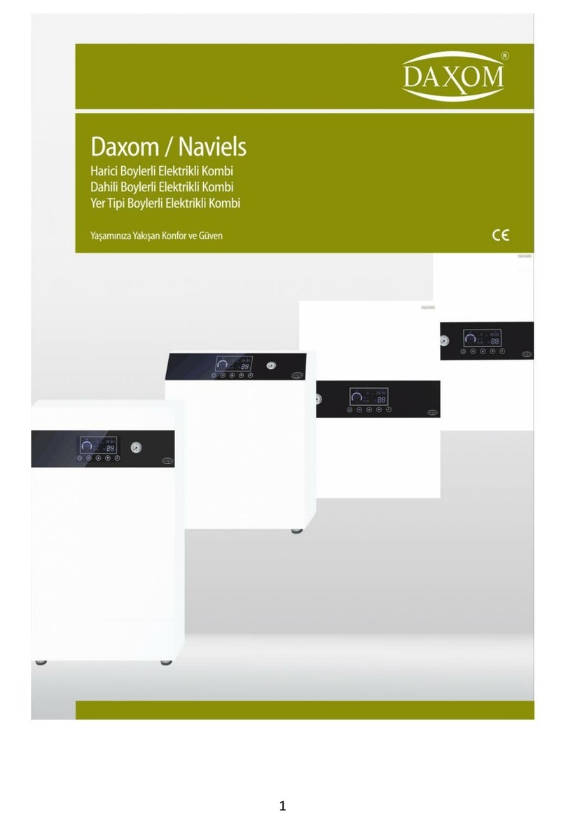
DAXOM UKDAX-10EBT User manual

1

2
TO DAXOM USER
In order to perform device’s function properly and for your safety, follow the
instructions mentioned in the user manual of the device during the mounting
and the usage of the device.
In case of an unauthorized mounting and maintenance, the device will be
void from warranty cover. In addition to that, our company will not be
responsible from failure or an accident that may occur in the device.
Please keep this user manual in good conditions for future reference.
1. SAFETY WARNINGS
Device of the installation must be made by authorized worker according to
instructions which are determined inside this manual.
Startup of the device must be made by Authorized Service. Do not try to
operate device by yourself.
Connections of water and heating installations of the device must be made as
safety.
Device can operate with the voltage determined inside this manual according to
its model. Suitable system voltage must be provided.
When it is supplied electric distribution from any electric resource (like
generator) except city electrical distribution network, must be sure that necessary
conditions are provided for safety operation of the device.
Energy must be provided to device with suitable cable diameter determined
inside this manual. It must definitely have Residual Current Device and
grounding connection.
Installation of the device must not be made to humidity places and places
which can be wet from external factors.
Do not keep inflammable, explosive or easy flammable materials and objects
near or close the device.
This INSTALLATION AND USER MANUAL is supplemental part of the product.
Please keep it for apply when it is necessary. Contact with authorized service
agency for the new copy in case of lost or damage.

3
This device must only be used as suitable for its purpose. Producer reject all
kinds of liabilities that places or not places inside agreement for damage property
or injury intended person or animals which causes because of consumer wrong
using installation, setting and maintenance.
After you unpack the device, be sure that content is in good position and
complete otherwise contact with the sales agency that you have purchased the
device.
Safety valve outlet must be connected to suitable draining system. In case of
damage that occurs because of intervention to safety valve, all responsibilities
are belong to consumer
Remove all packing wastes carefully without giving damage to human and
environmental health.
In case of water leakage happens, water supply must be close and authorized
service agency must be immediately informed.
Heater circuit water pressure must be between 1 and 2 bar and never exceed 3
bar. In case of need, reduce heater circuit water pressure from discharge valve
of installment.
Mg-Anot bar which is inside enameled boiler, provides durability against to
corrosion. MG –Anot bar must be controlled every 3 years and if it is needed it
must be changed.
Domestic water network pressure can be max 6 bar. In case of network
pressure exceeds 6 bar, automatically water discharges from safety valve. In
case of water pressure is over 6 bar, pressure reducer must be installed to inlet
of device or flat tap water.
Hygenic water is provided with with anti-legionary function by increasing boiler
temperature 65C once a day.
If the device will not be used for a long time, performing of following points are
suggested.
Make switch of device OFF
Close water valves both heating and boiler installation.
Discharge heating and boiler for preventing freezing.

4
Device cannot be used by children or disabled people without helper.
In case of having smoked or burning smell originating from device, make the
switch of the device OFF position and contact with authorized service agency.
Do not touch the device with wet hand or when surface of the device is wet.
Do not use substances such as detergent and thinner for the cleaning of the
device. Clean surface of the with damp-dry fabric.
Before using hot water, definitely control the temperature of water.
The lifetime of the device which is determined by Ministry of Custom and Trade
is 10 years
2. SUGGESTIONS FOR ECONOMICALLY USED
Adjust ambient temperature according to your need. Increasing 1 degree of
ambient temperature increases your energy consumption about%6.
Having homogeneous heating at parts according to intended use that is placed
at the heating place, increases saving.
.Having adjustable needed temperature value for every part by using
thermostatic valve for radiators increases the saving but using of room
thermostat and thermostatic valve at the same time can create problem.
For sensing thermostatic valve ambient temperature correctly, make suitable
position of objects such as curtain and goods that influence ambient air flow.
Room thermostat must be far away from windows and heat sources and must be
positioned suitable height for sensing real temperature of the place that is
placed.
Ventilation of heated environment very long time increase the energy lost. Short
time ventilation must be made. If it is needed to make long time ventilation,
closing valve of ambient radiator or reducing the provides energy saving.
At night time or when you are not at home for the short period, if device heating
reduces, can be saving while keeping ambient temperature at definite level is
provided.
Adjustment of device boiler temperature setting according to your need provides
saving.
Use water as consciously. Consciously using water increases saving.

5
3. CONFIGURATION OF DEVICE

6
4. TECHNICAL INFORMATIONS
Your device has got 50 liter integrated enameled boiler. When completely cold , it
takes about 10 min for heating. Because of heating continues while using, device
provides long time using opportunity . It also gives continiues hot water even at low
pressure and low water flow.
Technical Specifications
Model
Power (kW)
Weight Without
Water (Kg)
Boiler
Volume (l)
3~400 V 50 Hz Elektrikli Boiler With Tank
UKDAX-10EBT
10
50
50
UKDAX-12EBT
12
50
UKDAX-16EBT
16
52
UKDAX-18EBT
18
52
UKDAX-20EBT
20
52
UKDAX-24EBT
24
52
1~220 V 50 Hz Electrical Boiler With Tank
UKDAX-6EDM
6
50
50
UKDAX-10EDM
10
50
UKDAX-12EDM
12
50
UKDAX-16EDM
16
52
UKDAX-18EDM
18
52
Technical Specifications
Heating
Tap Water
Min. Operation Pressure
bar
1
-
Max Operation Pressure
bar
3
6
Min. Setting Temperature
oC
35
30
Max. Setting
Temperature
oC
80
65
Connections
inch
3/4
1/2
Dimensions
mm
770*560*390

7
5. INSTALLATION OF DEVICE
Device installation must be done by authorized personnel.

8
5.1. Installation Conditions and Safety Warnings
Obey minimum distance that is anticipated for installation in order to reach the
device for maintenance and repair.
For the right position of the device
Do not place on the cooker or similar cooking devices.
Do not leave combustion products inside the device installed room.
Heating sensitive walls (forexample wooden walls) must be proected with
steady insulation.
Before the installation, wash the system pipes carefully for removing any residual
things that can give damage to operation of the device.
Discharge outlets of safety valves must be connected to close drain with
suitable draining pipe.
When heating system pressure increases over 3 bar, drainage starts from safety
valve.

9
When boiler pressure increases over 8 bar, drainage starts from safety valve.
Boiler max operating pressure is 6 bar. If you suspect that system pressure is
over 6 bar, install pressure reducer to inlet of device or flat entrence
Device installation place must be far away from blockers, obstruction parts and
bulges during repairing and maintenance. There must be sufficient space
arround device for repairing and maintenance.
The electric connection of device must be made with suitable cable and residual
current device and must definitely have ground connection.
Installation wall must be as suitable as carrying weight of device.
5.2. Wall Installation Of Device
Fix the fixing plugs by drilling the appropriate diameter and number of mounting
holes in the place chosen in accordance with the above conditions.
Screw the upper hanger plate of the device tightly. If necessary, screw the hanger
plate in more point. Hold the device by two people opposite to each other, place it
on the hanger plate fixed to the wall. Do not leave the device without making sure
that it is fully fixed. Then screw the lower hanger plate of the device to the wall
tightly and check its durability.
5.2.1. Connection of Heating System and Water Installation
Heating system must be drawn with suitable diameter pipe for providing enough
circulation of heating water. Choosing Radiator pipes smaller than it is needed,
fitting constriction or blockage can inability circulation of heating. Connections that
are made to device must be easy removable when it is needed. There must be
separate cut off valve at device radiator inlet and outlet. Also there must be silt trap
at inlet part between valve and device. Valve and still trap must be used at boiler
cold water inlet.
Make sure that installation wall can carry gross weight of device and device
installed to wall safely.

10
5.2.1.1.Boiler Filling
.
After installment is completed, boiler is needed to fill. This process must be done by
implementing following instructions.
Open device boiler inlet valve
Open any tap connected to device hot water outlet. (preferably nearest tap). Air
inside boiler will be discharged from tap.
Close the tap after air discharged from tap and continuous water flow start.
Water leakage must be controlled studiously.
5.2.1.2. Filling Heating System
. Filling process is done with blue colour filling tap under the device. This process
must be done by implementing following instructions.
Be sure that inlet tap of boiler is open.
Open the filling tap.
When water pressure indicator reaches between 1-1,5 bar, close the filling tap.
Discharge the accumulated air inside radiators by opening air relief cock placed
in side of radiators and close when water starts to flow.
When the accumalted air inside radiators discharge it can be decrease at heating
system water pressure. Make sure that heating system water pressure is
between 1 and 1,5 bar. If decreases, complete by opening filling valve
After boiler is filled, must be studiously controlled if there is water leakage or not
.
After heating system is filled, must be studiously controlled if there is water
leakage or not.
If filling valve is forgot as open and heating systen pressure exceeds 3 bar,
drainage starts from safety valve inside device.

11
5.2.2. Electric Connection
Electrical installation must be done by authorized person according to device
capacity and with suitable diameter cable. Electric of device must have suitable
specification for for cut off device power and residual current device that has amper
value and fuse separately. Fuse must be near to device. Grounding of device must
absolutely be done. If there is not gronding at the place that the device is installed,
grounding must be made for device by authorized person. Operative of grounding
must be controlled in determined periods. Fuse must locate near the device and
device cable must not be strained while connect to fuse. Connection of cables to
fuse must be made by authorized person.
Make sure that cables are connected to correct places.
Loose cable connections can be caused to accidents.
Cable diameter that is calculated according to device capacity and cable length,
residual current device and fuse amper values can be seen at the following table.

12
Model
Power
(KW)
Phase &
Voltage(V)
Current
Drawn (A)
Fuse &
Residual
Current
Device (A)
Cable
Section
(mm)
UKDAX-
10EBT
10
3~400
3*15,2
3*20
5*2,5
UKDAX-
12EBT
12
3~400
3*18,2
3*20
5*2,5
UKDAX-
16EBT
16
3~400
3*24,3
3*25
5*4
UKDAX-
18EBT
18
3~400
3*27,3
3*32
5*4
UKDAX-
20EBT
20
3~400
3*30,4
3*40
5*6
UKDAX-
24EBT
24
3~400
3*36,4
3*50
5*6
UKDAX-
6EBM
6
1~220
27,3
32
3*4
UKDAX-
10EBM
10
1~220
45,6
50
3*6
UKDAX-
12EBM
12
1~220
54,6
63
3*10
UKDAX-
16EBM
16
1~220
72,8
80
3*16
UKDAX-
18EBM
18
1~220
81,9
100
3*16
Cable sections at this table are calculated for maximum 10m. Consult
your authorised service for more than 10m cable length.

13
6.DEVICE OPERATION AND USAGE
6.1. LCD Display
Operating Condition and settings of the device can be follow from LCD panel.
Radiator Operation Indicator
Floor Heating Indicator
Days Of Week
Time programming. Can be made 7 pcs
time programming
Hour
Capacity Indicator
Ready to operation indicator
Hot Water Heating Indicator
Radiator Heating Indicator
Over Temperature Indicator
Over Temperature Difference Value
Pump Operation Indicator
Freezing Prevention Indicator
Temperature Indicator

14
6.2. Control Buttons
Control of the device is done with buttons placed under the LCD Display.
6.3. Operation of Device
Before operating the device, suitability of all connections of mechanics and
electrical must be controlled. Heating system must be completely filled and radiator
vent must be done. Our company is not responsible from damages and accidents
which can be occur because of wrong connection.
Follow following points for operation of device.
Make sure that device water and radiator valves are open
Open residual current device then fuse
First operation of the device must be absolutely done by authorized service.
Our company is not responsible from damages and accidents which can be
occured with intervention to device by unauthorized people.

15
After all symbols on the LCD screen appear a few min, LCD screen will be as in
the following
Hold 2-3 min to button for device ON
Device keeps last settings in its memory before OFF. When it is ON again,
starts to operate with same settings.
When operation off device is set as boiler and radiator heating before OFF
position if boiler temperature is lower than set temperature, device operates for
boiler heating. and symbols are seen with “heating”and “shower”,
symbol blinks

16
If boiler temperature is equal or over the set temperature , device operates for
radiator heating. and symbols are seen with “heating”and “shower”,
expression.
When operation of the device is set as boiler heating before OFF position if
boiler temperature is lower than set temperature, device operates for boiler
heating and symbols are seen with “heating”and “shower”,
expressions symbol blinks. If boiler temperature is equal or more than the
set temperature, device passes to standby position.
When operation of the device is radiator heating before OFF, device operates for
radiator heating. is seen with “heating” word. after pump operates about 1
min, device starts to radiator heating. is seen.
Warning beep is heard after process of pressing knob. For long time pressing
knobs (forexample 2-3 seconds), before hearing warning warning beep, it does not
mean pressing knob.

17
6.4. Operation Parameter Setting
6.4.1. Day anf Hour Setting
Switch OFF the device
Hold button 5-6 seconds. Days start to blink.

18
Days are set by pressing with one second intervals to or buttons.
Press button hour blinks.
By pressing or one second interval hour is set between 0 and 23

19
Press button , minute blinks.
By pressing or button one second interval min set between 0 and
60.
By pressing button or if not pressing any button for a 10 sec , exit
from setting menu by saving settings.

20
6.4.2. RADIATOR TEMPERATURE SETTING
While or symbols are seen at LCD Display, (when device is operating for
radiato system) radiator heating setting can be made between 35 oC and 80 oC by
pressing or buttons. While radiator heating setting is made, “Water Temp”
expression fizzle out, setting temperature value starts to blink. While the device is
operating for boiler heating, device operation mode must be changed as radiator
heating for setting radiator temperature. At the end of the process, device must be
taken to previous operation mode. (Check 6.4.8)
After 2 sec later setting completed, device operation temperature and “Water
Temp” expression are seen at the LCD. Reaching seeting temperature of device
may take time. After tap water heating is completed, radiator heating does not start
immediately, radiator heating starts after pump operates for a while for temperature
balance.
Other manuals for UKDAX-10EBT
2
This manual suits for next models
10
Table of contents
Other DAXOM Electric Heater manuals
Popular Electric Heater manuals by other brands

tresnar
tresnar 7111 instruction manual

REMKO
REMKO EM Series Operating and installation instructions

Sunred
Sunred WMC1800R manual

Harvia
Harvia CS60 Instructions for installation and use

Infratech
Infratech ALL WEATHER QUARTZ TUBE ELECTRIC HEATER Installation use & care instructions

Rointe
Rointe D SERIES instruction manual