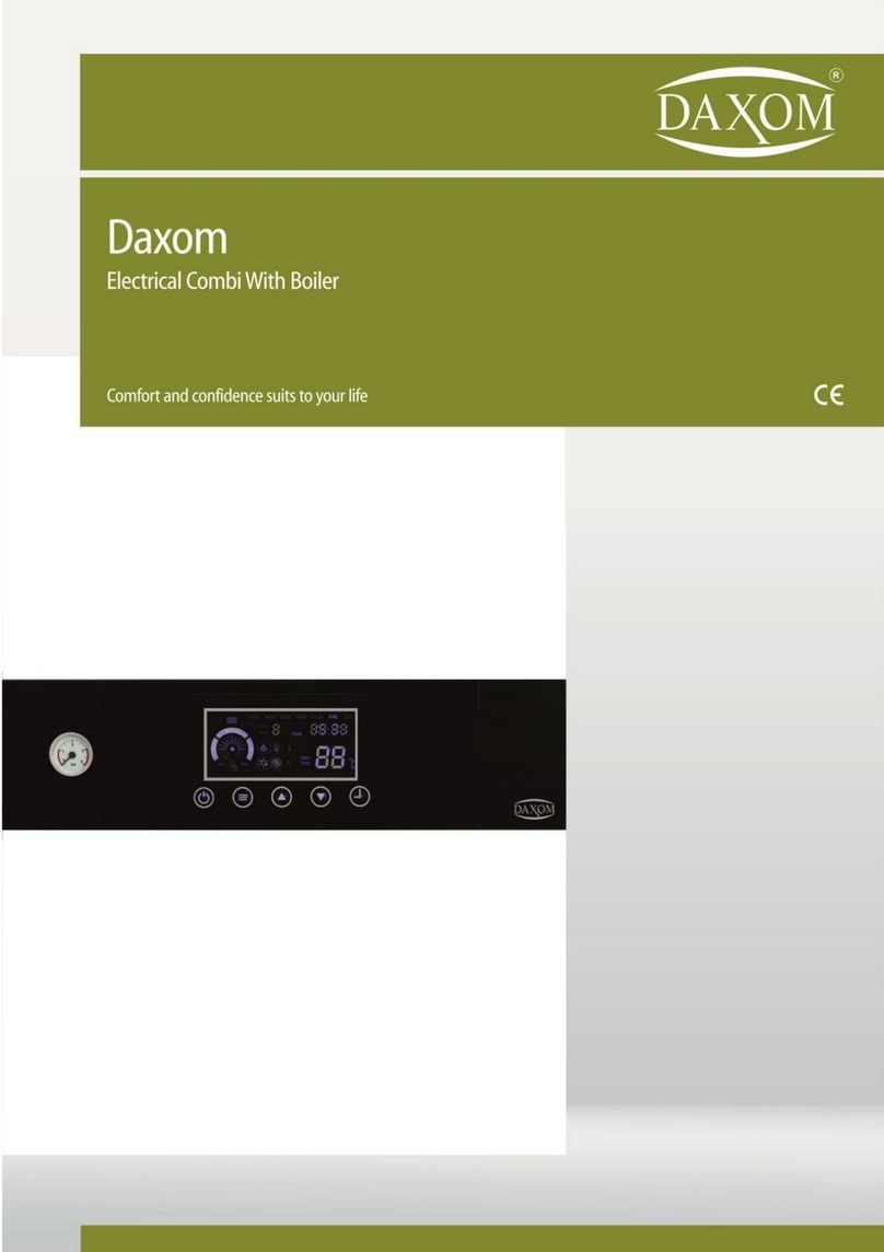
DAXOM UKDAX-10EBT User manual

1

2
Değerli Daxom Kullanıcısı,
In order to perform device’s function properly and for your safety follow the
instructions mentioned in the user manual of the device during the mounting and
the usage of the device. In case of an unauthorized mounting and maintenance, the
device will be void from warranty cover. In addition to that, our company will not be
responsible from failure or an accident that may occur in the device. Please keep
this user manual in good conditions for future reference.
1. SAFETY WARNINGS
Device installation must be made by authorized personnel according to
instructions that are determined inside this manual.
Start-up of device must be made by Authorized Service. Do not try to
operate the device by yourself.
Connection of water and heating installment of the device must be made
as safety
Device can operate with the voltage determined inside this manual
according to its model. Suitable system voltage must be provided.
When it is supplied electric distribution from any electric resource (like
generator) except city electrical distribution network, must be sure that
necessary conditions are provided for safety operation of the device.
Energy must be provided to device with suitable cable section determined
inside this manual. Residual Current Device and grounding must definitely
place.
Installation of the device must not be made to humidity places and places
that can be wet from external factors.
Do not keep inflammable, explosive or easy flammable materials or
objects near or close the device.
This “INSTALLATION AND USER MANNUAL” is supplemental part of the
product. Please keep it for apply when it is necessary. Contact with
authorized service agency for the new copy in case of lost or damage.
This device must only be used as suitable as for its purpose. Producer
reject all kinds of liabilities that places or not places in the agreement for
damage property or injury indented to person and animals which cause
because of consumer wrong using, installation, setting and maintenance.
After you unpack the device, be sure that content is in good position and
complete otherwise contact with the sales agency that you have
purchased the device.
Safety valve outlet must be connected to suitable discharge system. All
responsibilities are belong to user in case of any damage that occurs
because of any intervention to safety valve.
Remove all packing wastes carefully without giving damage to human and
environment health.
In case of water leakage happens, water feed must be close and
authorized service agency must be immediately informed.

3
Hydraulic system operation pressure must be between 1 and 2 bars
therefore it must not exceed 3 bars. In case of need reduce water pressure
of heater circuit from discharge valve of installment.
Mg-Anot bar which is inside enameled boiler, provides durability against to
corrosion. MG –Anot bar must be controlled every 3 years and if it is needed it
must be changed.
Domestic water network pressure can be max 6 bar. In case of network
pressure exceeds 6 bar, automatically water discharges from safety valve. In
case of water pressure is over 6 bar, pressure reducer must be installed to inlet
of device or flat tap water.
Hygenic water is provided with with anti-legionary function by increasing
boiler temperature 65C once a day.
If the device will not have used for a long time, perform following points
are suggested.
Bring switch of the device OFF position.
Close taps both heating and hot water network.
Discharge heating installation and boiler cycle for preventing
freezing.
Device cannot be used by children or disabled people without helper.
In case of having smoked or burning smell originating from device, make switch
of the device”OFF” position and contact with authorized service agency.
Do not touch the device with wet hand or when outside of device is wet.
Do not use substances such as detergent and thinner for the cleaning of the
device. Clean outside of the device with damp –dry fabric after make switch of
device OFF.
Absolutely control temperature of hot water before using.
The lifetime of the device which is determined by Ministry of Custom and trade
is 10 years

4
2. SUGGESTIONS FOR ECONOMICALLY USED
Adjust ambient temperature according to your need. Increasing 1 degree
of ambient temperature increases your energy consumption about %6.
Having homogeneous heating at parts according to intended use that is
placed at the heating place, increases saving.
By using thermostatic valve for radiators, having adjustable required
temperature value for every section increases saving but using room
thermosatd and thermoatatic valve at the same time can cause problem
For sensing thermostatic valves ambient temperature correctly, curtains or
objects that affect air flow must be positioned properly.
For sensing room thermostad ambient temperature correctly that it placed,
it should be positioned far and proper height from window, object or heat
source.
Ventilation of heated environment very long time increase the energy lost.
Short time ventilation must be made. If it is needed to make long time
ventilation, closing valve of ambient radiator or turn the device down
provide energy saving.
At night time or when you are not at home for a short time, if device
temperature is decreased, can be saved while providing keep the
temperature at sufficient level.
Adjustment of device operation temperature setting according to exterior
temperature provides saving.
Use water as consciously. Consciously using water increase saving.

5
3. CONFIGURATION OF THE DEVICE
Wall Type Boiler With Tank
Floor Type Boiler With Tank

6
Wall Type External Boiler With Tank

7
4. TECHNICAL INFORMATIONS
UKDAX-xxEBM ,UKDAX-xxEBT ,UKDAX-xxYxxBT ve UKDAX-xxYxxBM devices
have got integrated enameled boiler. Because of heating continiues while using, it
provides long time using opportunity. It also gives continiues hot water even at low
pressure and low water flow.
Wall Type Boiler With Tank
Technical Informations
Model
Power (kW)
Weight Without
Water
Boiler
(Kg)
Volume(l)
3~400 V 50 Hz Electrical Boiler With Tank
UKDAX-10EBT
10
50
UKDAX-12EBT
12
50
UKDAX-16EBT
16
52
50
UKDAX-18EBT
18
52
UKDAX-20EBT
20
52
UKDAX-24EBT
24
52
1~220 V 50 Hz Electrical Boiler With Tank
UKDAX-6
EBM
6
50
UKDAX-10 EBM
10
50
UKDAX-12 EBM
12
50
50
UKDAX-16 EBM
16
52
UKDAX-18 EBM
18
52
Technical
Informations
Heati
ng
Boiler
Min. Operation Pressure
bar
1
-
Max. Operation Pressure
bar
3
6
Min. Temperature Setting
oC
35
30
Max. Temperature
Setting
oC
80
65
Connections
inch
3/4
1/2
Dimensions
mm
770*560*390

8
Floor Type Boiler With Tank
Technical Informations
Model
Power
(kW)
Boiler
Capacity
(l)
Weight
Without
Water
(kg)
Dimensions
Y*G*D
(mm)
3~400 V 50 Hz Electrical Boiler With Tank
UKDAX-80Y10BT
10
80
81
836*600*590
UKDAX-80Y12BT
12
80
81
836*600*590
UKDAX-80Y16BT
16
80
83
836*600*590
UKDAX-80Y18BT
18
80
83
836*600*590
UKDAX-80Y20BT
20
80
83
836*600*590
UKDAX-80Y24BT
24
80
83
836*600*590
UKDAX-120Y10BT
10
120
103
1152*600*590
UKDAX-120Y12BT
12
120
103
1152*600*590
UKDAX-120Y16BT
16
120
105
1152*600*590
UKDAX-120Y18BT
18
120
105
1152*600*590
UKDAX-120Y20BT
20
120
105
1152*600*590
UKDAX-120Y24BT
24
120
105
1152*600*590
1~220 V 50 Hz Electrical Boiler With Tank
UKDAX-80Y10BM
10
80
81
836*600*590
UKDAX-80Y12BM
12
80
81
836*600*590
UKDAX-80Y16BM
16
80
83
836*600*590
UKDAX-80Y18BM
18
80
83
836*600*590
UKDAX-120Y10BM
10
120
103
1152*600*590
UKDAX-120Y12BM
12
120
103
1152*600*590
UKDAX-120Y16BM
16
120
105
1152*600*590
UKDAX-120Y18BM
18
120
105
1152*600*590
Technical Informations
Radiator
Tap
Water
Min. Operation Pressure
bar
1
-
Max. Operation Pressure
bar
3
8
Min. Temperature Setting
°c
10
35
Max Temperature Setting
°c
80
65
Connections
İnch
3/4
1/2

9
Waşş Type External Boiler With Tank
Technical Informations
Model
Power
Dimensions
Weight
Expansion
(kW)
Y*G*D (mm)
(Kg)
Tankı (l)
3~400 V 50 Hz Electrical Boiler With External Tank
UKDAX-10HBT
10
700*400*220
23,5
7
UKDAX-12HBT
12
700*400*220
23,5
7
UKDAX-16HBT
16
700*400*220
25,0
7
UKDAX-18HBT
18
700*400*220
25,0
7
UKDAX-20HBT
20
700*400*220
25,0
7
UKDAX-24HBT
24
700*400*220
25,0
7
UKDAX-30HBT
30
700*450*320
32,2
12
UKDAX-36HBT
36
700*450*320
35,4
12
UKDAX-40HBT
40
700*450*320
35,4
12
UKDAX-48HBT
48
700*450*320
35,4
12
1~220 V 50 Hz Electrical Boiler With External Tank
UKDAX-6HBM
6
700*400*220
23,5
7
UKDAX-10HBM
10
700*400*220
23,5
7
UKDAX-12HBM
12
700*400*220
23,5
7
UKDAX-16HBM
16
700*400*220
25,0
7
UKDAX-18HBM
18
700*400*220
25,0
7
General Technical Informations
Min. Operation Pressure
bar
1
Max. Operation Pressure
bar
3
Radiator Operation Setting
Temperature
°c
10-80
Boiler Operation Setting
Temperature
°c
35-65
Radiator Connections
İnch
3/4
Boiler Connections
İnch
3/4
Water Filling Connection
İnch
1/2

10
5. INSTALLATION OF DEVICE
Wall Type Boiler With Tank
Device installation must be done by authorised personnel.

11
Floor Type Boiler With Tank
[UKDAX-80YxxBT / UKDAX-80YxxBM]
Simge
a
b
c
d
e
f
g
h
Ölçü(mm)
600
836
84
149
214
84
186
590

12
Floor Type Boiler With Tank
[UKDAX-120YxxBT / UKDAX-120YxxBM]
Simge
a
b
c
d
e
f
g
h
Ölçü(mm)
600
1152
84
149
214
84
186
590

13
Installation Of Floor Type Boiler With Tank
[UKDAX-80YxxBT / UKDAX-80YxxBM]

14
[UKDAX-120YxxBT / UKDAX-120YxxBM]

15

16
Wall Type Boiler With Tank
Kapasite
a
b
c
d
e
f
g
h
i
j
k
l
10-24
KW
700
400
220
58
122
277
342
65
200
123
100
200
30-48
KW
700
450
320
83
147
302
367
75
225
148
100
225
*ölçüler mm cinsindendir.

17
Plumbing Connection Diagram Of External Boiler With Tank:

18
5.1. Installation Conditions and Safety Warnings
Obey minimum distance that is anticipated for installation in order to reach the
device for making maintenance and repair.
For Correct Device Installation;
Installation must not be made on the cooker or similar cooking devices.
Do not leave combustion products inside device installed room.
Heating sensitive walls (for example wooden walls) must be protected with
steady insulation.
Before the installation, all system pipes must be washed carefully for
removing any residual things that can give damage to operation of the
device.
Discharge outlets of safety valves must be connected to close drain with
suitable draining pipe.

19
When heating system increases over 3 bar, water disposal starts from safety
valve.
For Ukdax-xxHBT ve Ukdax-xxHBM models , 50 K NTC boiler sensor must be
installed.
When boiler pressure increases over 8 bar, drainage starts from safety valve. (
For Ukdax-xxEBM ve Ukdax-xxEBT )Boiler max operating pressure is 6 bar. If
you suspect that system pressure is over 6 bar, install pressure reducer to inlet
of device or flat entrence
Device installation place must be far way from blockers, obstruction parts
and bulges during repairing and maintenance. There must be sufficient
space around the device for maintenance and repair.
Electric connection of the device must be made with suitable cable, fuse
and residual current device and grounding absolutely must be made.
Installation wall of the device must be as durable as carrying the weight of
the device.

20
.
5.2. Wall Installation Of Device
Fix the fixing plugs by drilling the appropriate diameter and number of mounting
holes in the place chosen in accordance with the above conditions.
Screw the upper hanger plate of the device tightly. If necessary, screw the hanger
plate in more point. Hold the device by two people opposite to each other, place it
on the hanger plate fixed to the wall. Do not leave the device without making sure
that it is fully fixed. Then screw the lower hanger plate of the device to the wall
tightly and check its durability.
Installation wall of the device must be as durable as carrying the weight
of the device.
Other manuals for UKDAX-10EBT
2
This manual suits for next models
44
Table of contents
Other DAXOM Electric Heater manuals
