Dyna-Glo EG7500DG Manual

1
09/01/2017
Heavy Electric Utility Heater
Model: EG7500DG
“USER’S MANUAL AND
OPERATING INSTRUCTIONS”
MODEL: EG7500DG
Before the rst use of this heater, please read this USER’S MANUAL
very carefully. This USER’S MANUAL has been designed to instruct
you as to the proper manner in which to assemble, maintain, store,
and most importantly, how to operate the heater in a safe and efcient
manner. Please keep this manual for future reference.
CONSUMER : Retain this manual for future reference.
Questions, problems, missing parts? Before returning to your retailer, call our customer
service department at 877-447-4768 8:30 a.m. - 4:30 pm CST, Monday - Friday.
4003667
CONFORMS TO/CUMPLE CON/
CONFORME TO UL STD.2021
CERTIFIED TO/CERTIFICADO A/
CERTIFIÉ TO CSA STD.C22.2NO.46

2
PET OWNERS WARNING: The health of some small pets including birds are extremely sen-
sitive to the fumes produced during the rst-time use of many appliances. These fumes are not
harmful to humans but we recommended that you do not use your heater around birds and small
pets during its initial use until the manufacturing corrosion coatings burn off.
When using electrical appliances, basic precautions should always be followed
to reduce the risk of re, electric shock, and injury to persons, including the
following:
1. Read all instructions before installing or using this heater.
2. This heater is hot when in use. To avoid burns, do not let bare skin touch
hot surfaces. Keep combustible materials, such as furniture, pillows,
bedding, papers, clothes, and curtains at least 3 feet (0.9 m) from the front
of the heater and keep them away from the sides and rear.
3. Extreme caution is necessary when any heater is used by or near children
or invalids and whenever the heater is left operating and unattended.
4. Always turn off the power of heater when not in use.
5. Do not operate any heater with the heater malfunctions, has been
dropped or damaged in any manner. Return heater to authorized service
facility for examination, electrical or mechanical adjustment, or repair.
6. Do not use outdoors.
7. This heater is not intended for use in bathrooms, laundry areas and
similar indoor locations. Never locate heater where it may fall into a
bathtub or other water container.
8. To disconnect heater, turn controls to off.
9. Do not insert or allow foreign objects to enter any ventilation or exhaust
opening as this may cause an electric shock or re, or damage the heater.
10. To prevent a possible re, do not block air intakes or exhaust in any
manner. Do not use on soft surfaces, like a bed, where openings may
become blocked.
11. A heater has hot and arcing or sparking parts inside. Do not use it in areas
where gasoline, paint, or ammable liquids are used or stored.
12. Use this heater only as described in this manual. Any other use not
recommended by the manufacturer may cause re, electric shock, or
injury to persons.
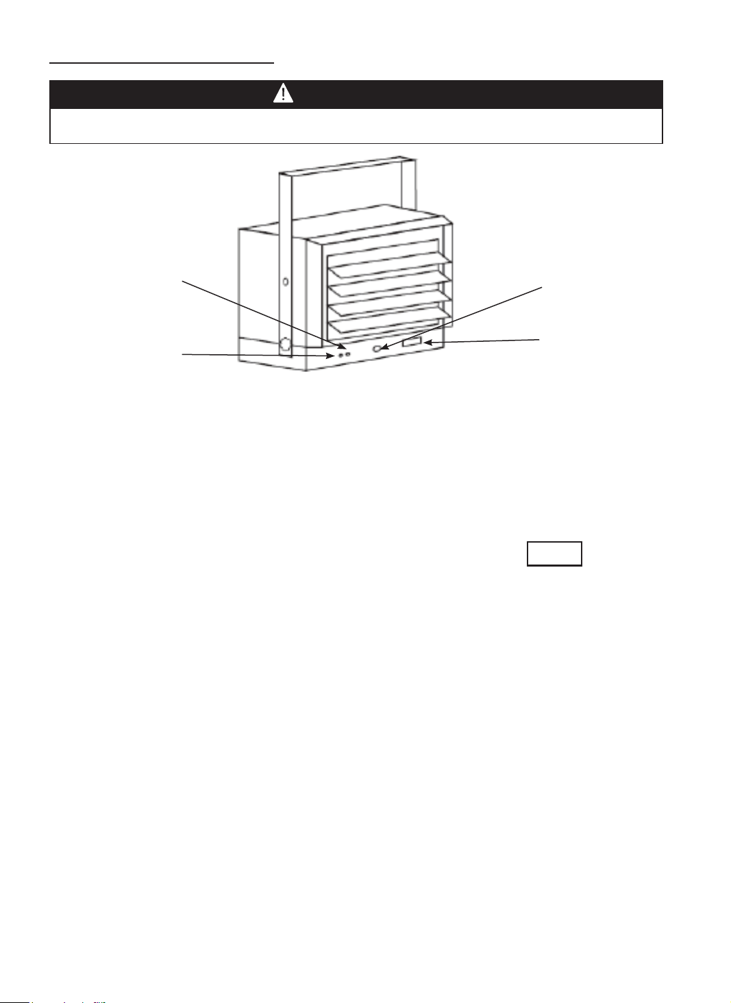
13. This heater may include an audible (a visual) alarm to warn that parts
of the heater are getting excessively hot. If the alarm ashes, immediately
turn the heater off and inspect for any objects on or adjacent to the heater
that may cause high temperatures.
DO NOT OPERATE THE HEATER WITH THE ALARM FLASHING.
IMPORTANT INSTRUCTIONS
SAVE THESE INSTRUCTIONS

3
ITEM PAGE #
PRECAUTIONS - SAFETY GUIDE ................................................. 1
1. DESCRIPTION .......................................................................... 3
2. SPECIFICATIONS ..................................................................... 3
3. GENERAL SAFETY INFORMATION ........................................ 3
4. LOCATING HEATER ................................................................. 5
5. INSTALLATION ......................................................................... 5
6. OPERATING INSTRUCTIONS ................................................. 10
7. MAINTENANCE ........................................................................ 11
DESCRIPTION
Electric utility heaters are designed to meet a variety of heating requirements by switching
a few wires located in the base of the unit. Heat output is 25 589 BTU per hour. Features
horizontal and vertical ow horizontal air ow. Built-in thermostat with overheating safety
thermal cutout.
SPECIFICATIONS
GENERAL SAFETY INFORMATION
CONTENTS OF USER’S MANUAL
This heater requires hardwire installation (no plug). The installation of this
product must be carried out by a certied electrician and in accordance
with all local and national electrical codes.
NOTE: Compatible with a 240V Line Voltage Double Pole Wall Thermostat.
Must be installed by a Certied Electrician.
Read and understand all installation & operation instructions prior to
operating this unit. Observe all safety instructions.
WARNING
WARNING
1. Use only copper wires rated for at least 75ºC.
2. Heater air ow must be directed parallel to or away from adjacent wall.
3. Observe all wall, oor and ceiling clearance requirements.
4. All wiring must be done according to national and local electrical codes. The
heater must be grounded as a precaution against possible electrical shock.
Heater circuit must be protected with proper fuses.
5. The mounting structure and the anchoring hardware must be capable of
supporting the weight of the heater and the mounting bracket (if used).
BTUs: 21,331 / 25,589
Power: 6,250 / 7500W
Volts: 240V / 60HZ

4
6. All electrical power must be disconnected at the main service box, which
must be locked before connecting, inspecting, cleaning or servicing the
heater. This is an important precaution to prevent serious electric shock.
7. This is heater is not suitable for use in hazardous locations containing
explosive liquids or vapours. This heater has hot or arcing or sparking pads
inside. Do not use it in areas where gasoline, paint or ammable liquids are
used or stored.
8. This heater is not suitable for use in corrosive atmospheres such as marine
greenhouses or chemical storage areas.
9. This heater must be mounted at least 8 feet off the oor. For specic
clearances, please see next page.
Install heater away from trafc areas, maintaining clearances stated in gure
2 (below). The air ow direction should not be restricted (ie. by columns or
machinery). The air ow should wipe exposed walls rather than blowing directly
on them. When more than one heater is used in an area, heaters should be
installed so that the air discharge of each heater supports the air ow of the
others, to provide best warm air circulation as shown in gure 3.
GENERAL SAFETY INFORMATION
LOCATING HEATER
Improper installation or failure to follow the procedures outlined in this
instruction manual can result in serious electrical shock.
WARNING
Figure 2

5
Wood Ceiling Wood Ceiling
MOUNTING THE BRACKET
Refer to Figures 4a and 4b.
1. Locate a wood stud in the wood ceiling joist. If you cannot locate a wood
stud, you have to install a wood piece on the ceiling as this heater must be
securely fastened.
2. Remove the mounting bracket from the heating unit by loosening bracket
screws with a wrench and slipping the handle off over the screw heads.
3. Place a washer on screws before inserting through the holes in the mounting
bracket and screw them securely into a ceiling joist.
NOTE: If you want to swivel the heater either to the right or left adding a washer
to both sides of the bracket is recommended. A longer lag bolt may be required
to properly secure the unit. See Figure 4a.
LOCATING HEATER
INSTALLATION
Figure 3
HANGING THE HEATER
1. Attach the heating unit to the mounting bracket.
2. Lift the heater up and into the mounting bracket.
3. Align the bracket screws with the keyhole slots in the mounting bracket.
4. If the heater is to be tilted it must be positioned in the keyhole slots - see
gure 5.
5. Tighten the bracket screws with a wrench so the unit is securely suspended
at horizontal or vertical level.

6
MULTIPLE VERTICAL ANGLES
Figure 5
ADJUSTING AIR FLOW DIRECTION
1. To turn the unit when it has been installed with a single lag bolt (as shown in
gure 4a), simply turn the entire heater as needed. The unit cannot be turned
horizontally if it has been installed with 2 lag bolts.
2. To tilt the unit vertically, loosen the bracket screws (see gure 5).
NOTE: For the heater to be tilted vertically, it must be mounted in bottom
keyhole slots of mounting brackets to maintain adequate clearance and prevent
possible overheating.
3. Adjust louvers to the desired position.
NOTE: The louvers are designed so they cannot be completely closed. Do not
attempt to defeat this feature; damage to the unit can result.
WARNING
To prevent possible electric shock, disconnect power to the heater at the
main service box before attempting to adjust the heat output of this unit.

7
CONNECTING THE POWER
If you will use an external temperature control (external thermostat) to
control the heater to be operated or not, please follow below attention
points:
1. Make sure that the heater's temperature control knob (thermostat knob) is
turned fully clockwise.
2. Connect the wire according to below wiring diagram.

8
Warning: This appliance must be grounded!
Warning: The appliance must connect to a current protection circuit or
device at 50Amp or less before being connected to power supply!
High temperatures – risk of re. Keep ammable materials, such as fur-
niture, pillows, bedding, papers, clothes and curtains at least 3 ft. (0.9 m)
from the front and top of the heater and keep them away from the sides
and rear. To reduce the risk of re, do not use it in areas where gasoline,
paint or ammable liquids are used or stored.
WARNING
WARNING
CAUTION
CONNECTING THE POWER
3. The external temperature control (external thermostat) should be in
accordance with the requirement of UL or ETL standard.
4. The lead wire of external temperature control (external thermostat) can not
less than 14AWG.
1. Remove the screw from the front of the unit to connect the power to the heater.
2. Attach the cable connectors to the unit (See Figure 6) and slide the 10-gauge
wire through the cable connector.
3. Connect the wire to the power block located in the base of the heater - See Figure 7.
4. Turn on the power at the main service.
NOTE: All wiring must be carried out by a Certied Electrician and must be in
accordance to national and local electrical codes in the United States. For certain
applications, conduit may be required, See Figure 6. Check local electrical codes.
If you run the wiring in conduit and wish to be able to turn the heater be sure to
purchase enough exible conduit to allow the heater to be turned.
TO PROTECT THE HEATING ELEMENT
When start the heater, turning the temperature control in clockwise slowly to
terminal, the unit starts the fan rst then star the heating element.
When close the heater, turning the temperature control in anticlockwise slowly to
off, the unit close the heating element rst then close the fan.

9
CONNECTING THE POWER

10
SETTING THE THERMOSTAT
1) Rotate thermostat knob clockwise to high position, POWER INDICATOR will
turn yellow.
2) After room reaches desired comfort level rotate thermostat knob counter
clockwise until the thermostat to OFF position.
NOTE: Heater will cycle on and off to maintain room temperature.
SELECTION SWITCH
Using the SELECTION SWITCH, you can
control the heating output: I for 6250W, II for 7500W.
THERMAL CUT-OUT
The heater will automatically shut off when parts of it overheat. The heater
will turn ON again when the abnormal temperature returns to normal levels.
Should the unit overheat and cause the thermal cut-out to cycle, the cause of
the overheating should be determined and corrective action taken before further
operation.
NOTE: When the thermal cut-out is activated, the caution indicator will turn red.
In this case, immediately turn the heater OFF and inspect for any objects on or
adjacent to the heater that may cause high temperatures. DO NOT OPERATE
THE HEATER WITH THE CAUTION INDICATOIR GLOWING RED.
Power Indicator
(Yellow) Thermostat
Selection
Switch
Caution Indicator
(Red)
The heater must be properly installed before it is used.
WARNING
OPERATING INSTRUCTIONS
I II
Selection Switch

11
MAINTENANCE
1. Before cleaning, make sure the power has been turned off at the circuit
breaker panel and that the heating element of the heater is cool.
2. To maintain the external appearance of the radiator, it need only be wiped
over occasionally with a dry duster. During the summer months, or at other
times when the appliance is not in use and is completely cold, It should be the
best opportunity to wipe over with a damp cloth.
3. Do not use abrasive clearing powders or furniture polish. Do not use chemical
or abrasive products, metallic scourers and so on, which may deteriorate the
surface, to clean the appliance.
4. During the summer months, or at other times when the appliance is not in
use, disconnect the power supply, and cover the whole appliance with a
dustcloth. Moreover, keep the appliance in a dry and cool place.
5. All other servicing should be performed by qualied service personnel. Do not
try to repair the heater yourself.
MAINTENANCE AND CLEANING

12
Warranty
LIMITED WARRANTY:
This limited warranty is extended to the original retail purchaser of this Forced Air/Convection/Radiant Heater and warrants against any defect
in materials and workmanship for a period of one (1) year from the date of retail sale.GHP Group, Inc., at it’s option, will either provide
replacement parts or replace or repair the unit, when properly returned to the retailer where purchased or one of our service centers
as directed by GHP Group,Inc., within one (1) year of retail purchase. (Shipping costs, labour costs,etc. are the responsibility of the purchaser.)
DUTIES OF THE OWNER:
This heating appliance must be operated in accordance with the written instructions furnished with this heater. This warranty shall not excuse
the owner from properly maintaining this heater in accordance with the written instructions furnished with this heater. A bill of sale, canceled
check or payment record must be kept to verify purchase data and establish warranty period. Original carton should be kept in case of
warranty return of unit.
WHAT IS NOT COVERED:
1. Damage resulting from use of improper fuel.
2. Damage caused by misuse or use contrary to the owners manual and safety guidelines.
3. Damage caused by a lack of normal maintenance.
4. Fuses
5. Use of non-standard parts or accessories.
6. Damage caused in transit. Freight charges on warranty parts or heaters to and from the factory shall be the responsibility of the owner.
This warranty does not imply or assume any responsibility for consequential damages that may result from the use, misuse, or the lack of
routine maintenance of this heating appliance. A cleaning fee and the cost of parts may be charged for appliance failures resulting from lack of
maintenance. This warranty does not cover claims which do not involve defective workmanship or materials. FAILURE TO PERFORM
GENERAL MAINTENANCE (INCLUDING CLEANING) WILL VOID THIS WARRANTY.
THIS LIMITED WARRANTY IS GIVEN TO THE PURCHASER IN LIEU OF ALL OTHER WARRANTIES, EXPRESSED OR IMPLIED,
INCLUDING BUT NOT LIMITED TO THE WARRANTIES OF MERCHANTABILITY OF FITNESS FOR A PARTICULAR PURPOSE. THE
REMEDY PROVIDED IN THIS WARRANTY IS EXCLUSIVE AND IS GRANTED IN LIEU OF ALL OTHER REMEDIES. IN NO EVENT
WILL GHP GROUP, INC. BE LIABLE FOR INCIDENTAL OR CONSEQUENTIAL DAMAGES.
Some states do not allow limitations on how long an implied warranty lasts, so the above limitation may not apply to you. Some states do not
allow the exclusion or limitation of incidental or consequential damages so the above limitation or exclusion may not apply to you.
CLAIMS HANDLED AS FOLLOWS:
1. Contact your retailer and explain the problem.
2. If the retailer is unable to resolve the problem, contact our Customer Service Dept. detailing the heater model, the problem, and proof
of date of purchase.
3. A representative will contact you. DO NOT RETURN THE HEATER TO GHP GROUP, INC. unless instructed by our Representative.
This warranty gives you specic legal rights and you may also have other rights which vary from state to state.
TO REGISTER THE WARRANTY ON YOUR HEATER, PLEASE FILL OUT THIS CARD COMPLETELY
AND MAIL WITHIN 14 DAYS FROM DATE OF PURCHASE OR REGISTER ON-LINE AT www.ghpgroupinc.com
NAME:_______________________________ PHONE: ( ) _________________ EMAIL: ____________________________________
ADDRESS: ___________________________ CITY: ________________________ STATE: _____________________ ZIP:___________
MODEL:______________________________ SERIAL#: _____________________ DATE PURCHASED:_________________________
DEALER PURCHASED FROM: _________________________________________ TYPE OF STORE: __________________________
CITY & STATE WHERE PURCHASED: ___________________________________ PRICE PAID: _______________________________
Please Take 1 Minute To Give Us Your Answers To The Following Questions.
All Responses Used Solely For Market Research And Are Held In Strict Condence.
Who primarily decided this purchase? Male Female 18-24 25-39 40-59 60 and over of age?
Do you own any other portable heaters? Yes No If yes, type ______________________ brand ____________________________
How do you intend to use your new heater? Construction Site Farm Warehouse/Commercial Garage/Outbuilding Other
How did you become aware of this heater? In-Store Display Newspaper Ad Magazine Ad Friend/Relative
TV Commercial Store Salesperson Other____________________________________________________________________
What made you select this heater? Style Size/Portability Price Package Brand Other __________________________
Do you: Own Rent Would you recommend this heater to a friend? Yes No
Please give us your comments _____________________________________________________________________________________
THANK YOU FOR COMPLETING THIS FORM!
Information will be held condential.

13
WARRANTY REGISTRATION
IMPORTANT: We urge you to ll out your warranty registration card within fourteen (14)
days of date of purchase. You can also register your warranty on the internet at
www.ghpgroupinc.com. Complete the entire serial number. Retain this portion of the card
for your records.
Place
Postage
Stamp
Here
SAVE THIS CARD!
GHP Group, Inc.
6440 W Howard St
Niles, IL 60714-3302
Tel: (877) 447-4768
www.ghpgroupinc.com
GHP Group, Inc.
6440 W Howard St
Niles, IL 60714-3302

14

15
09/01/2017
Calefactor eléctrico resistente de
uso general Modelo: EG7500DG
MANUAL DE INSTRUCCIONES
MODELO: EG7500DG
Antes de utilizar por primera vez este calentador, lea este MANUAL DEL
USUARIO atentamente. Este MANUAL DEL USUARIO ha sido diseñado
para instruirle la forma adecuada de ensamblar el calentador, brindarle
mantenimiento, guardarlo y lo más importante: cómo hacerlo funcionar de
manera segura y ecaz. Conserve este manual para referencia futura.
CONSUMIDOR: Conserve este manual para referencia futura.
¿Preguntas, problemas, partes faltantes? Antes de regresar al distribuidor,
llame a nuestro departamento de servicio al 877-447-4768 de 8:30 a.m. a
4:30 p.m. hora estándar del centro, de lunes a viernes o envíenos un correo
electrónico a [email protected].
4003667
CONFORMS TO/CUMPLE CON/
CONFORME TO UL STD.2021
CERTIFIED TO/CERTIFICADO A/
CERTIFIÉ TO CSA STD.C22.2NO.46

16
ADVERTENCIA PARA DUEÑOS DE MASCOTAS: Algunas mascotas pequeñas, incluidos los
pájaros, son muy sensibles a la exposición de los humos que se producen durante el uso de
electrodomésticos por primera vez. Estos humos no son dañinos para los seres humanos, pero
le recomendamos que no utilice el calefactor cerca de pájaros y mascotas pequeñas durante el
primer uso de la unidad hasta que los recubrimientos anticorrosivos se quemen por completo.
Al usar electrodomésticos, siempre se deben respetar las precauciones básicas
para reducir el riesgo de incendio, choques eléctricos y lesiones personales,
incluidas las siguientes:
1. Lea todas las instrucciones antes de instalar o usar este calefactor.
2. Este calefactor se calienta cuando está en uso. Para evitar quemaduras,
no toque las supercies calientes con la piel descubierta.
Mantenga los materiales combustibles, como muebles, almohadas, ropa de
cama, papeles, vestimenta, cortinas, etc. a una distancia mínima de 3 pies (0,90
m) de la parte frontal del calefactor, y alejados de los laterales y de la parte
trasera.
3. Se debe tener sumo cuidado al usar calefactores junto a niños o
personas inválidas, o cerca de ellos, y en todo momento en que el
calefactor se deje prendido y desatendido.
4. Siempre desconecte la alimentación al calefactor cuando no esté en uso.
5. No ponga en funcionamiento ningún calefactor después de que haya
fallado. Desconecte la alimentación en el panel de servicio eléctrico
y haga revisar el calefactor por un electricista profesional antes de volver
a utilizarlo.
6. No lo utilice al aire libre.
7. Este calefactor no está diseñado para usarse en baños, lavaderos o
lugares cubiertos similares. No ubique el calefactor en un lugar donde
pueda caerse dentro de una bañera u otro contenedor de agua.
8. Para desconectar el calefactor, gire los controles a la posición de
apagado y apague la alimentación al circuito del calefactor en el panel de
desconexión principal.
9. No inserte ni permita que ingresen objetos extraños en ninguna abertura
de ventilación o escape porque podrían provocar un choque eléctrico, un
incendio o daños en el calefactor.
10. Para evitar posibles incendios, no bloquee las tomas de aire ni el
conducto de escape de ninguna manera. No haga funcionar el calefactor
sobre supercies blandas, como una cama, donde las aberturas puedan
bloquearse.
11. El calefactor contiene piezas internas que se calientan, forman arcos
eléctricos o generan chispas. No lo use en áreas donde se utilice o se
guarde gasolina, pintura o líquidos inamables.
12. Utilice este calefactor solo como se describe en este manual. Otros
usos no recomendados por el fabricante podrían provocar incendios,
choques eléctricos o lesiones personales.
13. El calefactor puede incluir una alarma visual de advertencia respecto
a recalentamiento de determinadas piezas. Si la luz de alarma
se enciende, apague el calefactor de inmediato y controle que no
haya objetos sobre el calefactor o en el área adyacente que puedan
haber bloqueado el ujo de aire o de otra manera provocado el aumento
de temperatura. NO PONGA EN FUNCIONAMIENTO EL CALEFACTOR
SI LA LUZ DE ALARMA ESTÁ ENCENDIDA.
INSTRUCCIONES IMPORTANTES
GUARDE ESTAS INSTRUCCIONES.

17
ARTÍCULO PÁGINA
PRECAUCIONES - GUÍA DE SEGURIDAD .................................... 16
1. DESCRIPCIÓN ......................................................................... 17
2. ESPECIFICACIONES ............................................................... 17
3. INFORMACIÓN GENERAL SOBRE SEGURIDAD ................... 17
4. UBICACIÓN DEL CALEFACTOR.............................................. 19
5. INSTALACIÓN ........................................................................... 19
6. INSTRUCCIONES DE USO ...................................................... 24
7. MANTENIMIENTO Y LIMPIEZA ............................................... 25
DESCRIPCIÓN
Los calefactores eléctricos de uso general están diseñados para responder a una variedad
de aplicaciones de calefacción; solo se deben alternar algunos cables ubicados en la base
de la unidad. La salida de calor es de 25 589 BTU por hora. La unidad cuenta con un
sistema de ujo de aire horizontal y vertical. Además, tiene un termostato incorporado con
desconexión de protección térmica de seguridad ante recalentamiento.
ESPECIFICACIONES
INFORMACIÓN GENERAL SOBRE SEGURIDAD
CONTENIDO
Este calefactor requiere una instalación cableada ja
(sin enchufe). A la instalación la debe realizar un electricista certicado
y se debe efectuar de conformidad con todos los códigos locales y
nacionales de electricidad. NOTA: Compatible con un termostato de
pared bipolar con tensión de línea de 240 V. Debe ser instalado por un
electricista certicado.
Lea y comprenda todas las instrucciones de instalación y funcionamiento,
y respete todas las instrucciones de seguridad.
ADVERTENCIA
ADVERTENCIA
1. Utilice solo cables de cobre calicados para 75°C como mínimo.
2. El ujo de aire del calefactor se debe orientar de modo que quede paralelo a
la pared adyacente o en dirección contraria a ella.
3. Respete los requisitos de espacio libre hacia la pared, el piso y el techo.
4. Todo el cableado se debe realizar de conformidad con los códigos
nacionales y locales de electricidad de Estados Unidos y el calefactor debe
estar conectado a tierra como precaución contra posibles choques eléctricos.
El circuito del calefactor se debe proteger con fusibles apropiados.
5. La estructura de montaje y la tornillería de anclaje deben poder soportar
de modo conable el peso del calefactor y del soporte de montaje, si se lo
utiliza.
BTUs: 21,331 / 25,589
Power: 6,250 / 7500W
Volts: 240V / 60HZ

18
DISTANCIA
MÍNIMA
A PARED
DISTANCIA
MÍNIMA
A PARED
13 pulg.
VISTA LATERAL
10-⁄ pulg.
24 pulg.
4½ pulg.
¾ pulg.
1¾ pulg.
½ pulg.
7-3/8 pulg.
4½ pulg.
DISTANCIA
MÍNIMA
DESDE LA
DESCARGA A
UN OBJETO
DISTANCIA
MÍNIMA AL
PISO 8 pies
ALTURA MÁXIMA DE MONTAJE DESDE:
Unidad para proporcionar aire vertical = 11 pies
Unidad para proporcionar aire horizontal = 8 pies
Nota: El espacio libre mínimo al techo
cuando no se utilizan los soportes de
montaje es de 1-⁄ pulg.
14 pulg.
12½ pulg.
VISTA FRONTAL
6. Se debe desconectar la alimentación eléctrica y bloquear la caja de
servicio eléctrico antes de inspeccionar el calefactor, limpiarlo o realizarle
mantenimiento. Esta es una precaución para evitar choques eléctricos
graves.
7. Este calefactor no es apropiado para utilizarlo en ubicaciones peligrosas
tal como las dene la Asociación Nacional de Protección contra
Incendios (NFPA, por su sigla en inglés) de Estados Unidos. El calefactor
contiene piezas internas que se calientan, forman arcos eléctricos o generan
chispas. No lo use en áreas donde se utilice o se guarde gasolina, pintura o
líquidos inamables.
8. Este calefactor no es apropiado para utilizarlo en atmósferas corrosivas,
como zonas marinas, invernaderos o áreas de almacenamiento de productos
químicos.
9. Este calefactor debe estar ubicado a 8 pies del piso, como mínimo.
Instale el calefactor fuera de las zonas de tránsito y mantenga los espacios
libres indicados en la gura 2. La dirección del ujo de aire no debe estar
restringida por columnas o máquinas. El ujo de aire solo debe rozar las paredes
y no dirigirse directamente a ellas. Cuando se utiliza más de un calefactor
en un área, los calefactores se deben disponer de modo que la descarga de
aire de cada uno acompañe el ujo de aire de los otros para proporcionar una
circulación óptima de aire caliente, como se indica en la gura 3.
INFORMACIÓN GENERAL SOBRE SEGURIDAD
UBICACIÓN DEL CALEFACTOR
Instalar incorrectamente o no respetar los procedimientos descritos en
este manual de instrucciones puede dar lugar a choques eléctricos
graves.
Figura 2
ADVERTENCIA

19
Techo de madera Techo de madera
MONTAR EL SOPORTE
Consulte las guras 4a y 4b.
1. Localice un montante de madera en la viga del techo de madera. Si no
puede localizarlo, debe instalar una pieza de madera en el techo porque el
calefactor se debe sujetar de forma segura.
2. Retire el soporte de montaje de la unidad calefactora; para esto, aoje los
tornillos del soporte con una llave y deslice la manija por afuera y por encima
de las cabezas de los tornillos.
3. Coloque una arandela en los tornillos antes de insertarlos a través de los
oricios del soporte de montaje y atorníllelos rmemente en la viga del techo.
NOTA: Si desea que el calefactor gire hacia la derecha o hacia la izquierda, se
recomienda agregar una arandela a ambos lados del soporte. Es posible que se
necesite un tirafondo más largo para sujetar la unidad correctamente. Consulte
la gura 4a.
UBICACIÓN DEL CALEFACTOR
INSTALACIÓN
Figura 3
COLGAR EL CALEFACTOR
1) Fije la unidad calefactora al soporte de montaje.
2) Eleve el calefactor y colóquelo en el soporte de montaje.
3) Alinee los tornillos del soporte con las ranuras tipo bocallave del soporte de
montaje.
4) Si se desea que el calefactor esté en posición inclinada, se deben utilizar las
ranuras tipo bocallave para posicionarlo correctamente; consulte la gura 5.
5) Ajuste los tornillos del soporte con una llave para que la unidad quede
suspendida rmemente en el nivel horizontal o vertical.

20
MÚLTIPLES ÁNGULOS VERTICALES
Figura 5
AJUSTAR LA DIRECCIÓN DEL FLUJO DE AIRE
1. Para girar la unidad, cuando esta se ha instalado con un solo tirafondo (como
se muestra en la gura 4a), simplemente gire todo el calefactor según sea
necesario. La unidad no se puede girar en sentido horizontal si se instaló con
2 tirafondos.
2. Para inclinar la unidad verticalmente, aoje los tornillos del soporte (consulte
la gura 5).
NOTA: Las rejillas están diseñadas para que no se puedan cerrar por completo.
No intente hacerlo porque puede dañar la unidad.
3. Ajuste las rejillas a la posición deseada.
NOTA: Las rejillas están diseñadas para que no se puedan cerrar por completo.
No intente hacerlo porque puede dañar la unidad.
ADVERTENCIA
Para evitar posibles choques eléctricos, desconecte la alimentación al cale-
factor en la caja de servicio eléctrico antes de intentar ajustar la salida de
calor de la unidad.
Table of contents
Languages:
Other Dyna-Glo Electric Heater manuals

Dyna-Glo
Dyna-Glo EG7500DGP Installation and operating instructions

Dyna-Glo
Dyna-Glo EG4800DGP Installation and operating instructions

Dyna-Glo
Dyna-Glo Workhorse EG7500WH Installation and operating instructions

Dyna-Glo
Dyna-Glo EG5600DG Installation and operating instructions

Dyna-Glo
Dyna-Glo EG7500DH Manual

Dyna-Glo
Dyna-Glo EG10000DH Manual

Dyna-Glo
Dyna-Glo WHF100 Installation instructions manual

Dyna-Glo
Dyna-Glo GRAB 'N GO HA10BK Manual

Dyna-Glo
Dyna-Glo EG10000WB Installation and operating instructions

Dyna-Glo
Dyna-Glo EG5000P Manual