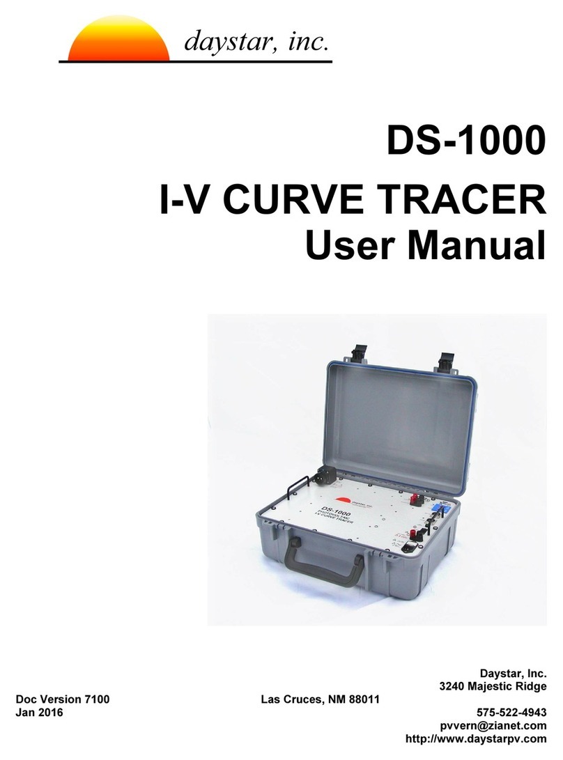
DayStar DS-100c User manual

DS-100C
I-V CURVE TRACER
User Manual
Daystar, Inc.
3240 Majestic Ridge
Version 6.02 Las Cruces, NM 880
November 20 575-522-4943
http://www.daystarpv.com
daystar, inc.
daystar, inc.
daystar, inc.
E n e r g y E n g i n e e r i n g

This I-V curve tracer was built to Daystar, Inc. specifications by:
Raydec, Inc.
82 0 La Mirada, Suite 700
Albuquerque, New Mexico 87 09

DS-TRACER Operating Manual page i
CONTENTS
CONTENTS ................................................................................................................................. i
WARNINGS ................................................................................................................................. iv
NOMENCLATURE ....................................................................................................................... v
.0 Installation & Taking IV Curves ........................................................................................
Basic Description ...................................................................................................... 1
IVPC Installation ....................................................................................................... 2
Precautions ............................................................................................................... 2
Connecting Your Computer to the DS-Tracer .......................................................... 3
Connecting a PV Mo ule to the DS-Tracer .............................................................. 3
Starting IVPC ............................................................................................................ 4
Taking an I-V Curve .................................................................................................. 5
If You Get an Error .................................................................................................... 9
Displaying Save Curves .......................................................................................... 10
Summary of Steps for Taking IV Curves .................................................................. 11
2.0 Panel Layout ....................................................................................................................... 2
Pre-Charge Fuse ...................................................................................................... 13
PV & Voltage Sense Connectors .............................................................................. 13
DISCONNECT Switch .............................................................................................. 13
Voltage Range Switch............................................................................................... 14
AC Power Entry & Fuse ............................................................................................ 15
ON-Off Switch ........................................................................................................... 15
Full Charge In icator ................................................................................................ 15
Aux Charge Power & Fuse ....................................................................................... 16
RS-232 Serial Port .................................................................................................... 16
Main USB Port .......................................................................................................... 16
Aux USB Port ............................................................................................................ 16
Irra iance Inputs ....................................................................................................... 17
Thermocouple Inputs ................................................................................................ 17
Aux Analog Inputs ..................................................................................................... 17

page ii DS-TRACER Operating Manual
3.0 Theory of Operation ........................................................................................................... 8
4.0 Maintenance ....................................................................................................................... 2
Battery Charging an Care ....................................................................................... 21
Exterior Cleaning ...................................................................................................... 22
Transportation ........................................................................................................... 23
DS-Tracer Fuses ...................................................................................................... 23
5.0 Pre-Charge Precautions .................................................................................................... 24
6.0 DS- 00C Additional Capabilities ....................................................................................... 25
Temperature & Irra iance Inputs .............................................................................. 25
Temperature Connections.................................................................................. 25
Irra iance Connections ...................................................................................... 25
Multiple Current Ranges ........................................................................................... 26
External Comman Set ............................................................................................ 26
Rea I & V “B” .................................................................................................... 27
Auto Zero I & V “Z” ............................................................................................. 27
Pre-Curve “E” ..................................................................................................... 28
Rea Analog Input “R”........................................................................................ 29
PV V & I Scales Factors “S” ............................................................................... 31
Take I-V Curve “T” ............................................................................................. 33
Rea DS-Tracer Version “V” .............................................................................. 33
Get Information “G” ............................................................................................ 34
Disable Power Down “W” ................................................................................... 36
Enable Power Down “P” ..................................................................................... 36
Transfer Curve Data “X” ..................................................................................... 36
7.0 Troubleshooting ................................................................................................................. 38
Appendix A IV Curve ASCII File Format ................................................................................. 39
Appendix B DS-Tracer ERROR CODES ................................................................................ 40
Appendix C DS- 00 USB Drivers ........................................................................................... 42
Appendix D - DS- 00C Technical Specifications .................................................................... 44

DS-TRACER Operating Manual page iii
PV Voltage Measurements ....................................................................................... 44
PV Current Measurements ....................................................................................... 44
RANGE switch settings ............................................................................................. 44
Temperature Measurement ...................................................................................... 44
Irra iance Measurement ........................................................................................... 44
Power Supply ............................................................................................................ 45
Loa Capacitors ........................................................................................................ 45
Approximate Size & Weight ..................................................................................... 45

page iv DS-TRACER Operating Manual
WARNINGS
THE IMPROPER USE OF THIS INSTRUMENT CAN PRESENT AN
ELECTRICAL SHOCK HAZARD THAT CAN CAUSE DEATH OR
SERIOUS INJURY.
THIS INSTRUMENT SHOULD ONLY BE USED AS DESCRIBED IN THIS
OPERATIONS MANUAL.
***
WARNING THIS INSTRUMENT MAY PRESENT AN ELECTRICAL SHOCK
HAZARD WHICH CAN RESULT IN DEATH OR SERIOUS INJURY IF THE
FOLLOWING PRECAUTIONS ARE NOT FOLLOWED:
• THIS INSTRUMENT MUST ONLY BE USED FOR TAKING ELECTRICAL CURRENT
AND VOLTAGE (I-V) CURVES OF PHOTOVOLTAIC (PV) SOLAR MODULES.
• THIS INSTRUMENT MUST NOT BE USED BEYOND ITS OPERATING RANGE.
• THIS INSTRUMENT MUST NOT BE USED BY PERSONNEL WHO DO NOT HAVE
EXPERIENCE HANDLING HIGH VOLTAGE DC AND PHOTOVOLTAIC MODULES.
• THIS INSTRUMENT MUST NOT BE USED DURING RAIN, SNOW, SLEET, OR IN
ANY AREA OF HIGH MOISTURE SUCH AS AREAS WITH STANDING WATER OR
MUD.
• THIS INSTRUMENT MUST NOT BE USED IF IT IS NOT FUNCTIONING AS
DESCRIBED IN THIS USER MANUAL .
!

DS-TRACER Operating Manual page v
NOMENCLATURE
A Amperes or Amp
Hz Hertz
I Current
I
pk
Current at peak power
Isc Short-Circuit Current: The maximum current a photovoltaic cell can
generate with the output terminals shorted
I-V Current-Voltage
V hotovoltaic
V Voltage
V
HIGH
High voltage range < 600 Volts
V
LOW
Low voltage range < 150 Volts
Voc Open-Circuit Voltage: The maximum voltage a photovoltaic cell can
generate with the output terminals open circuited
V
pk
Voltage at peak power


DS- 00C Operating Manual IVPC Installation & Quick-Start page
1.0 Installation & Taking IV Cu ves
Basic Descripti n
The standard DS-100C Tracer has two user selectable current ranges (10 and
100 Amperes), three automatically selected oltage ranges (600, V, 60 V, and 6
Volts), two irradiance and two temperature measurement inputs. Unless
otherwise noted, this manual refers to standard DS-100C models.
Note: The three measurement oltage ranges listed here should not be confused
with the load ranges (V
HIGH
and V
LOW
) selected with the range switch.
A computer running the IVPC for Windows program controls the DS-Tracer.
(See the IVPC Reference Manual). The computer running the IVPC application
may be connected to the DS-Tracer by RS-232 serial or USB.
Most DS-Tracer operations are performed with the IVPC program. Refer to the
IVPC manual for details on operating the DS100C IV Tracer. Howe er, the basic
steps for using the DS-Tracer are:
• Connect the DS-Tracer to the computer (either RS-232 or USB).
• Turn on the tracer power and connect DS-Tracer test leads to V array.
• Connect pyranometers and thermocouples to DS-Tracer.
• Install and run IV C for Windows (see the IV C manual for details).
• From File menu select New I-V Curve.
• Enter curve information and take curve.
• Save curve data.
To proceed with the Installation & Quick-Start, you will need the following:
• DS-Tracer I-V curve tracer and test leads.
• IV C CD-ROM.
• C computer running the Microsoft Windows® operating system.

page 2 IVPC Installation & Quick-Start DS- 00C Operating Manual
• Serial or USB cable to connect your computer to the DS-Tracer.
IVPC Installati n
IVPC is written for use with Windows® 98/2000/XP which must be running to
operate IVPC. To install IVPC, insert the IVPC CD-ROM in your computer. Open
the IVPC CD-ROM and run the “setup.exe” program by double click with the
mouse.
The setup program will prompt you for information on where you want to install
IVPC. If you are unsure, use the defaults which create an IVPC sub-directory off
of the root directory on dri e C:. IVPC Setup automatically installs the necessary
files in the IVPC directory and makes additions to your Windows system
directory.
Precauti ns
There are se eral precautions to obser e before using the DS-Tracer and IVPC
to take I-V cur es.
• The DS-Tracer battery should be fully charged. The DS-100C has a universal
power supply that works with AC line voltages from 85 V
ac
to 264 V
ac
50/60 Hz.
• The DS-Tracer DISCONNECT switch should be in the OFF position and the DS-
Tracer power should be turned on when making or breaking connections to a V
system or when changing the voltage range switch.
• The DS-Tracer should be connected to the V array through a V system
disconnect switch capable of interrupting the short-circuit current of the array at
peak-power voltage. This ensures that you can disconnect the DS-Tracer if a
problem occurs. Refer to the DISCONNECT switch discussion in section 2.0
anel Layout for details.
NOTE: The DS-Tracer DISCONNECT s itch is not rated to interrupt high
voltage systems producing more than five amps.
• Do not connect the DS-Tracer to anything other than an open-circuited V
system. Be sure the V array is electrically isolated from power conditioning
equipment such as charge controllers or inverters.
!

DS- 00C Operating Manual IVPC Installation & Quick-Start page 3
• Do not connect the DS-Tracer to a V system with an open-circuit voltage greater
than 600 Volts.
• Do not connect the DS-Tracer to any V system with a short-circuit current
greater than maximum for your unit (100 Amperes for a standard DS-100C).
The DS-Tracer RS-232 and USB ports, irradiance inputs, temperature inputs,
auxiliary analog inputs, and auxiliary charge inputs are all referenced to the
same electrical common inside the tracer. Therefore these devices must be
either electrically floating or referenced to the same electrical common.
Ho ever, all of these connections are electrically isolated from the PV inputs.
C nnecting Y ur C mputer t the DS-Tracer
The DS-100C IV Tracer pro ides two interfaces; an RS-232 and USB port. The
RS-232 interface uses a standard female, 9 pin connector as shown in Figure 8.
The standard USB connection is labeled “Main USB.” Either of these
connections may be used depending on the configuration of the computer
running the IVPC program. Though, only one of these ports should be connected
at a time.
Note: Special USB dri ers must be installed on the computer in order to use the
USB port. See the section Appendix C DS-100 USB Dri ers for details on
installing these dri ers.
C nnecting a PV M dule t the DS-Tracer
The DS-Tracer is connected to the PV array or module with the test leads
pro ided. Before connecting a PV module, be sure the DS-Tracer power switch
is ON and the DISCONNECT switch is in the OFF position. Plug the test lead
into the DS-Tracer being sure to match the red and black connectors. The
Voltage Sense connector is keyed and can only be inserted in one way.
For safety, it is recommended that connections be made to a circuit that can
be isolated from the PV array ith a system s itch rated at full PV po er.
Refer to section 2.0 Panel Layout for details.
!
!

page 4 IVPC Installation & Quick-Start DS- 00C Operating Manual
With the DS-Tracer DISCONNECT switch still OFF, attach the test leads to your
PV module. By making connections with the PV system disconnect switch off,
the chance of electric shock is a oided. After connecting the test leads, close the
PV system switch. At this point, PV oltage should be present at the DS-Tracer.
Turn the DS-Tracer DISCONNECT switch to ON. Note: For normal operation,
the DS-Tracer DISCONNECT switch should always be the last switch closed and
the first switch opened.
Starting IVPC
The following description assumes the use of IVPC 2.X. IVPC opens to the Data
Grid window shown in Figure 1. IVPC Data Grid window.. The Data Grid is a
spread sheet that lists all of the I-V cur e data files stored in the current
directory. When starting IVPC for the first time the Data Grid may be empty if no
I-V cur es ha e been taken.
Figure . IVPC Data Grid window.
The Data Grid can be thought of as a detailed directory of the I-V cur es.
Howe er, in addition to file names, you can display other cur e data such as
peak-power or module ID. Refer to the IVPC Reference Manual for directions for
changing the data displayed. Use the Data Grid to locate and display I-V cur es
that were taken pre iously and stored.

DS- 00C Operating Manual IVPC Installation & Quick-Start page 5
Taking an I-V Curve
Before taking a cur e, the DS-Tracer should be turned on and connected to the
PV system. Your computer should be connected to the DS-Tracer and running
IVPC. From the File menu, shown in Figure 2, select New I-V Cur e or press
Ctrl-N (control and N keys at the same time).
Figure 2. Select New Curve in the File menu to take an I-V curve.
Note: Some figures sho n in this manual may be different than your version
of IVPC. Please refer to the IVPC manual for the most up-to-date information
on using IVPC..
!

page 6 IVPC Installation & Quick-Start DS- 00C Operating Manual
IVPC will open a new cur e window as shown in Figure 3. This window pro ides
areas to enter cur e information identifying the I-V cur e. The DS-Tracer takes
up to 12 seconds to initialize the tracer hardware. Typically you will enter cur e
data during this delay. For example, if not using the Auto feature to read an
irradiance or temperature channel, you could enter a alue manually at this time.
A status message indicating that the DS-Tracer is pre-charging is displayed in
the area normally used to plot the cur e.
Figure 3. New Curve screen while DS-Tracer is pre-charging.

DS- 00C Operating Manual IVPC Installation & Quick-Start page 7
After initialization, the status message changes and the Take Cur e button is
enabled as shown in Figure 4. The status message indicates that a cur e can be
taken by using the mouse to press the Take Cur e button or by pressing Alt-T.
Figure 4. DS-Tracer is pre-charged and ready to immediately take the curve.

page 8 IVPC Installation & Quick-Start DS- 00C Operating Manual
After pressing Take Cur e, the DS-Tracer takes approximately 6 seconds to take
the cur e and plot the data as shown in Figure 5. You may sa e this data by
selecting Sa e I-V Cur e from the File menu. The cur e is stored in the current
directory and the Data Grid is updated.
Figure 5. Example of I-V curve.

DS- 00C Operating Manual IVPC Installation & Quick-Start page 9
You can return to the Data Grid without closing the cur e window by using the Window
menu shown in Figure 6. Closing the I-V cur e window will also return you to the Data
Grid window.
Figure 6. Moving to the Data Grid with the Window menu.
If Y u Get an Err r
There are se eral error messages you may see when taking a cur e. The DS-
Tracer automatically turns itself off when it does not recei e a command for 15
minutes. This features helps to protect the DS-Tracer battery. If the DS-Tracer
has been on for more than 15 minutes without taking a cur e it will power down
and you will recei e an error indicating that the DS-Tracer does not respond.
Simply turn the DS-Tracer switch off, wait se eral seconds, and turn it back on.
Allow the tracer approximately 10 seconds to initialize. Then pressYes to retry
as indicated on the error dialog box.
Other errors occur if the PV array oltage is too high or if it is zero or negati e.
Simply follow the IVPC directions gi en when the error occurs. Most errors
happen as soon as you chose New I-V Cur e from the File menu. Most often you
can correct the problem and continue without ha ing to restart.
The most common problem results from a communication error. This is usually
due to not setting the correct COM port in IVPC. The COM port settings must
match the actual COM port on your computer. Note: If the COM port is a “ irtual”

page 0 IVPC Installation & Quick-Start DS- 00C Operating Manual
COM port, such as those created by USB to serial adapters or by the DS-100C
USB dri ers used for IVPC ersion 2.X and older, it is possible that this COM
port number has been inad ertently changed.
Use the Windows de ice manager to confirm the current COM port setting of the
irtual COM port. The COM port number set for this irtual port must match the
COM port number set in IVPC.
Displaying Saved Curves
Stored I-V cur es are selected from the Data Grid. The Data Grid displays the
cur e files in the current directory. Be sure to set the current working directory to
the sub-directory where the cur es are stored. Use the Change Directory
command in the File menu to select a new directory as shown in Figure 7.
To display a cur e shown on the Data Grid, double click anywhere on the row for
that cur e. A window ery similar to the one used to take a cur e is displayed.
More than one cur e window may be open at the same time. Use the Window
menu to return to the Data Grid and select another cur e. The Window menu is
also used to switch between cur e windows.
Figure 7. Change Directory dialog box.

DS- 00C Operating Manual IVPC Installation & Quick-Start page
Summary f Steps f r Taking IV Curves
1. Connect your computer to the DS-Tracer and start IV C for. Turn the power
switch of the DS-Tracer ON.
2. You can connect one or two pyranometers directly to the DS-100C. If
pyranometers are connected you must enter correct pyranometer constants in
IV C. Refer to the IV C manual for details.
3. You may connect one or two thermocouples directly to the DS-100C Refer to the
IV C manual for details.
4. Open the V array system switch to isolate the V array under test. NEVER try
to take a curve of a V array connected to a battery or inverter.
5. With the DS-Tracer DISCONNECT switch in the OFF position, connect the V
system to the DS-Tracer front panel using the leads provided. (Red is positive,
black is negative.) lug the red and black leads and the voltage sense plug into
the mating connectors on the DS-Tracer; then connect the negative lead to the
V array followed by the positive red lead. Be sure to connect the tracer to the V
system through a system disconnect switch rated for Isc and Voc. Refer to the
discussion of the DISCONNECT switch in the section 2.0 anel Layout.
6. Set the voltage-range switch to the desired setting, V
LOW
or V
HIGH
. Leave the
voltage-range switch in the VHIGH position unless taking a curve of a high current
(> 50 Amperes), low voltage (< 24 Volts) V array.
7. Turn the DS-Tracer DISCONNECT switch to the ON position. The DS-Tracer is
now ready to take I-V curves.
8. From the File menu in IV C select “New I-V Curve”.
9. To take another I-V curve of the same V system, repeat step 9.
To test another V subsystem, turn the DS-Tracer DISCONNECT switch to OFF
and open the V system disconnect switch. Remove the cables and repeat steps
5 through 9.
WARNING: Disconnecting cables hen the array disconnect s itch is ON may
result in electrical arcing and may damage the DS-Tracer and/or injure the
operator.
10. When finished taking curves, turn the DS-Tracer DISCONNECT switch to the
OFF position and open the V system disconnect switch. Disconnect the DS-
Tracer from the V system. Remove the positive, red lead first followed by the
negative lead.
11. Switch off the power to the DS-Tracer.
!

page C 2 DS- 00C Operating Manual
2.0 Panel Layout
This section describes the DS-100C photo oltaic I-V cur e tracer in more detail.
The DS-Tracer generates a complete current- oltage (I-V) cur e that
characterizes the photo oltaic system under test. Figure 8 shows the front panel
layout of the DS-100C. Each of the key components is described in detail in the
following section.
TEMP #2
TEMP #1
RS-232
AUX CH ARGE
!
25V DC
IRRADIANCE #2
IRRADIANCE #1
1/4 A, 25 0V
FAST FUSE
600V DC
!
!
PV
1 A, 25 0V
SL OW FUS E
50/60 H z
85 - 264 V AC
P WER
2 A, 250V
FAST FUSE
MAIN USB
AUX USB
!
V
L W
!
V
HIGH
PRECHARGE
RANGE
DISCONNECT
V LTAGE
SENSE
daystar, inc.
Manufacturedby R ayde c,Inc., Albuquerque, NM
E N E R G Y E N G I N E E R I N G
days tar
days tar
FULL
CHARGE
TURN DISC NNECTS WITCH F F
BEF RE C NNECTING R
DISC NNECTING PV ARRAY
TURN DISC NNECTS WITCH
F FBEF RE CHANGING
V LTAGE RANGE
DS-100C
PHOTOVOLTAIC
I-V C U RVE T R ACER
AUX INPU T
11
9
8
7
6
5
4
3
117
13
10
2
16 15
14
12
1. Pre-Charge Fuse (if present) 10. On-Off S itch
2. Voltage Sense Connector 11. Full-Charge Indicator
3. Positive PV System Connector 12. AUX USB Port
4. Negative PV System Connector 13. Main USB Port
5. Disconnect S itch 14. Thermocouple Inputs
6. Voltage Range S itch 15. RS-232 Serial Port Connector
7. AC Supply Input & Fuse 16. AUX Analog Inputs
8. DC Supply Input 17. Irradiance Inputs
9. DC Supply Input Fuse
Figure 8. Face plate of the DS-Tracer.
Table of contents
Other DayStar GPS manuals
