DayStar DS-1000 User manual
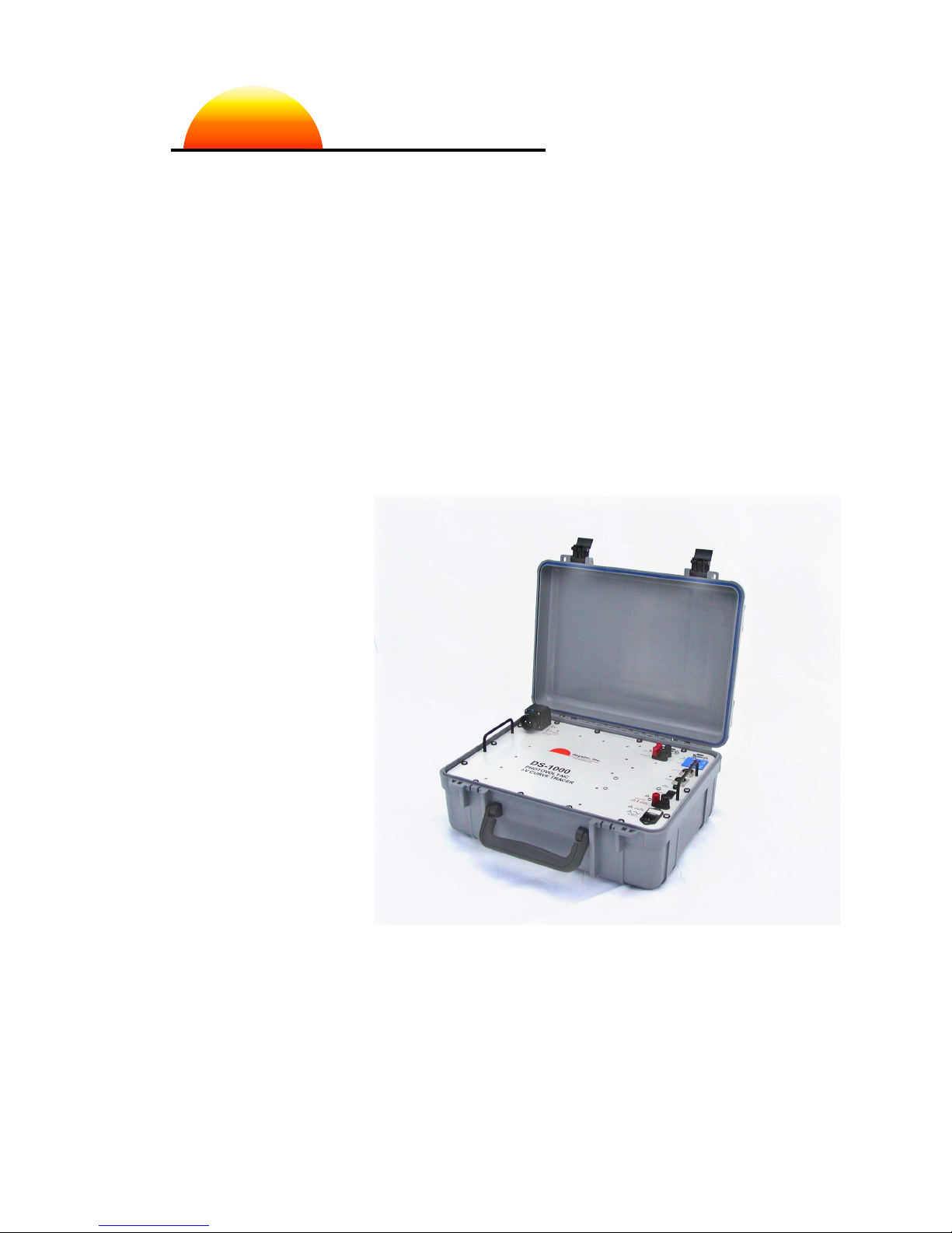
DS-1000
I-V CURVE TRACER
User Manual
Daystar, Inc.
3240 Majestic Ridge
Doc Version 7100 Las Cruces, NM 011
Jan 2016 575-522-4943
http://www.daystarpv.com
daystar, inc.

This I-V curve tracer was built to Daystar, Inc. specifications by:
Raydec, Inc.
82 0 La Mirada, Suite 700
Albuquerque, New Mexico 87 09

DS-1000 Operating Manual page i
CONTENTS
CONTENTS ................................................................................................................................. i
WARNINGS ................................................................................................................................. iii
NOMENCLATURE ....................................................................................................................... iv
1.0 Installation & Taking I-V Curves ....................................................................................... 5
Basic Description ...................................................................................................... 5
IVPC Installation ....................................................................................................... 6
Precautions ............................................................................................................... 6
Connecting a Computer to the DS-Tracer ................................................................ 7
Connecting a PV Module to the DS-Tracer .............................................................. 7
Starting IVPC ............................................................................................................
Taking an I-V Curve .................................................................................................. 9
If There Is an Error ................................................................................................... 13
Displaying I-V Curves ............................................................................................... 13
Summary of Steps for Taking I-V Curves ................................................................. 14
2.0 Panel Layout ....................................................................................................................... 15
PV Test Lead Connector .......................................................................................... 16
AC Power Entry & Fuse ............................................................................................ 16
DC Supply Input & Fuse ........................................................................................... 17
ON-Off Switch ........................................................................................................... 17
Full Charge Indicator ................................................................................................ 17
Aux USB Port ............................................................................................................ 17
Main USB Port .......................................................................................................... 1
Thermocouple Inputs ................................................................................................ 1
RS-232 Serial Port .................................................................................................... 1
Aux Analog Inputs ..................................................................................................... 19
Irradiance Inputs ....................................................................................................... 19

page ii DS-1000 Operating Manual
3.0 Theory of Operation ........................................................................................................... 20
Data Sampling .......................................................................................................... 20
Curve Sweep ............................................................................................................ 21
Pre-Charge ............................................................................................................... 21
Sweep Speed............................................................................................................ 21
4.0 Maintenance ....................................................................................................................... 23
Battery Charging and Care ....................................................................................... 23
Exterior Cleaning ...................................................................................................... 24
Transportation ........................................................................................................... 24
DS-Tracer Fuses ...................................................................................................... 25
5.0 Pre-Charge Precautions .................................................................................................... 26
6.0 DS-1000 Additional Capabilities ....................................................................................... 27
Temperature & Irradiance Inputs .............................................................................. 27
Temperature Connections.................................................................................. 27
Irradiance Connections ...................................................................................... 27
Aux Input Connections ....................................................................................... 2
Multiple Current Ranges ........................................................................................... 29
External Command Set ............................................................................................ 29
7.0 Troubleshooting ................................................................................................................. 30
Appendix A DS-Tracer ERROR CODES ................................................................................ 31
Appendix B DS-1000 USB Drivers ......................................................................................... 33
Appendix C - DS-1000 Technical Specifications ..................................................................... 35
Measurement Accuracy ............................................................................................ 35
PV Voltage Accuracy .......................................................................................... 35
PV Current Accuracy .......................................................................................... 35
Irradiance and Aux Input Accuracy .................................................................... 35
Temperature Accuracy ....................................................................................... 35
General Specifications .............................................................................................. 36

DS-1000 Operating Manual page iii
WARNINGS
THE IMPROPER USE OF THIS INSTRUMENT CAN PRESENT AN
ELECTRICAL SHOCK HAZARD THAT CAN CAUSE DEATH OR
SERIOUS INJURY.
THIS INSTRUMENT SHOULD ONLY BE USED AS DESCRIBED IN THIS
OPERATIONS MANUAL.
***
WARNING THIS INSTRUMENT MAY PRESENT AN ELECTRICAL SHOCK
HAZARD WHICH CAN RESULT IN DEATH OR SERIOUS INJURY IF THE
FOLLOWING PRECAUTIONS ARE NOT FOLLOWED:
• THIS INSTRUMENT MUST ONLY BE USED FOR TAKING ELECTRICAL CURRENT
AND VOLTAGE (I-V) CURVES OF PHOTOVOLTAIC (PV) SOLAR MODULES.
• THIS INSTRUMENT MUST NOT BE USED BEYOND ITS OPERATING RANGE.
• THIS INSTRUMENT MUST NOT BE USED BY PERSONNEL WHO DO NOT HAVE
EXPERIENCE HANDLING HIGH VOLTAGE DC AND PHOTOVOLTAIC MODULES.
• THIS INSTRUMENT MUST NOT BE USED DURING RAIN, SNOW, SLEET, OR IN
ANY AREA OF HIGH MOISTURE SUCH AS AREAS WITH STANDING WATER OR
MUD.
• THIS INSTRUMENT MUST NOT BE USED IF IT IS NOT FUNCTIONING AS
DESCRIBED IN THIS USER MANUAL .
!

page iv DS-1000 Operating Manual
NOMENCLATURE
A Amperes or Amp
Hz Hertz
I Current
I
pk
Current at peak power
Isc Short-Circuit Current: The maximum current a photovoltaic cell can
generate with the output terminals shorted
I-V Current-Voltage
V hotovoltaic
V Voltage
Voc Open-Circuit Voltage: The maximum voltage a photovoltaic cell can
generate with the output terminals open circuited
V
pk
Voltage at peak power

DS-1000 Operating Manual Additional Capabilities page 5
1.0 Installation & Taking I-V C rves
Basic Descripti n
The standard DS-1000 Tracer has three user selectable current ranges (1, 10
and 100 Amperes), three automatically selected voltage ranges (10, 100, and
1000 Volts), t o irradiance and t o temperature measurement inputs. Unless
other ise noted, this manual refers to standard DS-1000 models.
A computer running the IVPC for Windo s program controls the DS-Tracer. The
computer running the IVPC application may be connected to the DS-Tracer by
RS-232 serial or USB.
Most DS-Tracer operations are performed ith the IVPC program. Refer to the
IVPC help system for details on operating the DS-1000 I-V Tracer. Ho ever, the
basic steps for using the DS-Tracer are:
• Install and run IV C for Windows.
• Connect the DS-Tracer to the computer (either RS-232 or USB).
• Connect pyranometers and thermocouples to DS-Tracer.
• Turn on the tracer power and connect DS-Tracer test leads to V array.
• From the “Curve” menu, select New I-V Curve or press the “New Curve” button on
the toolbar.
• Enter curve information.
• ress the “Take Curve” button when ready to sweep the I-V curve.
• IV C automatically displays the I-V curve and adds it to the IV C worksheet.
To proceed ith the Installation & Quick-Start, the follo ing are needed:
• DS-Tracer I-V curve tracer and test leads.
• IV C CD-ROM or IV C download from www.daystarpv.com
• C computer running the Microsoft Windows® operating system (X through 8).
• Serial or USB cable to connect a computer to the DS-Tracer.

page 6 Installation & Taking I-V Curve DS-1000 Operating Manual
IVPC Installati n
IVPC is ritten for use ith Windo s® XP through 8 hich must be running to
operate IVPC. To install IVPC, insert the IVPC CD-ROM in the computer. Open
the IVPC CD-ROM (or alternately IVPC files do nloaded from
.daystarpv.com) and run the “setup.exe” program.
The setup program prompts for information on here to install IVPC. If unsure,
use the defaults, hich create an IVPC sub-directory ithin the Windo s
programs folder. IVPC Setup automatically installs the necessary files in the
IVPC directory and makes additions to the Windo s system directory.
Precauti ns
There are several precautions to observe before using the DS-Tracer.
• Keep the DS-Tracer battery charged. The DS-1000 has a universal power supply
that works with AC line voltages from 85 V
ac
to 264 V
ac
50/60 Hz.
• Turn the DS-Tracer power on when making or breaking connections to a V
system.
• Connect the DS-Tracer to the V array through a V system disconnect switch
capable of interrupting the short-circuit current of the array at peak-power voltage.
This allows disconnecting the DS-Tracer from the V system if a problem occurs.
• Do not connect the DS-Tracer to anything other than an open-circuit, V system.
Be sure the V array is electrically isolated from power conditioning equipment
such as charge controllers or inverters.
• Do not connect the DS-1000 Tracer to a V system with an open-circuit voltage
greater than 1000 Volts.
• Do not connect the DS-Tracer to any V system with a short-circuit current
greater than maximum 100 Amperes for a standard DS-1000.
The DS-Tracer RS-2 2 and USB ports, irradiance inputs, temperature inputs,
auxiliary analog inputs, and auxiliary charge inputs are all referenced to the
same electrical common inside the tracer. Therefore these devices must be
either electrically floating or referenced to the same electrical common.
Note: All of these connections are electrically isolated from the PV inputs.
!
DS-1000 Operating Manual Additional Capabilities page 7
C nnecting a C mputer t the DS-Tracer
The DS-1000 I-V Tracer provides t o interfaces; an RS-232 and USB port. The
RS-232 interface uses a standard female, 9 pin connector located on the DS-
Tracer front panel. The standard USB connection is labeled “Main USB.” Use
either of these connections depending on the configuration of the computer
running the IVPC program. Ho ever, only one of these ports should be
connected at a time.
Note: Special USB drivers must be installed on the computer in order to use the
USB port. See the section “Appendix B DS-1000 USB Drivers” for details on
installing these drivers.
C nnecting a PV M dule t the DS-Tracer
The DS-Tracer is connected to the PV array or module ith the test leads
provided. Before connecting a PV module, be sure the DS-Tracer po er s itch
is ON. The test lead is designed to remain connected to the DS-Tracer at all
times. It is typically unnecessary to remove this from the tracer.
For safety, the test lead should never be disconnected from the tracer while
the other end is connected to a PV system. Doing so could present an electric
shock hazard.
For safety, it is recommended that connections be made to the PV array
through a system disconnect switch rated at full PV power.
With the test lead attached to the DS-Tracer, connect the test leads to the PV
system.
!
!
page Installation & Taking I-V Curve DS-1000 Operating Manual
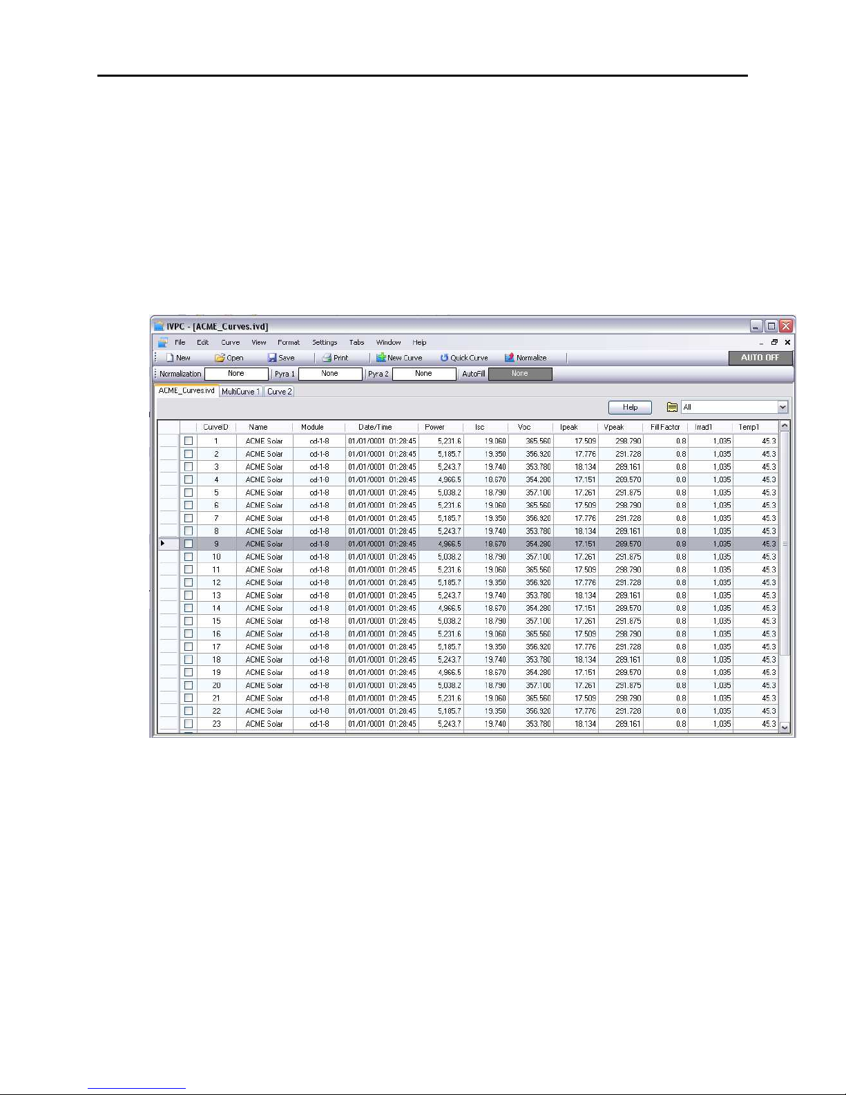
Starting IVPC
The follo ing description assumes the use of IVPC 3. IVPC opens to the Data
Grid indo sho n in Figure 1. IVPC Data Grid indo .. The Data Grid is a
spread sheet that lists all of the I-V curve data files stored in the I-V curve
orksheet. When starting IVPC for the first time, the Data Grid may be empty if
no I-V curves have been taken.
Figure 1. IVPC Data Grid window.
The Data Grid is as a detailed list of the I-V curves. In addition to curve names,
the data grid displays other curve data such as peak-po er or module ID. Refer
to the IVPC Help system for details.
DS-1000 Operating Manual Additional Capabilities page 9
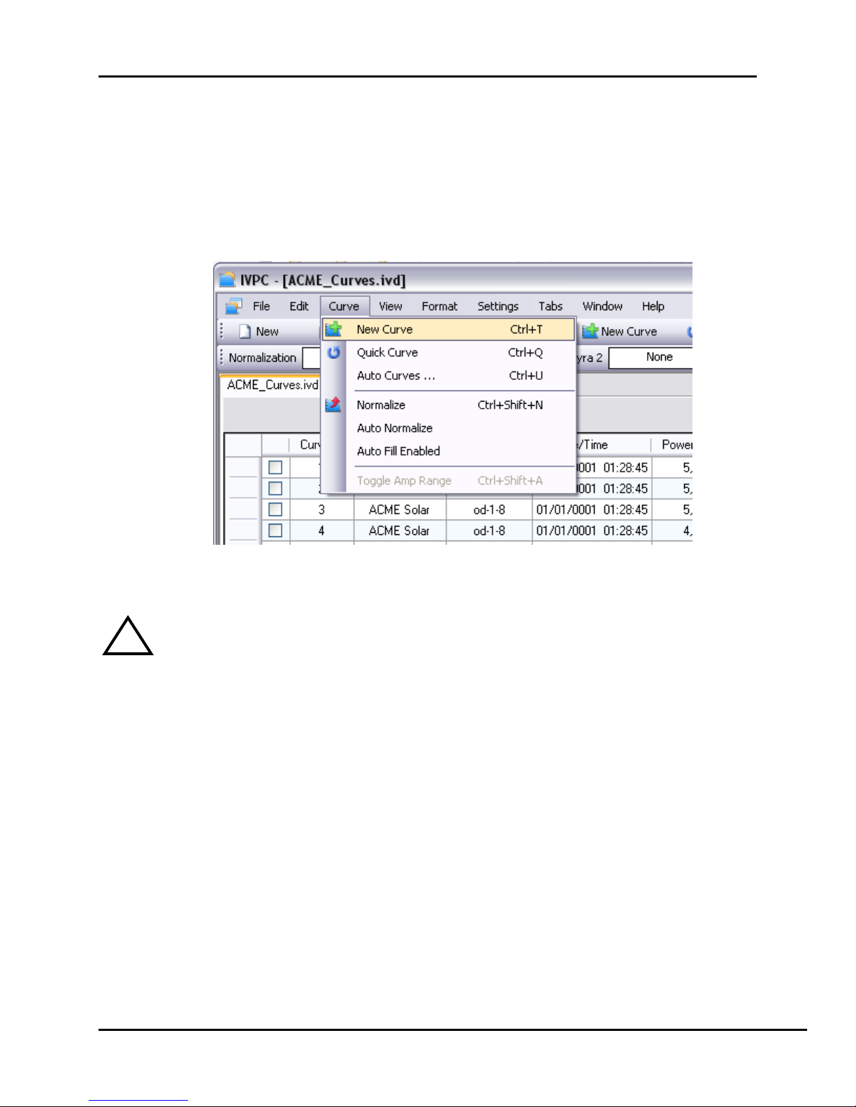
Taking an I-V Curve
Before taking a curve, turn on the DS-Tracer and connect it to the PV system.
Connect the computer running IVPC to the DS-Tracer. From the “Curve” menu,
sho n in Figure 2, select “Ne Curve” or press Ctrl-T.
Figure 2. Select “New Curve” in the “Curve” menu to take an I-V curve.
Note: Some figures shown in this manual may vary. Please refer to the IVPC
manual for the most up-to-date information on using IVPC.
!
page 10 Installation & Taking I-V Curve DS-1000 Operating Manual
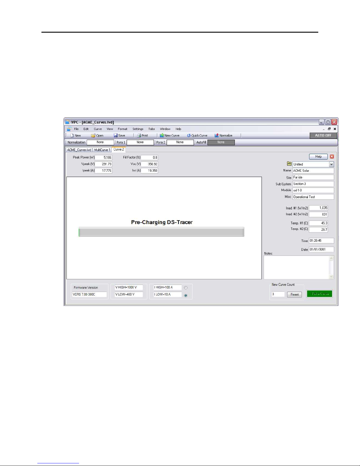
After starting a ne curve, IVPC opens a ne curve indo as sho n in Figure
3. This indo provides areas to enter curve information identifying the I-V
curve. The DS-Tracer may take several seconds to initialize the tracer hard are.
A status message indicating that the DS-Tracer is pre-charging is displayed in
the area normally used to plot the curve.
Figure 3. New Curve screen while DS-Tracer is pre-charging.
DS-1000 Operating Manual Additional Capabilities page 11
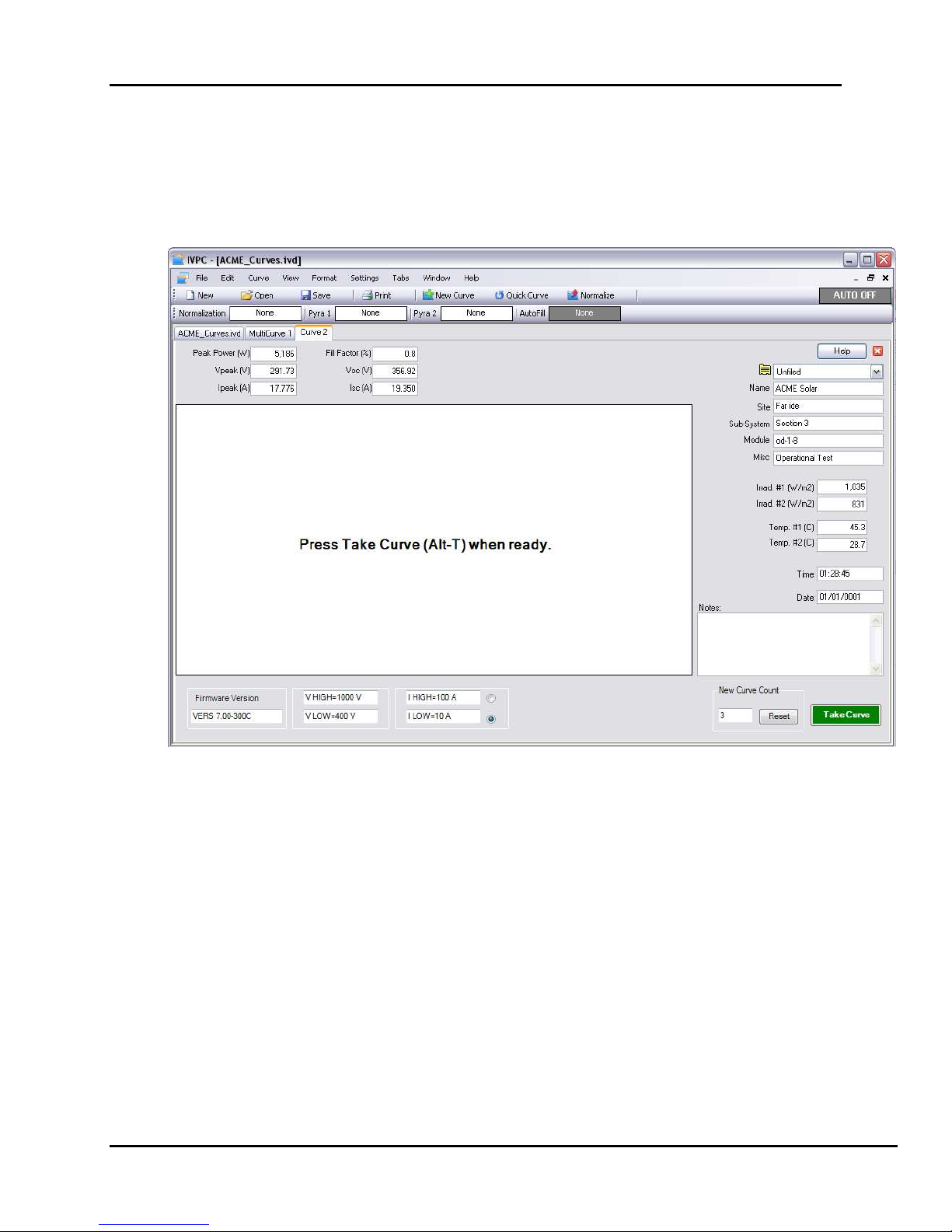
After initialization, the status message changes and the “Take Curve” button is
enabled as sho n in Figure 4. This status message indicates that a curve can be
taken by pressing the “Take Curve” button or by pressing Alt-T.
Figure 4. DS-Tracer is pre-charged and ready to immediately take the curve.
page 12 Installation & Taking I-V Curve DS-1000 Operating Manual
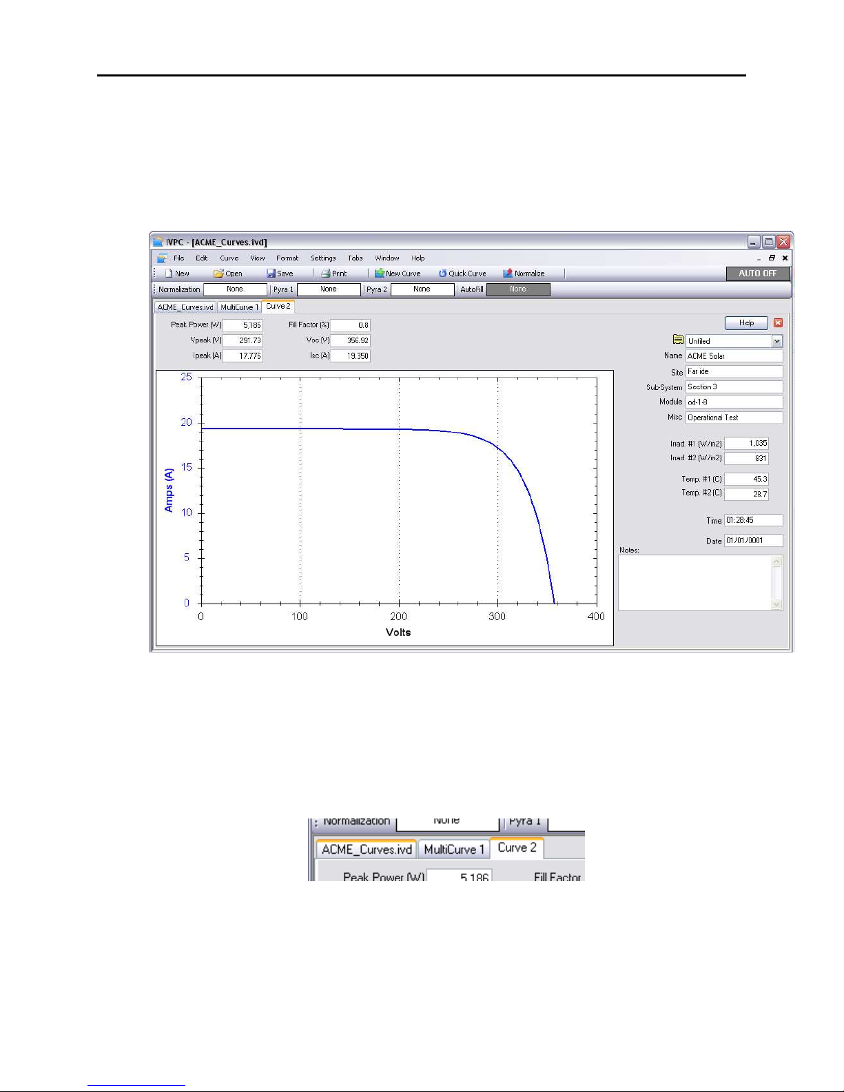
After pressing the “Take Curve” button, the DS-Tracer takes approximately 2 to
10 seconds to take the curve and plot the data as sho n in Figure 5. The ne
curve data is automatically added to the orksheet. Ho ever, the orksheet is
not automatically saved to disk.
Figure 5. Example of I-V curve.
It’s possible to return to the Data Grid, ithout closing the curve indo , by clicking on
the data grid tab (far left tab) as sho n in Figure 6. Closing the I-V curve indo also
opens the Data Grid tab.
Figure 6. Moving to the Data Grid using tabs.

DS-1000 Operating Manual Additional Capabilities page 13
If There Is an Err r
There are several error messages IVPC may display hen taking a curve. The
DS-Tracer automatically turns off hen it does not receive a command for 15
minutes. This features helps to protect the DS-Tracer battery. If the DS-Tracer
has been on for more than 15 minutes ithout taking a curve it ill po er do n
and IVPC generates an error indicating that the DS-Tracer does not respond.
Turn the DS-Tracer po er s itch off, ait several seconds, and turn it back on.
Allo the tracer approximately 10 seconds to initialize. Then retry as indicated
on the error dialog box.
Other errors occur if the PV array voltage is too high or if it is zero or negative.
Follo the IVPC directions given hen the error occurs. Most errors occur
immediately after selecting “Ne Curve” from the “Curve” menu.
The most common problem results from a communication error. Incorrect COM
port settings in IVPC may cause this problem. The COM port settings must
match the actual COM port on the computer. Note: If the COM port is a “virtual”
COM port, such as those created by USB to serial adapters or by the DS-1000
USB drivers, it is possible that this COM port number has been inadvertently
changed.
Use the Windo s device manager to confirm the current COM port setting of the
virtual COM port. The COM port number set for this virtual port must match the
COM port number set in IVPC.
Displaying I-V Curves
From the Data Grid, double click a curve to display it.
Use the “Multi-plot” feature, under the “Vie ” menu, to display multiple curves on
one plot. Several options exist for displaying I-V curves. Refer to the IVPC Help
system for details.

page 14 Installation & Taking I-V Curve DS-1000 Operating Manual
Summary f Steps f r Taking I-V Curves
1. Connect the computer to the DS-Tracer and start IV C. Turn the DS-Tracer
power switch ON.
2. Connect pyranometers to the DS-1000. If pyranometers are connected, enter
pyranometer constants in IV C. Refer to the IV C help system for details. Note:
yranometers do not need to be used to sweep an I-V curve.
3. Connect thermocouples to the DS-1000. Refer to the IV C help system for
details. Thermocouples are not required to sweep an I-V curve.
4. Connect the DS-Tracer test lead to the DS-Tracer before connecting the test lead
to the V system. Connect the red clip to V positive and the black clip to V
negative. Be sure to connect the tracer to the V system through a system
disconnect switch rated for Isc and Voc. The DS-Tracer is now ready to take I-V
curves.
5. From the “Curve” menu in IV C select “New Curve”.
6. Edit I-V curve information such as name and site as needed.
7. When ready, press the “Take Curve” button to begin the I-V sweep. The I-V curve
is displayed as soon as the curve sweep is complete.
8. To take another I-V curve of the same V system, repeat step 5-7.
To test another V subsystem, open the V system disconnect switch. Remove
the cables and repeat steps 4 and 7.
9. When finished taking curves, open the V system disconnect switch. Disconnect
the DS-Tracer from the V system.
10. Switch off the power to the DS-Tracer.

DS-1000 Operating Manual Panel Layout page 15
2.0 Panel Layo t
This section describes the DS-1000 photovoltaic I-V curve tracer in more detail.
The DS-Tracer generates a complete current-voltage (I-V) curve that
characterizes the photovoltaic system under test. Figure 7 sho s the front panel
layout of the DS-1000. Each of the key components is described in detail in the
follo ing section.
8
9
RS- 232AUX INPUT
7
TEM P #2
AUX U SB
MAIN USB
11 10
2 A, 250V
FAST FUSE
PO W ER
FULL
CHARG E
2
4
5
1 A, 250V
SLOW F USE
50/60 H
85 - 2 64 V AC
25V DC
AUX C HARG E
DS-1000
PHOTOVOLTAIC
I-V CURVE TRACER
1000V DC
!
1
PV
12
Manu fac tured by Ray dec, Inc. , Albuq uerque, N M
!
!
3
TEM P #1IR RADIANCE #1
IR RADIANCE #2
daystar, inc.
www.daystarpv.com
6
DO NOT D ISC ONN ECT
WHEN I N USE
(see ma nual)
1. PV System Connector 7. AUX USB Port
2. AC Power Entry & Fuse 8. ain USB Port
3. DC Supply Input 9. Thermocouple Inputs
4. DC Supply Input Fuse 10. RS-232 Serial Port Connector
5. On-Off Switch 11. AUX Analog Inputs
6. Full-Charge Indicator 12. Irradiance Inputs
Figure 7. Face plate of the DS-Tracer.
page 16 Panel Layout DS-1000 Operating Manual
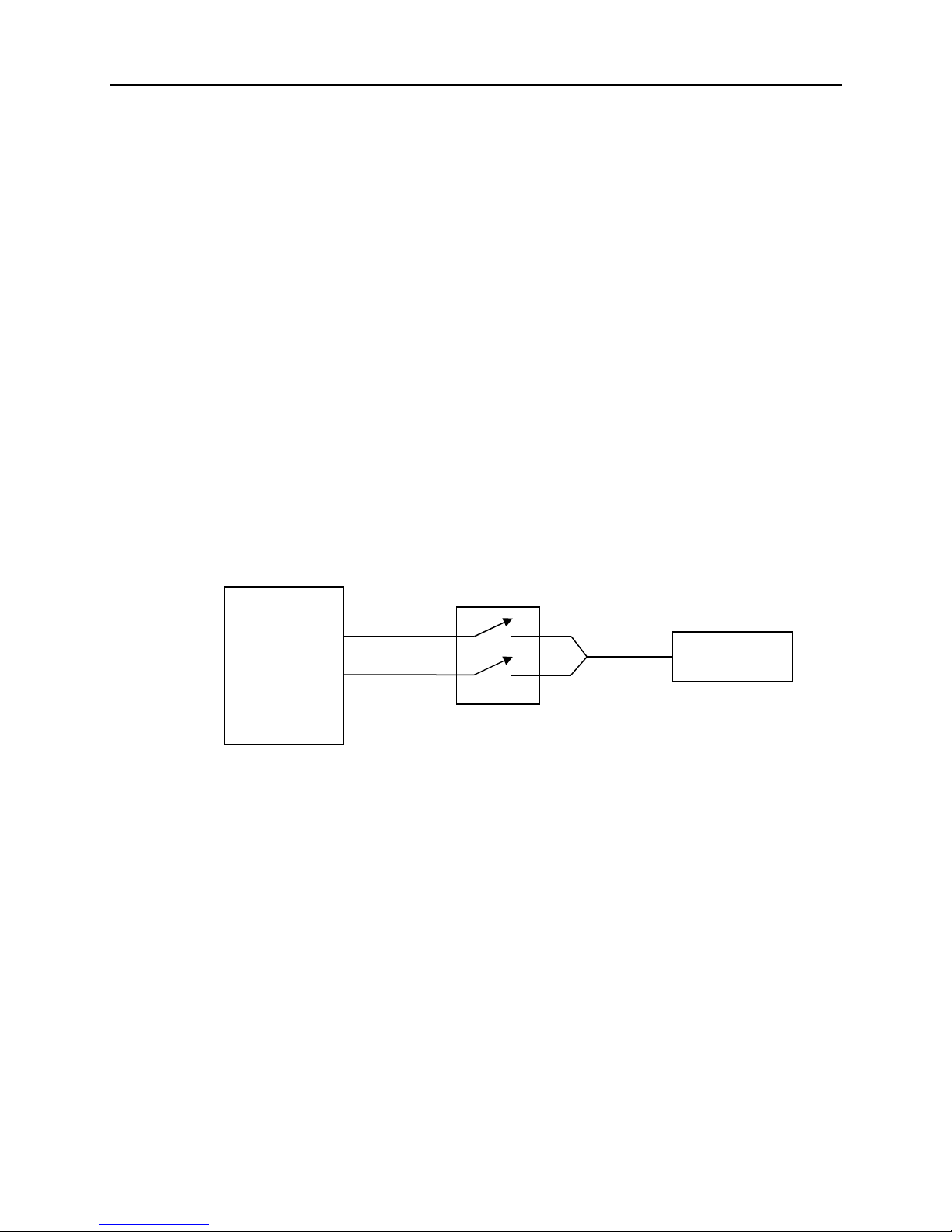
PV Test Lead C nnect r
When an I-V curve is taken, the load current flo s through the test lead into DS-
Tracer. The red and black test clips go to PV array positive and negative
terminals respectively. The test cable contains separate voltage sense ires to
measure the PV voltage at the test clips. This 4- ire measurement technique
avoids measurement errors caused by voltage drops in the test leads.
For maximum safety, the DS-Tracer should be connected through a PV system
disconnect rated at the PV system V
oc
and I
sc
values. See Figure 8. A system
disconnect s itch provides a ay to break the electrical connection should the
DS-Tracer have a major internal failure.
Figure . Use of PV system disconnect switch.
AC P wer Entry & Fuse
Connecting the DS-Tracer to an AC po er source recharges the DS-Tracer
battery. It is not necessary for the tracer to be on. Refer to section “Battery
Charging and Care” in section “4.0 Maintenance” for details of battery charging.
DS-Tracer
PV Array
System
Disconnect
Switch
Test Lead

DS-1000 Operating Manual Panel Layout page 17
DC Supply Input & Fuse
The DS-Tracer may be po ered or recharged from an external DC po er
source. This source could be a PV module. Refer to section “Battery Charging
and Care” in section “4.0 Maintenance” for details of battery charging.
ON-Off Switch
This s itch turns on the DS-Tracer po er. Turn this s itch on before
connections are made to a PV array. The curve tracer takes approximately 10
seconds to initialize after it is turned on.
The DS-Tracer automatically turns itself off if a curve has not be taken for 15
minutes. This feature protects the DS-Tracer battery. If the DS-Tracer has turned
itself off, s itch the po er s itch off, ait several seconds, and turn the s itch
back on.
Full Charge Indicat r
When this LED lights, its indicates that the DS-Tracer battery is fully charged.
When fully charged, this indicator remains on hile the DS-Tracer is plugged into
AC po er. Sometimes this LED ill turn on briefly if the AC po er cord is
unplugged before the battery is fully charged. This occurrence does not indicate
a fully charged battery.
Aux USB P rt
This port supports auxiliary DS-1000 operations This port is a standard USB
Type-A port. This port is not used to control the DS-1000 I-V tracer. It is used to
update the I-V curve tracer internal firm are. In the event that an update is
needed, the proper use of this port ill be described at that time. This port may
also be used for advanced features in future releases of DS-1000 firm are or
IVPC.

page 1 Panel Layout DS-1000 Operating Manual
Main USB P rt
All DS-Tracer operations are controlled ith commands sent to the DS-Tracer
through this USB port or the RS-232 port. This port is a standard USB Type-B
port. Normally the DS-Tracer functions are controlled ith the IVPC soft are, but
custom soft are can control the DS-Tracer using the DS-Tracer command
codes. Refer to the “DS-1000 Command Reference” manual for details.
Therm c uple Inputs
The standard model DS-1000 is configured ith t o Type “T” thermocouple
inputs for measuring PV array module temperatures. Refer to the IVPC Help
system for details on making temperature measurements and “Appendix C - DS-
1000 Technical Specifications”.
RS-232 Serial P rt
All DS-Tracer operations are controlled ith commands sent to the DS-Tracer
through this serial port or the USB port. This port is a standard 9 pin RS-232
port. This port is configured as a DCE device. Normally the DS-Tracer functions
are controlled ith the IVPC soft are, but custom soft are can control the DS-
Tracer using the DS-Tracer command codes. Refer to the “DS-1000 Command
Reference” manual for details.
The DS-Tracer uses the follo ing default RS-232 format:
9600 Baud
No parity
data bits
1 stop bit
Table of contents
Other DayStar GPS manuals


