Daystrom Heathkit IG-72 User manual

PRrCE $1.OO
..|
o
o
HEA.THKIT.
A'.SSEAITEII-Y N4A-1\TTJA,I-
GENERATOR
M()t)EL IG-72
AUDIO
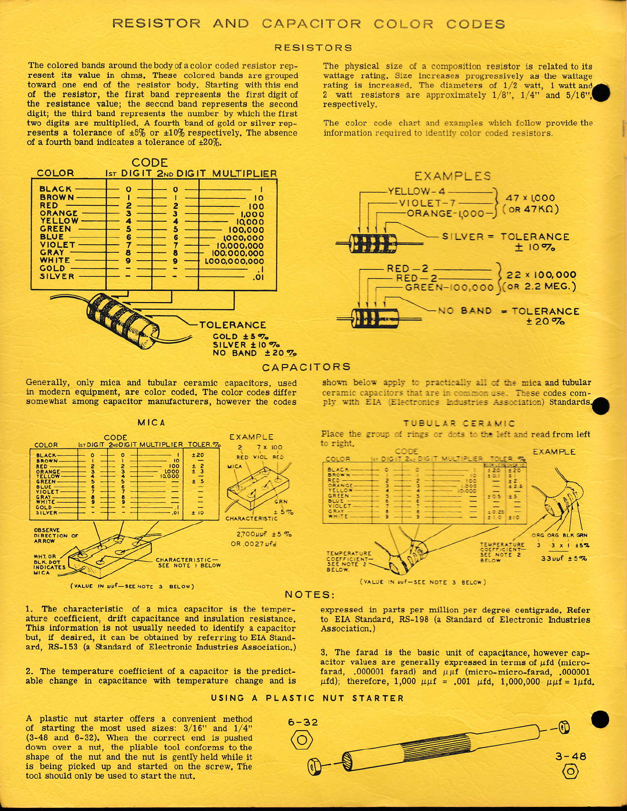
The colored banrls aroud thebodyol a color coded lesistor reD-
lesent its valu€ in ohb6. These colored beds are grouled
tovald one end oi the resistor body. Sta*ing vitn this end
ot the resisto!, $e first land relresenk the flrst.jlgit of
the resbtuce velue; the decord bald represents the second
digit; the tllild bud repreBents the nuhbe! by which the fllst
two dglts ale muri&Ued, A foufih bald oI sold or silver rep-
lesents a tolelalce ol +5% or *10% respectively. The absence
of a foulill bdd indcates a tol€luce ol d0%,
RESISTOR AND
MICA
CAPACITOR
RESISTORS COLOR CODES
The lhysical size of a cohlosition leslstor ls related to itB
vattage rating. Size increases proglessively aE the pattage
;"'ff- ",;'J*ffi :"';Jx,llxfflili, 1'r,i,/,' jill, i"-t),?'.a
The colo! code chari dd examples whieh loUow prolide the
inlortuatio! requn'ed to ldentiir coior cod€d.€sistors,
EXAMPLES
YELLOW 4_
I rO\rJ '-\
i;:;' -- ' { 47'Lcoo
lb"ni-*'ce - to oo J I oR 47^o)
SILVER = TOLERANCE
t lo70
!209o
CAPACITORS
Gene.ally, only mica ad tlbu1a! ceramic capacitors, used
in mode.n equipment. ale color coded. The color codes (Mfe!
somevhat abong capactto. Eordacturers. however the codes
shoin !:::- :!!:: :: :.::i::-: :,- :: ::: :].a and tubular
..rr.:ri :rar: i: -.. ::ij..odes com-
.l: ,::: :. ::::::::::: :.:-!:::-: ..r! ::::r::) Stsdardsa
P::.: ::: :.::: : ::r.-: :: :::: : :.!::l:::.Eadlromlelt
CODE
:"=
(v^LUr rN,er rElorE 3 6.16{)
zloo*t t sq.
USING A PLASTIC NUT STARTER
r r, *iz
1v Lr. 'i 4.-s.. NorE I 3:Lor)
exllesBed in parts ler million pe. degree centigrade. Refe!
to EIA Studard, RS-198 (a Staldard oi Electronic Ind8t.les
3. The farad i3 the basic ult ol calacitance, howeve! c.!-
acltor values are genelally e)Alessed in telhs ol pld (Eicro-
falad, ,000001 farad) &d ]lpr (nicro-micro-farad, .000001
!ld), thereiole, 1,000 girf = .001 irfd, 1,000,000 pgf = lBfd.
NOTE
1. The chalacte.ktic ol a hica capaciior is the temper-
ature coerflcieni, .lrift calacitance and insulation resislmce.
This iorolmation is not usually needed to identily a capacitor
but, u desired, it c& be obtailed by r€Ielring to EIA Sted-
ard, AS-153 (a Standald of Electronic Industries Association.)
2. The temperature coefficient oi a calacitor is the predict-
able chuge in caleituce with temperatuie chdge ud i6
A plastic nut starter oflers a convenient method
oI stadiug ihe most used sizes: 3/16" ad r/4"
(3-48 and 6-32). when the co!.ect erd is pushed
dom over a !ut, the lliable tool contolms to the
shap€ ol the nut ud th€ nut is gently held white it
is being ptcked up dd siaded otr the screw. The
tool should only be used to start tie nut.
3-4
o
CODE
Isr DIGIT 2No DlclT MULTIPLIER
TOLERANCE
NO BANO leozr
ORANOE
CFEEN
VI OLET
WHITE
GOLD
SILVER
o
I
2
3
5
6
7
a
:
o
I
2
3
5
5
7
:
rqooo
loo,ooo
toco,ooo
r.ooo,ooo.ooo
6-32
.\
-.^ -. ( 22 r TOO,OOO
E"cifru-oorooJ(oR 2 2 MEG.)
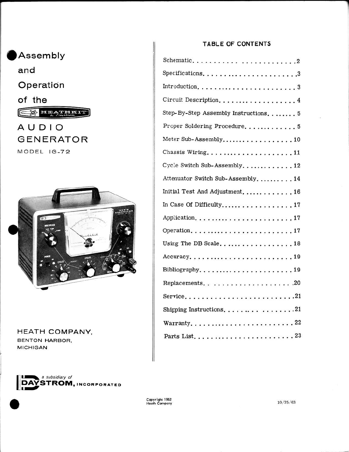
f Assembly
and
O pe ratio n
of the
AUDIO
G EN ERATOR
MODEL 1C.72
HEATH c:OMPANY,
BENTON HARBOR,
MICHIGAN
1 a subsidiaty ot
PAYSTRoM,,N
TABLE OF CONTENTS
Schematic. . .. .. ,. .2
SpeciJications.,..........,..3
Int.oduction. .....,......,.3
CircuitDescription, .........4
Step-By-Step Assembly Instructions., ..... . 5
Proper Soldering Procedure.,,..,,. .. ... 5
Metersub-Aasembly .....,,..10
Chassiswiring.,,.........11
Cycle Switch Sub-Aaaembly. . ...., . . .... 12
Attenuator Switch Sub-As8embly. ... . .. . . . 14
Iiitial Test And Adjustment........ . ... . 16
In Case Of Difiiculty ....... -.11
Application. ......17
Operation. -...-..11
Using The DB Scale, ........18
Accuracy,. ......19
Bibliography,,,.......,..,19
Replacements, .. ,... ..., .. .20
Service... ,...,..21
Shippinglnstructions ...,....21
warranty.. ......22
Parrs List, ,.-...23
10/25r63
rov
Lil
rAGEr
l(
I
I
I
I
I
SCA
VOL
16 MFD
I 50V
PrLOT 6X4 6AU6 6CL6
3V IV .3V .IV
24o.(J. 390
.o3 v.orv .oo3v
r600 r 600
il 5V -3W
LAM P
OUTPUT
O
__l_
_
20 MFD
350V 5000
20w
LOAD
SW I TCH
ATTENUATO R
I
I
I
I
47c,0 |
I
l-
f oK t/'
M ETER
CONTROL
,/T\lcz
I
_=L
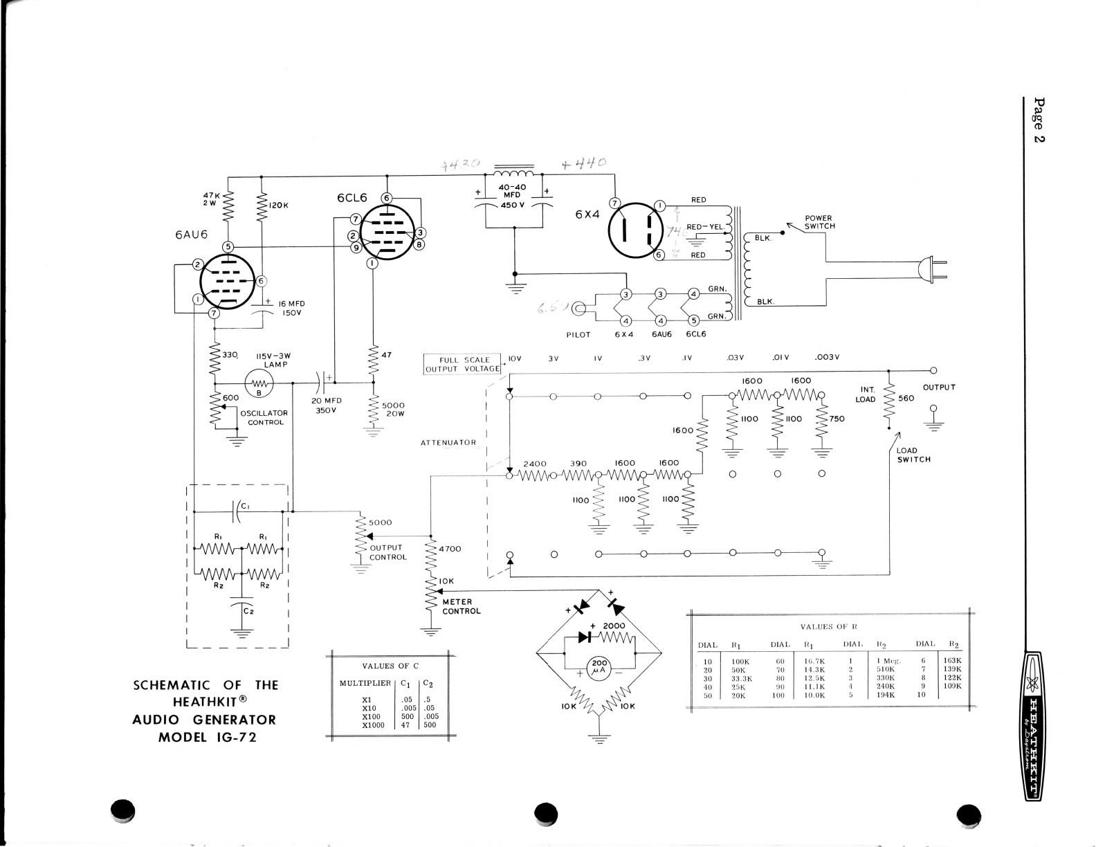
SCHEMATIC OF THE
HEATHKIT @
AUDIO GENERATOR
MODET IG-7 2
VALUES OF C
MULTIPLIERICl lcZ
xl I .0, l.t
xlo Loos l .os
xloo Isool.oos
xlooo l+t lsoo
POWER
SWITCH
FULL
OUTPUT
VAt,UES OI.' II
DIAL R1 DIAL llt l)lAl, l(2 DIAI, Il2
10
20
30
40
50
l00K (i0
50K 70
33.3K ltO
2l-rK 1)0
20K 100
I (;.7K I
14.3K 2
12.5K 3
I l.lK 4
10.0K 5
I Mcg. 6
5l0K 7
33OK B
240K I
t94K 10
lti3K
139K
l22K
109K
_l
OSCILLATOR
CONTROL
I@EEEEFT n""a
SPECIPICATIONS
Frequency Range:..... .....10 cycles - 100 kc
Tuning Method:.. ,............... Switch-selected,2 signilicant figures and multi-
plier.
Flequency Accuracy:. , . . . . , ,,,,,, ,...., ..,. +5%
Output Voltage Ranges:..... ...., , ...........0-10 volts into Hi-Z (10 KO min. )
0-3 volts into t{i-Z (10 KO min. )
0-1 volts \
0-.3 volts I Into external load of approx-
0-.1 volts ! imately 600Q or wilh inlernal
0-.03 volis I load into external Hi-2.
0-.01 volts I
o-.003 volts J
Source Impedance:.. , , . . . . . . . . . . 0 - 10 volt range - varies between 0 and 1000 O,
0-3 volt range - varies between 800 and 1000 O,
0-1 volt range and below - 600 Q (External Load)
290 r) (Internal Load)
DB Ranges:. . . . . . . . . .... -60 db to +22 db (-10 to +2 on meter. -50 to +20
on attenuator in l0 db steps).
DBll Rangea (600 O Ext. Load):. . . . . . . . . . . . . . -60 dbm to +2 dbm (0 dbm - I mw-600 f,))
O"rput Indication:. .......Voltage and db scaies on meter.
Oulput Mete! Accuracy: . . . . . , , . . . , , . . , . . . . . . +5% of full scale when properly terminated.
Distortionr, ..,.........., Le6s than 0.1q0 from 20-20,000 cycles.
Tube Complement:.. .....6X4, 6AU6 and 6CL6
Po*er Requirements:. , . .. . . . . . . . . . ..... .... 105-125 volts. 50-60 cycles, 40 watts
Dr:nensions:. . . . . . . . ..., I l/2" wide x 6 1/2" high x 5" deep
S:-rpping Weight:.... .. .. .8 lbs.
INTRODUCTION
The fieathktt Mode1 IG-72 Audlo Generator is a aimple, yet vefsetile lnstrument. lvhile simple
i'r ]ayout and easy to construct, the cer:efully assembled inatrument provldes ease of operation
in a multitude oI test setups encountered in audio laboratories. The wide range oI repeatable
irequencies and the metered Iow distortion output voltages covering nearly all values encoun-
rered in audio work contained in the conveniently small cabinet will entitle this instrument to a
preferred spot in the laboratory.
The excellent performance oI which this design is capable wiII not be realized in thefinished in-
strument, UNLESS the assembler uses the best workmanship of which he iE capable. Poor sol-
dering technique, corrosive fluxes (acid core, so-called ron-corrosive pastes), hurried and
careless constructionand failure tofollow procedures outlined inthis manual are the most pre-
valent causes for unsatislactory operation. Protect your investment in tlme and money andreap
the reward of personal satis(actionthat money cannot buy, by doing a Iirst class iob oI construct-
ing this kit.

p.e" I lii#EEl
CMCUIT DESCRIPTION
The circuit of tNs instrument may be divided into lour parts: the power supply, the oscillator,
the attenuator and the metering circuit.
The power supply uses the conventional power transformer lull wave rectilier circuit feeding a
,ipple filter consisting oI two condensers and a choke.
The oscillator uses a 6AU6 pentode voltage amplifier and a 6CL6 triode-connected cathode fol-
lower. R egene rative feedback fromthe 6CL6 tothe 6AU6 cathode is applied through thetungsten
filament candelabra based lamp-
Degenerative feedback is applied from the 6CL6
thiough a "notch" networkto the gridol the 6AU6.
The reaultant oscillation occurs at the "notchrl
frequency, where degeneration is minimum and
phase 6hift is zero.
network is a capacitor-shunted
bridged-T tlpe. The "notch" occurs at a fre-
quency: F =1
'frRE'
a
\a,he.e C =r/e-1c2
'fhe amplitude oI oscillation is maintained at a
nearly constant value by thetungsten lamp. The
regenerative feedbac k is applied through a volt-
age divider consistingof the iamp and the "oscil-
lator" control. An increase in output signal in-
creases the lamp current, the Iamptemperature
andthe lamp resistance. This reduces the amount
of leedback applied to the 6AUO cathode and the
resultant output. A balanced condition is thus obtained. The "oscillator"
control Is used to set the nominal output level.
The ,notcht! network consists basically oI two resistances and two con-
densera. From the relationship shown it is evident that a decrease in
capacitiesby a factor oI 10 willincrease the frequency by a lactor oI 10.
As the values of C1 and C2 were chosen with a 10:1 ratio, Iive conden-
6ers can do the job oi fou! pair or eight, in achievinglou! decade ranges.
f'or flequency variationwithin th€ steps oI 10 times provided by the multiplier switch, the value
of R is changed. For a multiplier switch setting oI Xl a resistance (R) of 100 KA v,/ill produce
a lrequency of l0 cycles. As F and R are inversely proportional, 20 cycles or twice the fre-
quency, requires half the lesistance, or 50 KQ- Likewise, 30 cycles or three times the fre-
quency requires l/3 the resistance or 33.3 KQ. The 0-100 "cycle" switch uses two decks, each
deckswitchingfour resistorsas lollows: 100 K0, 50 K0,33-3 K0. 25 K{1. l0O K // 25 K = 20 K;
50K // 25K = 1r'.7 K; 33.3 K // 25K = 14.3 K; r00 K // 33.3 K / 25 R = 12.5 K; 50 K // 33.3 K
//25IK=ll.1K:' l0OK // 50K //33.3K//25K= 10 K. These resistance values produce {re-
quencies of 10 to 100 cycles in steps of l0 cycles. \// means "in parallel lrith.')
L
. L______1_t__i_r ;";*,.,
\
-_
P.d- q
. !:-r-
: .quency variations within a 10 cycle spaD are produced by the 0-10 "cycle" switch. Here the
:::rereasoning andcircuitry areused as abovebut the actual resistance valuesare substantially
'- : rimes larger. These resistance values are connected in paraUel with the first switch arld
:i luce one cycle iDcrements.
: . attenuator reduces the output voltage lrom the 6CL6 cathode-Iollower through a continuously
-rrable 5 KQ "output" control, and then through a step attenuator. The attenuator system is
:.iiqned for 600 A output up tfuough 1 volt and high impedance output at the 3 and 10 volt posi-
:is. The 600 Q positions may be terminated by an internal Ioad lor high impedance work or
.iloadmay be disconnected when anexternal 600Q Ioad is used. In the 3 and 10 voltpositions,
' rnternal load is automatically disconnected. The attenuator operates in steps of 10 db.
: . metering circuit measures the voltage at the arm of the "output" control. A portion of this
.rge, determined by the "meter" control, is rectified by a half-bridge using crystal diodes.
\ rr-linearity of the diodes at Iow signal level is compensated by a third diode across the tneter.
: . meter carlies three scales: 0-10 volt, 0-3 volt, and -10 to +2 db. When the instrument is
!:r'a1ed with the proper termination, the meter and attenuator will indicate the output level at
-: rinding posts.
STEP.BY-STEP ASSEMBLY INSTRUCTIONS
i ,:rr o[ parts can be assembled into the finished product in a variety of ways; Irom pictorials,
-_. Iographsor from circuitdiagram alone. However, evenexperiencedand skilled professional
: :sons have discover:ed that a combination of pictorials and step-by-step written instructions
::: rlide the lastest, most convenient way. This also guards against the disappointment o, fail-
-:'E iooperate alter construction is completed, due to a singte minor hard-to-find omission.
::.e written assembly instructions in this manual are divided into small operations or steps.
:'.h step is a complete operation. Read the entire step through, then do that operation and
.i.k it off as completed. Alter aD interruption, it is easy to find where you left off by the
...ck marks. Read over the last checked step and you are all ready to continue.
:_ Ihe mechanical assembly, use lockwashers under all 6-32 nuts and between aII controls or
:; rtches and the mounting surface.
:: :he wiring (S) means solder this connection and (NS) means do not solder yet, as more wires
: ll be connected to this point. lI more than one wire is to be soldered at a connection point,
:-. instructions wiII appear as follows (S) (3) which means solder this connection which should
:.:-.'e three wires connected to it. This will provide a runDing check of multiple connections.
PROPER SOLDERING PROC EDURE
Or:v a small percentage of Heathkit purchasers find it
:: rrrry service. Of these, by far the Iargesi proportion
:::proper soldet'ing.
,- :re(t soldel.ing technique is extlenrelr-' impoIraDl. Good soldcr join(s ar. css{'nlial il' thc
rrriornrance engincel.ed into the kil js to be iully relljzcd. ll you ]r.. .l beginDel. wilh no ox-
!.irer)ce in soldering, a half-hour"s practice with odd loDgths oi wjr-. and a lubc so(kol will bo
., ror-thwhile investn1ent.
necessary to retuln an instrument ior
function improperly because of poor or

n.*"u @EEFI
ROSIN CORE SOLDER HAS BEEN SUPPLIED WITH THIS KIT. THIS TYPE OF SOLDER
MUST BE USED FOR ALL SOLDERING IN THIS KIT. ALL GUARANTEES ARE VOIDED
AND WE WILL NOT REPAIR OR SERVICE EQUIPMENT IN WHICH ACID CORE SOLDER
OR PASTE FLTIXES I]AVE BEEN USED. IF ADDITIONAL SOLDER XS NEEDED, BE SURE
TO PURCIIASE ROSINCORE (60i40 or 50:50 TIN- LEAD CONTENT) RADIO TYPE SOLDER.
II terminals are bright and clean and wires free of wax, frayed insulation and other foreign sub-
stances, no difliculty will be experienced in soldering. Crimp or otherwise secure the wire
(or wires) to the terminal, so that a good joint is made without relying on solder Ior physical
strength. To make a good solder joint, the clean tip of the soldering iron should be placed
against the joint to be soldered so that the terminal is heated sufficiently to melt solder. The sol-
der is then placed against both the terminal and the tip of the iron and will immediately flow out
over thejoint. Referto the sketch below. Use only enough solder to cover wires at thejunction;
it is not necessary to fill the entire hole in the terminal with solder. Excess solder may flow
into tube socket contacts. ruining the socket, or it may creep into switch contacts and destroy
theirspringaction. Position the work sothat gravity tends tokeep the solder whete lou \r'ant it.
I@EEEEEEEBT n"'u'
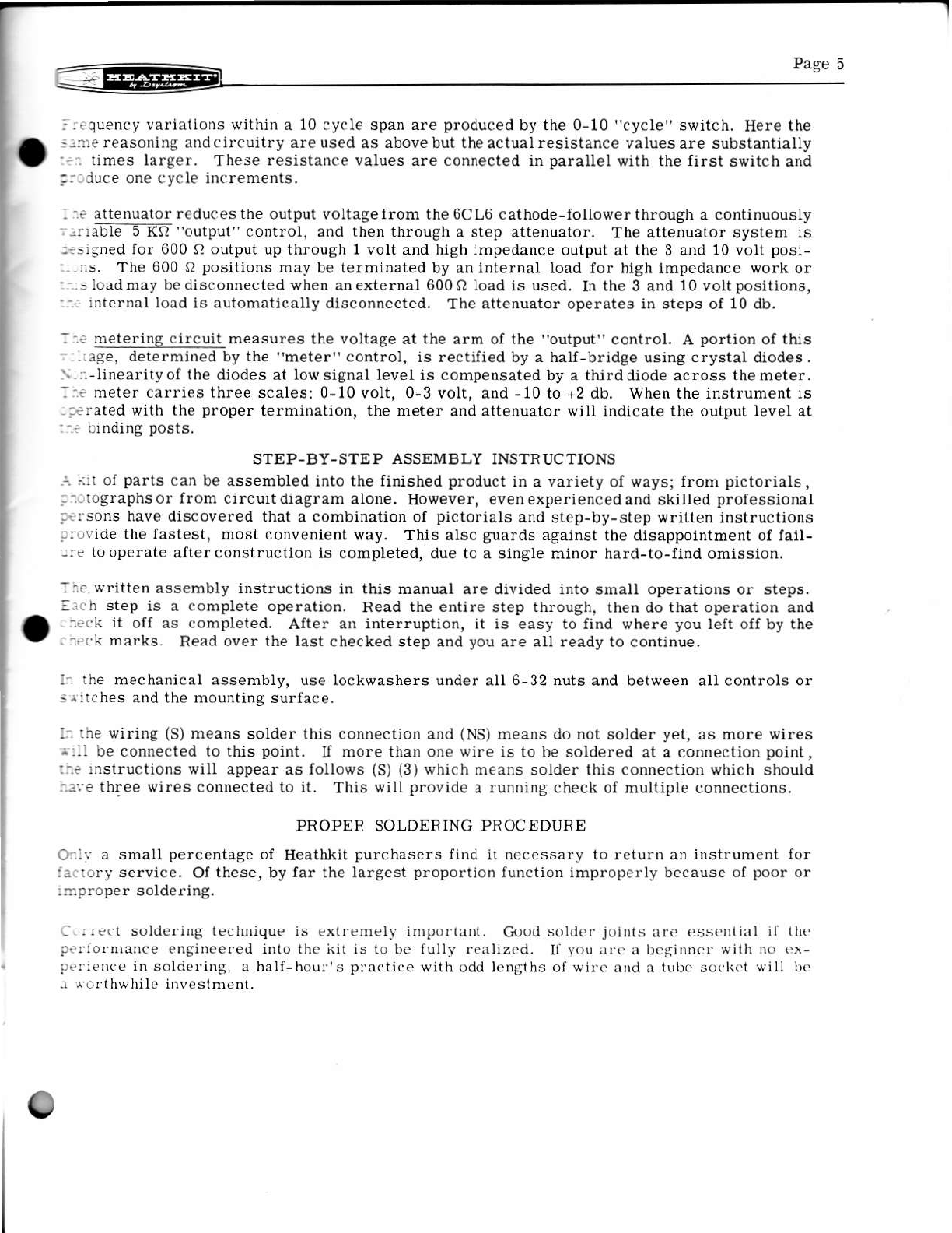
A poor solder j oint will usually be indicated by its appearance.
The solder will stand up in a blob on top oI the connection,
with no evidence of flowingout caused by actual "wetting"of
the contact. A crystalline or grainy texture on the solder
surlace, caused by movement of the joint belore it solidified
is another evidence oI a "cold" connection. In either event,
reheat thejoint until the solder flows smoothly over the en-
tire junction, cooling to a smooth bright appearance. Photo-
graphs in the adjoining picture clearly indicate these two
characteristics.
A good, clean, weII-tinned soldering iron is also important
to obtain c ons i stently perfect connections. For most wiring,
a 25 to 100 watt iron, or the equivalent in a soldering gun,
is very satisfactory. Smaller irons generally wiII not heat the connections enough to flow the
solder smoothly overthe joint and are recommendedonly lor light work, such as on etched cir-
cuit boards, etc. Keep the iron tip clean and bright. A pad of steelwool may be used to wipe
the tip occasionallv during use.
Take this precaution and use reasonable care during the assembly of the kit. This will inaure
the wonderful satisfaction of having the instrument operate perfectly the Iirst time it is turned
^-" o
",frTJ"',lth.
to"mq'
.\g
PICTORIAL 1
OOO
O

P"su8 r-@E4EEEl
CI
I
Pictorial 2
li!#tEEBr ",u"n
Figue 1
H
I
Figure 2
7-PIN
SOCKET sockE T
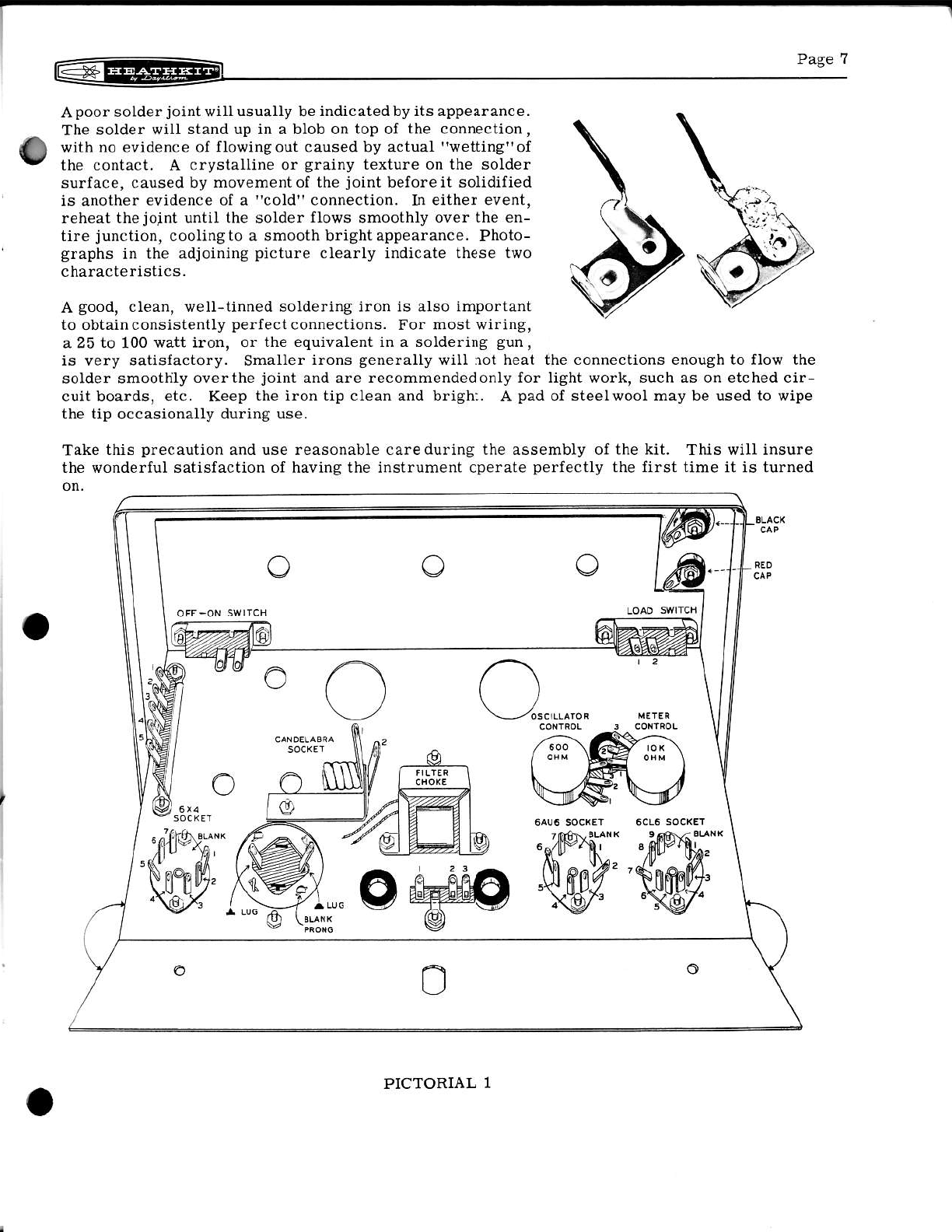
NOTE: The term "6-32 hardware." means that a 6-32 x
!!" screw, #6 lockwasher aJId a 6-32 nut is to be-ilifl
6Iess specitied otherwise-
Refer to Plctorial 1 for the foUowing steps.
(') Mount the two ?-pin and one g-pin weJer t],?e tube
sockete on the chassis v/ith 3-48 screvs and nuts.
See Figlree 1 a.nd 2 for identification. Note the po-
sition of the blank spaces in Pictorial 1 on Pa.ge 6.
Observe that the sockets mount below the chassls,
(?) Mount the Condeuser mounting waJer on top of tIe
chassis. At the same tirDe, install the candelabra
lamp socket as shown in Figure 3.
Figure 3
) Instalt the three 3/8" rubber grommets in posiflons shown ifl pictorial 1.
) Mount the s-lug terminal strip v.ith 6-32 hardware as shown,
) Mount the lilter choke below the chassis with 6-32 hardware.
) Mount the po{rer transformer on top of the chassls. Also install the 3-lug terminat strip
as shov,n ln Figure 4
l, ( j) Molmt the 600 osciilator control with a control lockwasher and a
control nut. See Figure 5.
(,/) Mount the 10 KO meter control in the saEe marurer.
(\
(.
(
+ 6-32
I
@o@
NUT
(A Fasten the panel to the chassis by rnstalling the slide switches. Use 6-32 lErdware, with
' the screw through the panel, the chassis and the switch. Note the position of each switch
in Pictorial 1(lugs inward). Check the alignmentof the three holes in the paneland chassis
before tightening the screws.
{ ' ) Instau the binding posts. Use binding post base, insulator bushings, solder lug and 6-32
nut. See Figure 6. On the one nearest the edge of the panel. inctude a targer control sol-
der Iug between the bushing and rhe lnslde of the panel.
( /) Install the 5 KQ output control on rhe panel with a lockwasher between control and panel and
/ a nickel washer between control nut and panel. See pictorial 2 Ior position.
( )tr Install the multiplier switch in the same manner.
CONTROL !OCATING
TAB
Figure 5Figure 4l
I
.T
I

Paselo @EEiFr
6.,; Figure 8
'-,,"d
Figure 6Figure 7
METER SUB-ASSEMBLY
Figure I
(,7) Install the meter on the front panel with the hardware supplied in the meter bo>r.
( ) nemove one nut and the solder lug lrom each meter stud. NOTE: HoId the inner nut while
Ioosening the outer nut, so no strain is placed on ihe plastic meter housing. Run the re-
maining nut down on the meter stud.
( ) Install the terminal board on the meter studswith the solder lugs and nutsthat came on the
meter.
( ) slip the 3/8" fiberglas sleeving over the pilot larnp e.rd install the lamp in its socket.
Slip t}le sleeving against t]le panel.
( )' Solder the pilot Iight socket to the terminals as sholvn in Figure ? (S).
WIRE THE 5.LUG STRIP
( ) Connect a 2KQ reeistor between lug 1 (NS) and lug 4 (NS). See Figure 8 aird Pictorial 3.
(- ) Connect a l0 KQ resistor between lug 4 (NS) and iug 5 (NS)
(- ) Connect another 10 fO resistor between lug 2 (NS) and lug 5 (NS). Make sure the lead wires
do not touch connections to lug 4.
( - ) Connect a 5 1/2" wirc between lug 4 (NS) and the negative (-) Iug (S) on the meter'
( ) Connect a ? 1/2" wire between lug 2 (NS) and the positive (+) lug (S) on the meter.
( ) Connect a crystal diode with the cathode tead (see page 23 for coding of cathode on diodes)
to lug 1 (S) (2). Connect the other lead to lug 2 (NS). Leave Ieads as long as possible.
( ) Connect a second crystal diodewith the cathode lead to lug 2 (S) (4). Connect the otherlead
to Iug 3 (NS). Leave leads as long a6 possible.
( ) Connect a third crystal diode with the cathode lead to lug 3 (NS). Connect the otherlead to
Iug 4 (S) (a). Leave leads as long as possible.
(r) InstaU the lilter condenser ontop oI thechassis bypassiug the mounting prongsthrough the
slots in the mounting wafer, (make sure the condenseris properly positioned) and twist the
prongs 1/8 turn with a pair of pliers. See Figure I and Pictorial 1 on Page ?.
CHASSIS WMING
15),
(r'|,
()
()
I n"t"" to Pictorial 3 ( Iold-out from Page
(i.) Place the transformer leads through the grommets and connect the red-yettow tead to a
tvristed mounting prong (NS) on the filter condedser.
Connect the red leads to pin 1 (S) and pin 6 (S) on the 6X4 socket.
Connect the green leads to pin 3 (NS) and pin 4 (NS) on the 6X4 socket.
Connect a wire between pin 3 (NS) on the 6X4 socket and the twisted mounting prong (S) (2)
on the filter condenser.
(-.) Twist two 6 l/2" Iengths of wire together and connect one end to pin 3 (S) (3) and pin 4 (S)
(2) on the 6X4 socket. Connect the other end to pin 3 (NS) and pin 4 (NS) on the 6AU6 6ocket.
(- ) Twist twd 2 1/2,, lengths of wire together and connect one end to piD 3 (NS) and pin 4 (NS)
on the 6AU6 socket. Connect the other end to pin 4 (S) and pin 5 (S) on the 6CL6 socket.
( ) Twist two 11,, Iengths oI wire together and connect one end to pin 3 (S) (g) and pin 4 (S) (A)
on the 6AU6 socket. Place the other end through the nearest grommet and connect to the
pilot light termina-Is (S) on the meter terminal board as shorrn in Pictorial 2 on Page ?.
( .) Connect a wirebetween pin 7(S) on 6X4socketand ^ marked lug(NS)onthe fi lter condenser.
( ) Connect one lead lrom the filter choke to the r marked lug (S) (2) on the lilter condenser.
( ) Connect the other lead oI the filter choke to the . marked tug (NS) on the filter conalenser.
( ) Connect a wire between the - marked tug (S) (2) on the filter condenser and pin 3 (NS) on the
6CLO socket.
( , Twist two 11 1/2" lengths oI wire together and connect one end to the OFF-ON slide switch
(S). Connect the other end to lug 2 (NS) and Iug 3 (NS) on the termiDal strip.
('\) Connect one black transformer lead to lug 3 (S) (2) and the other black lead to fug 1(NS) or
the terminal strip.
(\) Connect a wire between a second twisted mounting prong (S) on the filter condenser and
i through lug 2 (NS), through lug 3 (NS) on the 600 Q oscitlato. control to lW 1 (NS) on the
10 KQ meter control.
(,-) Connect a wire between Iug 1(S) on the candelabra socket and lW 1(NS) on the 600s) oscil-
Iator control.
( ) Connect a 330 O resistor betv,/een lug 1 (S) (2) on the oscillator control, through pin ? (S) to
pin 2 (NS) on the 6AU6 socket.
( ) Connect a wire between pin 5 (S) on the 6AU6 socket and pin I (S) on the 6CL6 socket.
(. ) Connect a 120 I(O resistor between pin 6 (NS) (use sleeving over this lead) on the 6AU6
. socket and through pin B (S) to pin 3 (NS) on the 6CL6 socket.
(/ ) Connect a 47 O resistor between pin 1 (S) and pin ? (NS) on the 6CL6 socket.
o
(.)( ) tcate svitch #63-108 and position lt ag
' ahonm in Figure 11.
(.)( ) Connect a 50KQ precision resistorbetween
Iug I (S) (double clip)on the lront section and
through Iug I (S) to lug 10 (NS) on the rear
aection,
( )( ) Connect a 100 KQ precision resistor between
lug 10 (S) on the front section, lhrough lug
l0 (S) (2) lo lug I (NS) on lhe rear section.
( )( ) Connect a 25KO precision resistorbetween
lug 1 (s) on the front eection, throwh Iug 1
(S) (2) to lue 2 (NS) on the rea. section.
( t)( ) Connecta33.3 KQ plecision resistor between
' lug 2 (S) on the front section, through lug 2
(S) (2) to lug 3 (Ns) on the rear section.
1')( j) connect a 50Ko precision resistolbetween
' lug 4 (S) (double clip) on the rear section,
through lug 4 (S) to lug 5 (NS) on the lront
section,
-!L!r
INIEC
f
Pase 12 |]<@Fl
p( Connect a 47 Ksl 2 vatt resistoi between pin 2 (s) and through ptr 6 (8) to pin 3 (S) on the
6CLO socket.
Connect a 16 gfd 150 volt electrolytic condenser c,ith the positive (+) lead to pin 6 (S) (2) and
the negative (-) lead to pin 2 (S) (2) on the 6AU6 socket. Use sleeving on both lead6. Place
condedser cloae to chassis,
( ) Place the line cord through the hole in the rear edge of the chassis. Connect one lead to
lug 1 (S) (2) and the other lead to lue 2 (S) (2) on the terminal strip.
( ,) IrstaU the line cord etrain reliei in the hole in the rear edge of the chassis as shown in
Pictorial 3.
I
I
( ) Connect a 20!.Id 350volt e lectrolytic condenser with the
negative (-)lead to lug 2 {NS) on the candelabra socket
and the positive Iead (+) topin ?(NS) onthe 6CL6socket.
Use sleeving on these Ieads.
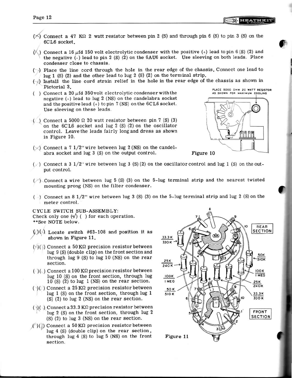
( ) Connect a 5000 O 20 watt resistor between pin ? (S) (3)
on the 6CLG socket and Iug 2 (S) (2) on the oscillator
control. Leavethe leads fairly longand dress as shov,/n
in Figure 10.
( . ) Connect a ? 1/2"wire between lug 2 (NS) on the candel-
abra socket and lug 3 (S) on the output control. Figure l0
( ) Connect ^ 3 1/2" wire between Iug 3 (S) (2) on the oscillator control and lug 1 (S) on the out-
put control.
( -) Connect a wire between lug 5 (S) (3) on the 5-lug terminal atrip and the nearest twisted
mounting p.ong (NS) on the filter condense!.
( ) Connect an 8 1/2" wire between lug 3 (S) (3) on the s-lug terminal strip and lug 2 (S)on the
meter control.
CYCLE SWITCH SUB.ASSEMBLY:
check onlv one 1y') 1 1 for each operation.
**See NOTE below.
]!9lL
l9l! -?!]!
]j.lr
Figure 11

@EEEEEI paeer.
q )t ) Connect a IO0KQ precision resistor between lug 5 (S) on the rear section, through lug 5(S)
(Z) to lug 6 (NS) on the front 6eclion.
(, )(,,/aonnect a 25 Ko precision resistor between Iug 6 (S) on the rear section, through lug 6 (s)
(2) lo lug ? (Ns) on the front seclion.
0i)( ) Connec.t a 33.3 KQ precision resisto, between lug 7 (S) on the real section, through Iug 7
(S) (2) to lug 8 (NS) on the lront section.
**Now repeat each step andcheck the second M for each operation, as the second CYC LE switch
is wired. substitute 5io Ko 5% Ior 50 Ko, 1 megohm 5% for 100 Ko, 240 Ko 5% for 25 Ko and
330 KO 5% lor 33.3 KO.
( ,) Instalt theprecision cycle switch through chassis andpanel with lockwasher, nickel washer
and conlrol nut in the 0-100 position.
( ) Install the 5% cycte svitch in the same manner in the 0-10 position.
Connect a 4? p /rf condenser between lug 1 (S) onthefront
and Iug f (S) on the rear oI the multiplier switch.
Connect a 500 puf condenser between lug 2 (S)onthe lront
alld lug 2 (S) on the rear.
Connect a .005 gId condenser between lug 3 (S) on the
(\)
(_-)
() front and lug 3 (S) on the rear.
( ) Connect a .05 /.rld condenser between lug 4 (S) on the
Iront and lug 4 (S) on the rear.
Connect a .5pld condenser between lug 5 (S) onthe front
and tug 5 (S) on the rear.
Connect a 4 1/2" wire betrreen lug 6 (S) on the lront oI
the multiplier switch and a third twisted mountingprong
(S) (2) on the filter condenser.
Connect a 3 1/2" wire between lug ? (S) on the lront of
the multiplier switch and rug 3 (NS) (double lug) on the
front oI the precision cycle svitch.
1' ) Connect a 3" v,ire between lug 3 (S) (2) (double lug) on
'' the front of the precision cycte switch and Iug 3 (NS)
(double lug) on the front of the 5% cycle switch.
I ) Connect a 4 l/2" wire between lug 3 (S) (2) (double Iug) on
and pin 1 (S) on the 6AU6 socket.
(' l Connect a 3" wire between lug 8 (s) (2) on the front of the precision cycle switch and Iug 8
(NS) on the Iront oI the 5% cycle switch.
( ) Connect a 2" wire between lug I (S) (3) on the Iront oI the 5% cycle switch and lugS (NS) on
the rear oi the preciaion cycle switch.
-1. ) Connect a 3" wire between lug 3 (NS) on the rear of the precision cycle switch and lug 3 (S)
(2) on the rear of the 5% cycle switch,
O,r
()
()
Figure 12
the Iront o{ the 590 cycle switch
I
t
,.s"14 li:ffiEEF|
( ) Connect a 4 1/2" wire between lug 3 (S) (4) on the rea! oi u1e precision cycle switch and Iug
6 (S) on the rear o{ the hultiplier switch.
( ) Connect a 3" wire between lug 8 (S) (double lug) on the rear oi the precision cycle switch
and lug 8 (NS) (double lug) on the rear of the 5% cycle switch.
(., ) Connect a I I /2 " wire between lug B (NS) (double lug) on the rear oI the 5% cycle switc h and
' lug 2 (S) (3) on the candelabra socket.
( ) Connect a 4" wire between lug 8 (S) (3) (doubte lug) on the rear oI the 5% cycle switch and
lug ? (S) on the rear oI the multiplier switch.
Dress all preceding wires so they will not interfere q-rth op€ration of the s*itches-
ATTENUATOR SWITCH SUB.ASSEMBLY
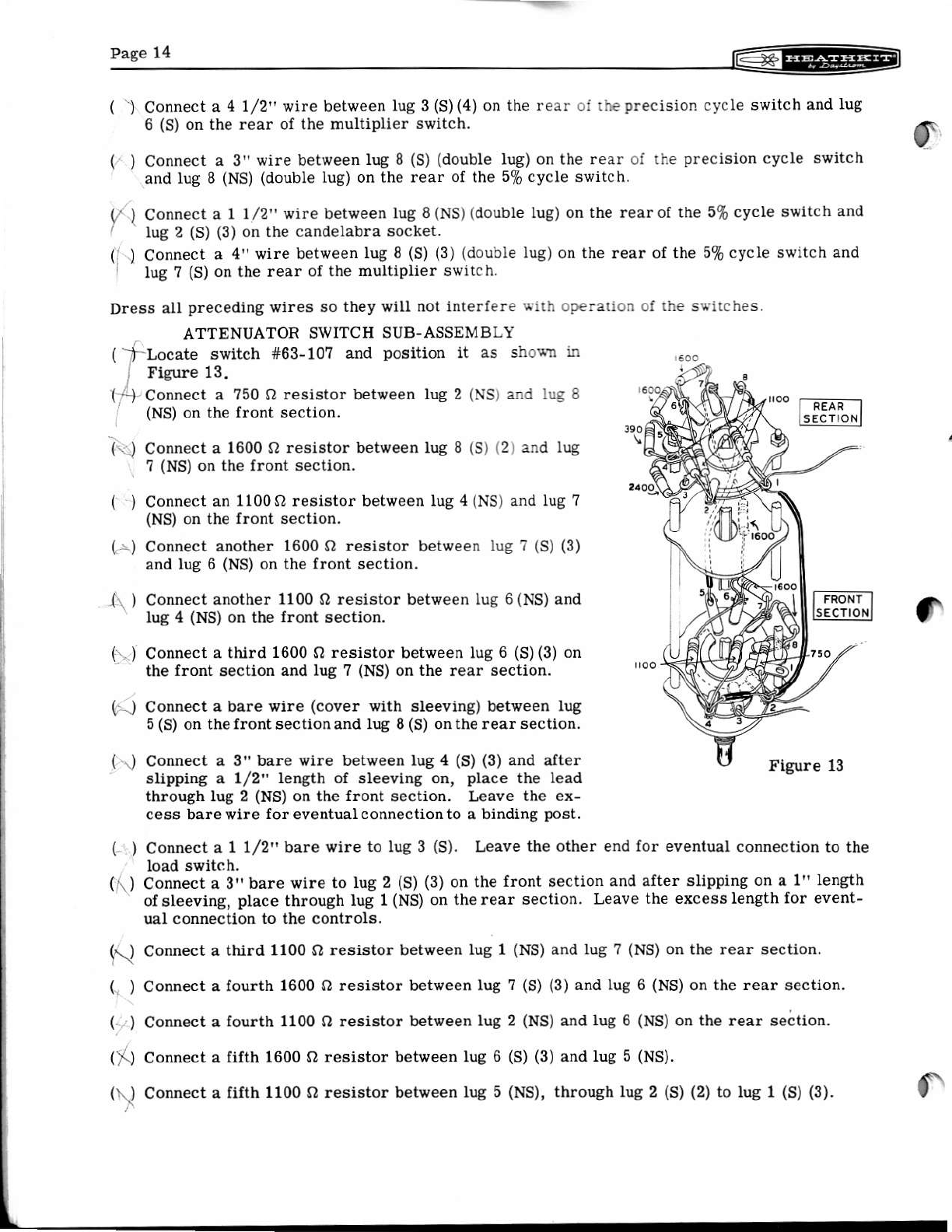
( -frl-ocate Ewitch #63-10? and position it as shocn " uo"
, Figure 13.
( -) Connect a 750 O resistor between lug 2 (NS) and IUE 8
(NS) on the front section.
(.)
()
()
()
( ) Connect another 1600 Q resistor bet,reen lug ? (S) (3)
and lug 6 (NS) on the front section.
()
Connect a 1600 O resistor behoeen lug 8 (S) (2) and lug
? (NS) on the front sectior.
Connect an 11000 resistor between Iug 4 (NS) and lug ?
(NS) on the front section.
()
( ) Connect a I 1/2" bare wire to lug 3 (S). Leave the other end for eventual connection to the
load s{itch.
( r.) Connect a 3" bare r,ire to lug 2 (S) (3) on the iront section and after slipping on a 1" length
ofsleeving, place through lug 1(NS) on the rear Bection. Leave the excesslength for event_
Connect another 1100 O resistor between lug 6 (Ns) and
lug 4 (NS) on the front section.
Connect a third 1600 O resistor between lug 6 (S) (3) on
the front section and Iug ? (NS) on the rear section.
Connect a bare v,/ire (cover with sleeving) between lug
5 (S) on the (rontsectionand lug 8 (S) onthe rear section.
Connect a 3" bare wire between lug 4 (S) (3) and after
slipping a 1/2" length of sleevlng on, place the Iead
thlough lug 2 (NS) on the front section. Leave the ex-
cess barevlre lor eventual c onnection to a binding post.
ual connection to the controls.
Connect a third 1100 Q resistor between lug 1 (NS) and tug ? (NS) on the rear section.
Corhect a lourth 1600 O resistor between lug 7 (S) (3) and Iug 6 (NS) on the rear section.
Connect a fourth 11OO O resistor behveen lug 2 (NS) and lug 6 (NS) on the rear se;tion.
Connect a fifth 1600 Q resisto! between lug 6 (s) (3) and lug 5 (NS).
Connect a Iifth 1100 o resistor between lug 5 (NS), throwh lug 2 (s) (2) to lug 1 (S) (3).
6.1
()
()
($
('.1
f

------
* +- H:g;tlirg
1 ) Connect a 390 O resistor between Iug 5 (S) (3) and lug 4 (NS).
| ( .{ co.'nect a z40o Q resistor between lug 4 (s) (2) and lug 3 (Ns).
(\) Again referring to Pictorial 3, connect a 560 o lesistor between lug 2 (s) on the load
switch, through the nearest bindhg post solder lug (S). Leave the excess lead wire for
eventual ,connection to the attenuator switch.
( ) InstaU the attenuator switchwith lockwasher, nickel was her and c ontrol nut throughthe chas-
sis and panel. Position as shown.
x.]
i') Conneci the bare wire from Iug 1 on the rear section of ihe attenuator switch to lug 1 (S) (2)
on the meter.onirol.
Connect a 4700O resistor between lug 3 (S) on the meter control and lug 3 (NS) on the rear
( 'i)
(l )
()
()
This completes the wiring oI the instrument. Shake out all the ioose solder bits and wire clip-
prngs. Inspect the qiring carefully. Check lead dress (bare leads contacting metal parts, com-
!onenis touching moving parts) and inspect each connection carefully {or proper soldering.
' section oI the attenuator switch.
Connect a 5" wire between lug 2 (S) on the output control and Iug 3 (S) (3) on the rear sec-
tion of the attenuator switch.
Conn€ct the bare wire from lug 3 on the front section of the attenuator switch to lug I (S)
on the Ioad switch.
Connect the bare wire from Iug 2 on the lront section of the attenuator switch to both the
Iarge and small solder lugs (S) on the binding post in the corner of the panel.
Connect the bare wire Ieft on the other binding post to Iug 1 (S) on the lront section of the
attenuator switch.
@
6AU6
s
@
a
Figure 14
( ) Refer to Figure 15 aDd attach the knob pointers on the five knobs.
SETSCREW SMALL
KNOB
f( ) furn all the controla and awitches to their fuIl counterclockwise position.
Figure 15
6X4
o
@
o
(D
ta
Pictorial 3

Paee 16 |z<@=El
(\ ) Arstaff the five lorot s on the shaJts of the panel controls vrith the pointers at the extreme
counterclockwise marking on the panel, and tighten the setscrews.
( ) InstaU the 3 watt 115 volt candelabra lamp and the 6X4, 6AU6, and
6CL6 tubes in their proper sockets. See tr'igure 14,
( ) Instau the handle on the cabinet with 10-24 screws.
( ) Molmt tfle lour rubber feet with 6-32 x 1/2" screws, #8 flat
washers, #6 lockwashers, and 6-32 nuts as shown in Figure 16.
Figure 16
INITIAL TEST AND ADJUSTMENT
Plug the Iine cord into a 105-125 volt 50-60 cycle outlet. Do not plug into an ouuet of higher
voltage or Iowerfrequency, o, a DC outtet, as an incorrect power source will damagethe trans-
Turn powerswitch on andobserve tubes and pilot tampas they light up. IJ they donot Iight, turn
power off and investigate Iilament circuit \?iring. Set OSCILLATOR and METER controls about
midway. Set precision (0-100) CYCLEswitchtol0 ormore and advance OUTPUT control. This
should show a reading on the meter.
Calibrate the meter. NOTE: IJ in the loLlowing test the OUTPUT control is teft oIf or fuUy
counterclockwise, it will be severly damaged. Prcceed as Io[ows: Turn both CYCLE switches
to 0. Turn the OUTPUT control to maximum clockwise. Turn the ATTENUATOR to maximum
clockwise (10 volt or +20 db). Connect a wire between the red output binding postand one of the
pilot light terminals on the meter terminai board. Use the terminal that gives a meter indica-
tion. Turn the METEF control to produce a meter reading of 6.3 volts on the O-10 scaLe (a Iit-
tle over halJ-way up the scale). Now remove the wire.
II an accurate AC voltmeter of adequate sensitivity (at least 500 O per volt on the 10 volt range
for instance) is available, it should be used in preference to the above ptocedure. In that case:
select a suitable frequency (between 50 and 3000 cycles, depending on the AC meter used) with
the CYCLE and MULTIPLIER switches and connect the meter to the output oI the generator.
Adiust the METER control to produce equal readings on the two meter6.
Adjust the OSCILLATOR control as follow6: No connections to the output terminats. OUTPUT
control at maximum. CYCLE switches and MULTIPLIER to 10 cycles or more. Turn OSCIL-
LATOR control to give just over lull scale reading on the meter. Select various frequencies
between 10 cycles and 100 kc and iI the output drops below fuII scale, readjust OSCILLATOR
control for full acale. Do not adjust OSCILLATOR controt higherthan necessary as higher than
nominaL distortion wiII result.
This completes the adiustment oI the instrument. Install the generator in the cabinet anal lasten
wlth the two #6 sheet metal screws throwh the rear of the cabinet into the chassis. ro
t6@l Pase 17
IN CASE OF DIFFICULTY
II upon completion of carelul construction, the instrument lails to operate as specified, proceed
as follov/s:
l. Check the wiring carefully step-by-atep. Olten having a lriend check lor you will locate an
error consistently oyerlooked.
2. Inspect yisually lor maljunctioning, such as tubes lighting, discoloring oI resistors through
overheating, etc.
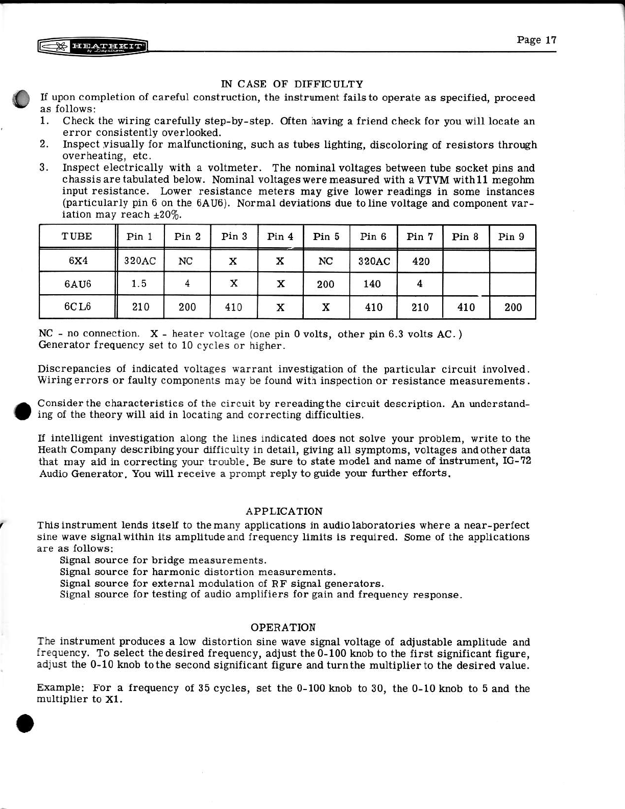
3. Inspect electrically with a voltmeter. The nominal voltagee between tube socket pins and
c has si B are tabulated below. Nominal voltages were measured with a yTVM with 11 megohm
input resistance. Lower resistance meters may give lower readings in some instances
(particularly pin 6 on the 6AU6). Normal deviations due to line voltage and component var-
iation may reach +20%.
TUBE Pin IPin 2Pin 3Pin 4Pin 5Pin 6Pin 7Pin 8Pin I
6X4 3 2OAC NC x x NC 32oAC 420
6AU6 1.5 4xx200 140 4
6CL6 210 200 410 xx410 2to 410 200
NC - no connection. X - heater voltage (one pin 0 volts, other pin 6.3 volts AC. )
Generator Irequency set to 10 cycles or higher.
Discrepancies of indicated voltages warrant investigation oI the particular circuit involved.
Wiringerrors or faulty components may be found with inspection or resistance measurements.
Considerthe characteristics oI the clrcuit by rereadingthe circuit description. An understand-
ing of the theory will aid in locating and correctiDg difficulties.
II intelligent investigation along the iines indicated does not solve your problem, write to the
Heath Company deacribingyour dilliculty in detail, giving all symptoma, voltages andother data
that may aid in correcting your trouble. Be sure to state model and name of inEtrument, 1G-72
Audio Generator. You will receive a prompt reply to guide your further eJforts,
APPLICATION
This instrument lends itself to the many applications in audio laboratories where a near-perfect
sine wave signalwithin its amplitude and frequency limits is required. Some of the applications
are as follows:
Signal source ior bridge mea6ureErents.
Signal source for harmonic distortion measurements.
Signal source for external modulation of RF signal generators.
Signal source lor testing oI audio ampliliers Ior gain and lrequency response.
OPERATION
The instrument produces a lo\r, distortion sine wave signal voltage of adiustable amplitude and
frequency. To select thedesired frequency, adjust the0-100 knob to the first significant figure,
adjust the 0-10 knob tothe second significant Iigure and turnthe multiplierto the desired value.
Example: For a frequency oI 35 cycles, set the 0-100 knob to 30, the 0-10 knob to 5 and the
multiplier to X1.
Table of contents


