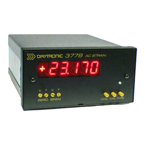
M
ODEL
3778
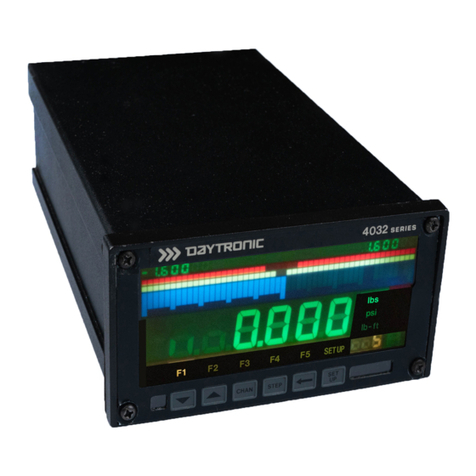
AC STRAIN GAGE PANEL METER
4.CALIBRATION – 2 Point - Dead Weight with known input
This section contains the instructions for calibrating the 3778. Reference the description of the instrument
front-panel (see Page 1). To perform calibration, proceed as follows.
(a) Connect Power, Sensor and Analog terminals as required. Apply power. The front-
panel digital display should light indicating the application of the AC input power. Allow
10 minutes of warm up for stabilization of transducer characteristics. Remove the front
panel cover of the 3778 unit which is held in place by the two small Phillips screws.
(b) Position the front panel switches to the desired settings for the application. Refer to Section 3
for details. Insure TARE is not engaged.
(c) Center the Zero and Span potentiometers as needed by rotating the potentiometers fully CW
(Coarse is 22 turns, Fine is 25 turns), then reverse direction - CCW (Coarse 11 turns and Fine 13
turns) to obtain mid-authority of the controls. Typically this is done on initial calibration. When
recalibrating for minor adjustments this may not be required.
(d) With mechanical Zero or Balance established at the transducer (transducer “relaxed”); Adjust
Wide Zero then Coarse Zero and then Fine Zero for the Zero position reading on the display or
the desired analog output signal. Note: Display can be adjusted independently to the analog
signal when the Coarse Display control is not in the “OFF” position.
(e) Apply a known span reference standard (dead weight torque / load) so the sensor is greater than
50% of the positive full scale (or preferred - the “nominal” operating value of the transducer).
Adjust the Wide Span then Coarse Span and then the Fine Span to obtain an approximate display
or analog value for the instrument. Once this level is establish, Adjust the 3778 Phase control to
obtain the highest magnitude on the display. This “peak” or “hump” will synchronize the
Excitation phase with the return Signal Phase for proper operation of the 3778 unit. Once Phase
has been accomplished, the 3778 will not need to be re-phased for subsequent calibrations unless
the cable or the transducer is replaced. Re-establishment of Wide Span may be needed if the
phase adjustment causes display saturation.
(f) Return the sensor to the Zero position in step (d) and re-adjust the Zero controls as needed to
obtain the proper reading (or analog signal) for the application’s zero position.
(g) Apply a known full scale Load to the sensor. Preferably in the positive direction. This should
represent the “nominal” working level of the sensor. Re-Adjust the Coarse Span and Fine Span
controls, as needed, for precise engineering units reading on the display as well as the analog
output desired.
(h) Repeat Steps (f) and (g) to obtain proper measurement readings since the Gain – Span
controls will affect the Zero amplification of the input signal.
(i) Once completed, if the sensor is going to be utilized in the Negative or CCW mode, it is
recommended to reverse the dead weight Load on the sensor to a known “negative” load and
adjust the Symmetry control for a proper symmetrical reading of the sensor input. Note the
Symmetry control affects the Negative Span for approx. ± 2% of full scale adjustment control.
(j) Re-install the front panel. Fine Span and Zero controls are accessible with front panel installed.
(k) Use the + CAL and – CAL buttons to activate positive or negative shunt for future reference
purposes as a means of verification of the calibration. Sensor should be in the zero or relaxed
position when performing Shunt calibration activation.
Page 16


