DBI SALA Exofit User manual
This manual is intended to meet
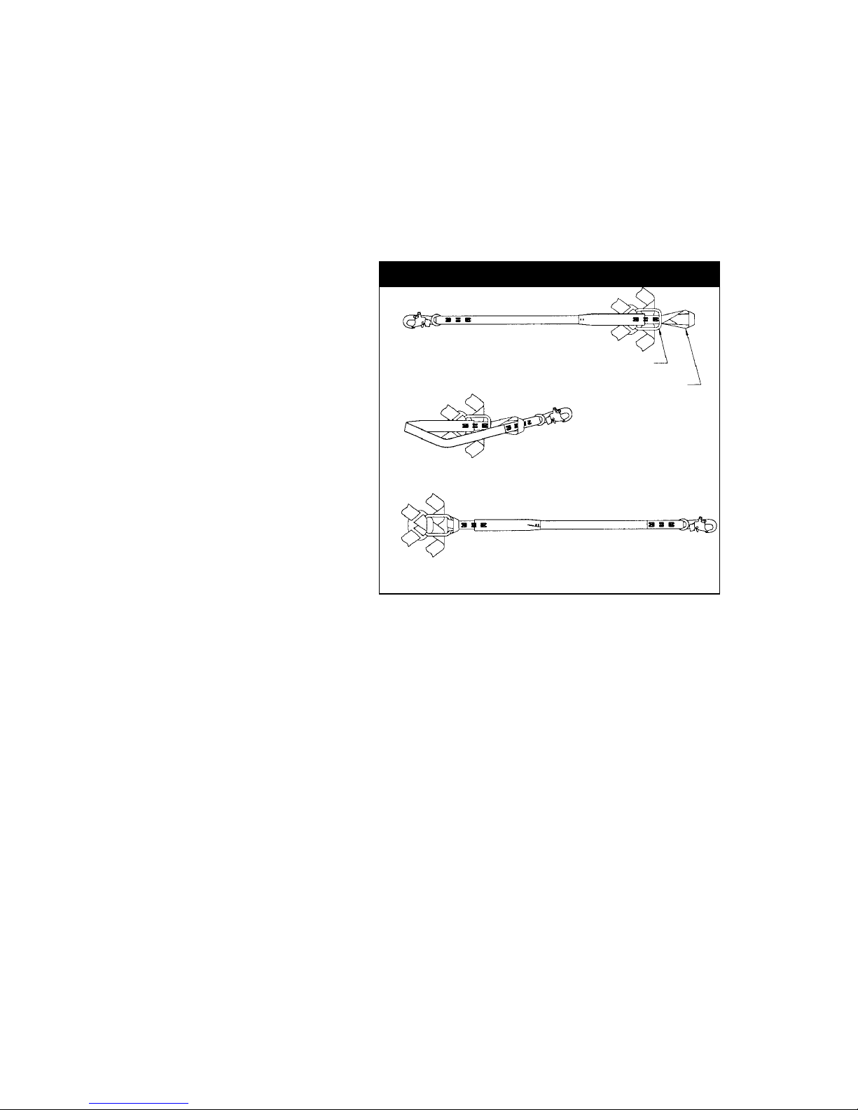
the Manufacturer’s Instructions as
required by ANSI Z359 and should
be used as part of an employee
training program as required by
OSHA.
© Copyright 2008, DB Industries, Inc.
Instructions for the
following series products:
ExoFit Full Body Harnesses
(See back pages for specic
model numbers.)


3
WARNING: This product is part of a personal restraint, work
positioning, suspension, or rescue system. These instructions must be
provided to the user and rescuer (see section 8.0 Terminology). The user
must read and understand these instructions or have them explained to
them before using this equipment. The user must read and follow the
manufacturer’s instructions for each component or part of the complete
system. Manufacturer’s instructions must be followed for proper use and
maintenance of this product. Alterations or misuse of this product or
failure to follow instructions may result in serious injury or death.
IMPORTANT: If you have questions on the use, care, or suitability of
this equipment for your application, contact DBI‑SALA.
IMPORTANT: Before using this equipment, record the product
identication information from the ID label into the inspection and
maintenance log in section 10.0 of this manual.
DESCRIPTIONS
ExoFit Vest Style Full Body Harness: See Figure 1.
ExoFit Cross-Over Style Full Body Harness: See Figure 2.
OPTIONS:
DBI-SALA ExoFit and ExoFit XP Full Body Harnesses are available
with options and accessories. Following is a partial list of
commonly used options and accessories (some options may not
be available on all harnesses):
• Side D-rings
• Front D-rings
• Hip pad with side D-rings
• Tongue buckle body belt
• Lanyard attached directly to D-ring or attachment element

4
Figure 1 - ExoFit Vest Style Full Body Harness
Chest Strap
Shoulder
Strap
Parachute
Buckle
Quick Connect Buckle
Leg Strap
Quick Connect Buckle
Product Warning and
Identification Labels
Dorsal
D-ring
5
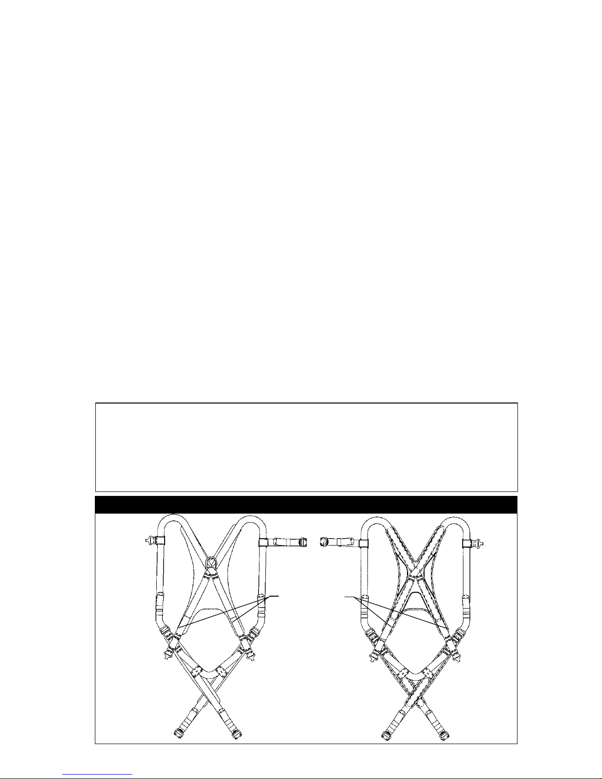
Figure 2 - ExoFit Cross-Over Style Full Body Harness
Leg Strap
Quick Connect Buckle
Parachute
Buckle
Shoulder
Strap
Front Attachment Element
(D-ring Or Web Loop)
Side
D-rings
Dorsal
D-ring
Product Warning and
Identification Labels

6
1.0 APPLICATIONS
1.1 PURPOSE: DBI-SALA ExoFit and ExoFit XP full body harnesses are
to be used as components in personal fall arrest, restraint, work
positioning, climbing, or rescue systems. See Figures 1 and 2 for
harness styles.
Harnesses included in this manual are full body harnesses and
meet ANSI Z359.1 and OSHA requirements. See Figure 3 for
application illustrations.
WARNING: Working at height has inherent risks. Some risks are
noted here but are not limited to the following: falling, suspension/
prolonged suspension, striking objects, and unconsciousness. In the
event of a fall arrest and/or subsequent rescue (emergency) situation,
some personal medical conditions may affect your safety. Medical
conditions identied as risky for this type of activity include but are not
limited to the following: heart disease, high blood pressure, vertigo,
epilepsy, drug or alcohol dependence, psychiatric illness, impaired
limb function and balance issues. We recommend that your employer/
physician determine if you are t to handle normal and emergency use
of this equipment.
A. PERSONAL FALL ARREST: The full body
harness is used as a component of a personal
fall arrest system. Personal fall arrest systems
typically include a full body harness and a
connecting subsystem (energy absorbing
lanyard). Maximum arresting force must not
exceed 1,800 lbs (8 kN).For fall protection
applications connect the fall arrest subsystem
(example: lanyard, SRL, energy absorber, etc.)
to the D-ring or attachment element on your back, between
your shoulder blades.
B. WORK POSITIONING: The full body harness
is used as a component of a work positioning
system to support the user at a work position.
Work positioning systems typically include a full
body harness, positioning lanyard, and a back-up
personal fall arrest system. For work positioning
applications, connect the work positioning
subsystem (example: lanyard, Y-lanyard, etc.) to
the lower (hip level) side or belt mounted work
positioning attachment anchorage elements (D-rings). Never
use these connection points for fall arrest.
C. LADDER CLIMBING: The full body harness
is used as a component of a climbing system
to prevent the user from falling when climbing
a ladder or other climbing structure. Climbing
systems typically include a full body harness,

7
vertical cable or rail attached to the structure, and climbing
sleeve.For ladder climbing applications, harnesses equipped
with a frontal D-ring in the sternal location may be used
for fall arrest on xed ladder climbing systems. These are
dened in ANSI A14.3.
D. RESCUE: The full body harness is used as a
component of a rescue system. Rescue systems
are configured depending on the type of rescue.
For limited access (conned space) applications,
harnesses equipped with D-rings on the shoulders
may be used for entry and egress into conned
spaces where worker prole is an issue.
E. CONTROLLED DESCENT: For controlled descent
applications, harnesses equipped with a single
sternal level D-ring, one or two frontal mounted
D-rings, or a pair of connectors originating below
the waist (such as a seat sling) may be used for
connection to a descender or evacuation system.
E. RESTRAINT: The full body harness is used as a
component of a restraint system to prevent the
user from reaching a fall hazard. Restraint systems typically
include a full body harness and a lanyard or restraint line.
1.2 LIMITATIONS: Consider the following application limitations
before using this equipment:
Figure 3 - Applications
Anchorage
Anchorage
Anchorage Connector
Restraint Lanyard
Anchorage Connector
Connecting Subsystem
(Self Retracting
Lifeline Shown)
Full Body Harness Full Body Harness
Fall Arrest Restraint
Work Positioning
Anchorage
Anchorage
Connector
Back-up
Fall Arrest
System
Full Body
Harness
Restraint Lanyard
Anchorage
Anchorage
Connector
Ladder
Cable Sleeve
Cable
Cross-over
Full Body
Harness
Ladder Climbing

8
A. CAPACITY: These full body harnesses are designed for
use by persons with a combined weight (clothing, tools,
etc.) of no more than 420 lbs. (191 kg) Make sure all of
the components in your system are rated to a capacity
appropriate to your application.
B. FREE FALL: Personal fall arrest systems used with this
equipment must be rigged to limit the free fall to 6 feet
(ANSI Z359.1). Restraint systems must be rigged so that
no vertical free fall is possible. Work positioning systems
must be rigged so that free fall is limited to 2 feet (.6 m)
or less. Personnel riding systems must be rigged so that
no vertical free fall is possible. Climbing systems must be
rigged so that free fall is limited to 18 inches (.5 m) or less.
Rescue systems must be rigged so that no vertical free fall
is possible. See subsystem manufacturer’s instructions for
more information.
C. FALL CLEARANCE: See Figure 4. There must be sufficient
clearance below the user to arrest a fall before the user
strikes the ground or other obstruction. The clearance
required is dependent on the following factors:
• Elevation of anchorage • Connecting subsystem length
• Deceleration distance • Free fall distance
• Worker height • Movement of harness
attachment element
See subsystem manufacturer’s instructions for more information.
Figure 4 - Fall Clearance
Connecting Subsystem
(Energy Absorbing Lanyard shown)
Working Level
Free Fall
6 ft. max (ANSI Z359.1)
Deceleration
Distance
Total Fall Distance
(Free Fall + Deceleration)
Lower Level or Obstruction
9
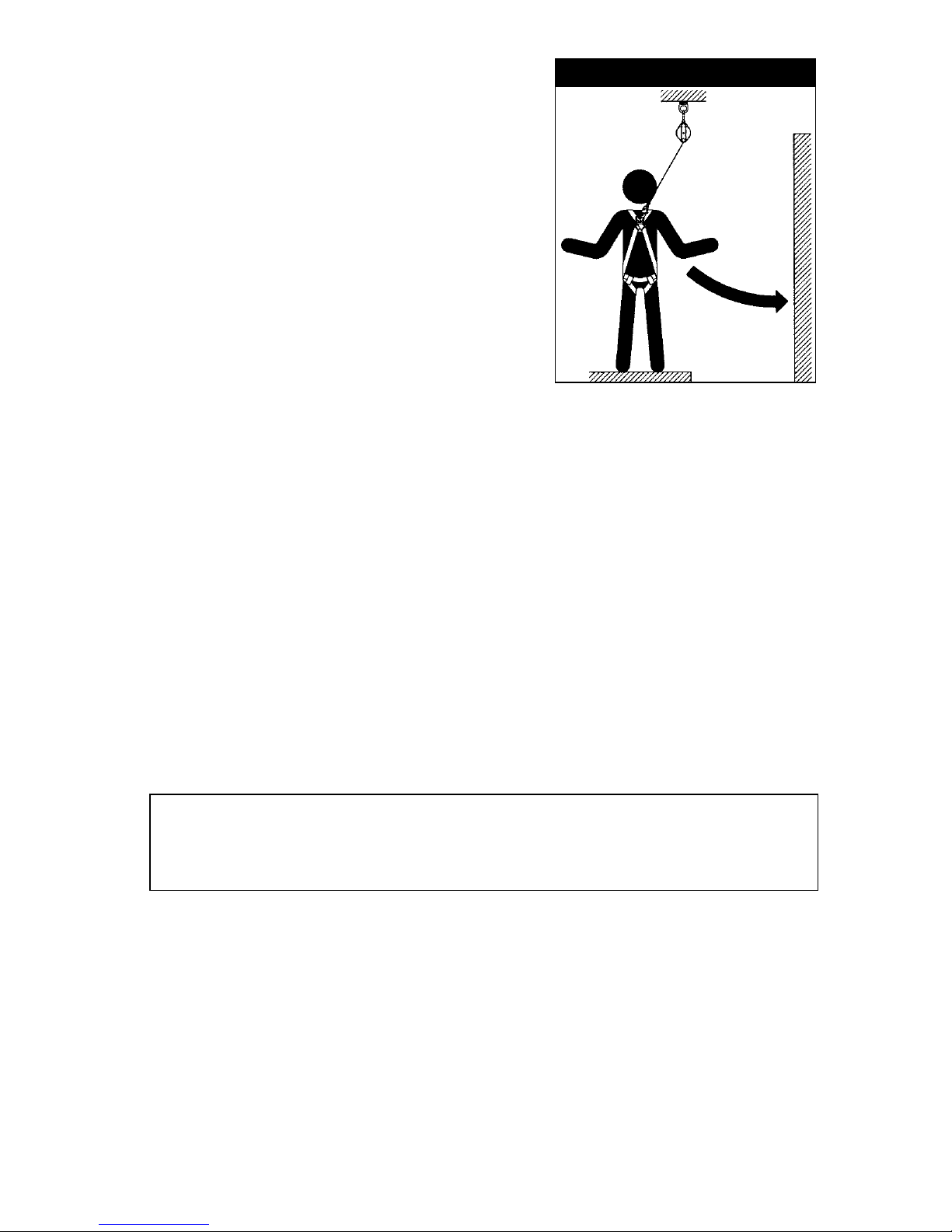
D. SWING FALLS: See Figure 5.
Swing falls occur when the
anchorage point is not directly
above the point where a fall
occurs. The force of striking
an object in a swing fall may
cause serious injury or death.
Minimize swing falls by working
as close to the anchorage point
as possible. Do not permit a
swing fall if injury could occur.
Swing falls will significantly
increase the clearance required
when a self retracting lifeline or
other variable length connecting
subsystem is used.
E. EXTENDED SUSPENSION: A full body harness is not
intended for use in extended suspension applications. If the
user is going to be suspended for an extended length of
time it is recommended that some form of seat support be
used. DBI-SALA recommends a seat board, suspension work
seat, seat sling, or a boatswain chair. Contact DBI-SALA for
more information on these items.
F. ENVIRONMENTAL HAZARDS: Use of this equipment in
areas with environmental hazards may require additional
precautions to prevent injury to the user or damage to the
equipment. Hazards may include, but are not limited to;
heat, chemicals, corrosive environments, high voltage power
lines, gases, moving machinery, and sharp edges.
G.
TRAINING: This equipment must be installed and used by
persons trained in its correct application and use. See section 4.0.
IMPORTANT: When working with tools, materials, or in high
temperature environments, ensure that associated fall protection
equipment can withstand high temperatures, or provide
protection for those items.
1.3
Refer to national Standards including ANSI Z359 (.0, .1, .2, .3, and
.4) family of standards on fall protection, ANSI A10.32, and applicable
local, state and federal (OSHA) requirements governing occupational
safety for more information about work positioning systems.
2.0 SYSTEM REQUIREMENTS
2.1 COMPATIBILITY OF COMPONENTS: DBI-SALA equipment
is designed for use with DBI-SALA approved components and
subsystems only. Substitutions or replacements made with non-
approved components or subsystems may jeopardize compatibility
of equipment and may effect the safety and reliability of the
complete system.
Figure 5 - Swing Fall
Swing
Fall
Hazard
10
2.2 COMPATIBILITY OF CONNECTORS: Connectors are considered
to be compatible with connecting elements when they have been
designed to work together in such a way that their sizes and
shapes do not cause their gate mechanisms to inadvertently open
regardless of how they become oriented. Contact DBI-SALA if you
have any questions about compatibility.
Connectors (hooks, carabiners, and D-rings) must be capable
of supporting at least 5,000 lbs. (22.2kN). Connectors must be
compatible with the anchorage or other system components. Do not
use equipment that is not compatible. Non-compatible connectors
may unintentionally disengage. See Figure 6. Connectors must be
compatible in size, shape, and strength. Self locking snap hooks
and carabiners are required by ANSI Z359.1 and OSHA.
2.3 MAKING CONNECTIONS: Only self-locking snap hooks and/or
carabiners shall be used with this equipment. Ensure all connectors
are fully closed and locked and compatible.
DBI-SALA connectors (snap hooks and carabiners) are designed to
be used only as specied in each product’s user instructions. See
Figure 3 for inappropriate connections. DBI-SALA snap hooks and
carabiners should not be connected:
A. To a D-ring which another connector is already attached.
B. In a manner that would result in a load on the gate.
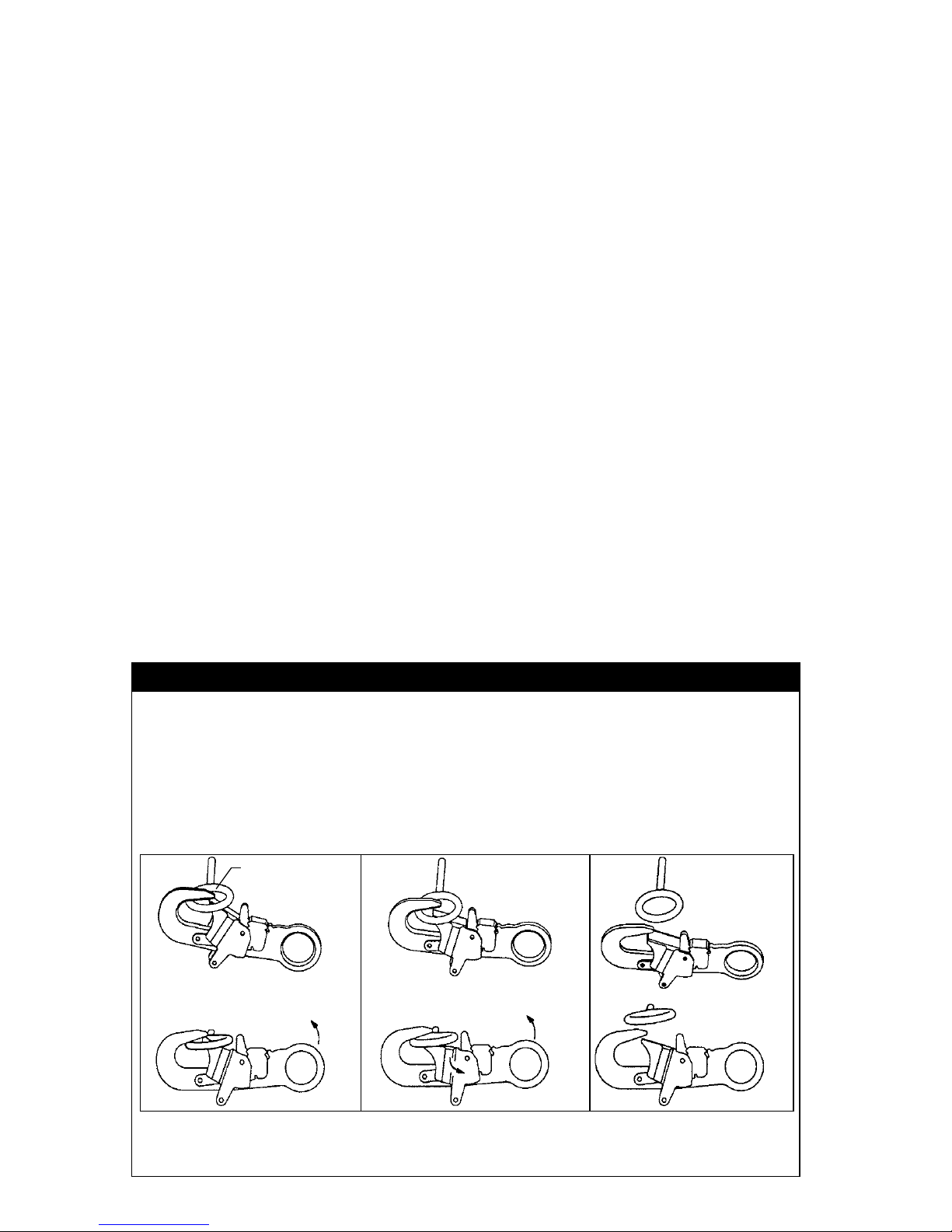
If the connecting element that a snap hook (shown) or carabiner attaches to is
undersized or irregular in shape, a situation could occur where the connecting
element applies a force to the gate of the snap hook or carabiner. This force
may cause the gate (of either a self-locking or a non-locking snap hook) to
open, allowing the snap hook or carabiner to disengage from the connecting
point. For ANSI Z359.1-2007 compliant hooks, there are no restrictions on the
size or shape of the mating connector provided the snap hook is free to align
with the applied load as intended.
1. Force is applied to
the snap hook.
2. The gate presses against
the connecting ring.
3. The gate opens
allowing the snap hook
to slip off.
Figure 6 - Unintentional Disengagement (Roll-out)
Small ring or other
non-compatibility
connector

11
NOTE: Large throat snap hooks should not be connected to standard
size D‑rings or similar objects which will result in a load on the gate
if the hook or D‑ring twists or rotates, unless the snap hook complies
with ANSI Z359.1‑2007 and is equipped with a 3,600 lb gate. Check
the marking on your snap hook to verify that it is appropriate for your
application.
C. In a false engagement, where features that protrude from
the snap hook or carabiner catch on the D-ring, and without
visual confirmation seems to be fully engaged to the anchor
point.
D. To each other.
E. Directly to webbing or rope lanyard for tie-back (unless
specifically provided by the manufacturer).
F. To any object which is shaped or dimensioned such that the
snap hook or carabiner will not close and lock, or where roll-
out could occur.
OTHER RESTRICTIONS:
• Do not make connections where the hook locking mechanism
can come into contact with a structural member or other
equipment and potentially release the hook.
•
Do not connect a snap hook into a loop or thimble of a wire rope
or attach in any way to a slack wire rope.
• The snap hook must be free to align with the applied load
as intended (regardless of the size or shape of the mating
connector).
• A caribiner may be used to connect to a single or pair of soft
loops on a body support such as a body belt or full body harness,
provided the carabiner can fully close and lock. This type of
connection is not allowed for snap hooks.
Figure 7 - Inappropriate Connections
12
• A carabiner may be connected to a loop or ring connector that
is already occupied by a choker style connector. This type of
connection is not allowed for snap hooks.
2.4 CONNECTING SUBSYSTEMS: Connecting subsystems (self-
retracting lifeline, lanyard, rope grab and lifeline, cable sleeve)
must be suitable for your application. See section 1.1. See
subsystem manufacturer’s instructions for more information. Some
harness models have web loop connection points. Do not use
snap hooks to connect to web loops. Use a self-locking carabiner
to connect to a web loop. Ensure the carabiner cannot cross-
gate load (load against
the gate rather than
along the backbone
of the carabiner).
Some lanyards are
designed to choke onto
a web loop to provide a
compatible connection.
See Figure 8. Lanyards
may be sewn directly to
the web loop forming a
permanent connection.
Do not make multiple
connections onto one
web loop, unless choking
two lanyards onto a
properly sized web loop.
2.5 ANCHORAGE STRENGTH: The anchorage strength required
is dependent on the application type. The following are the
requirements of ANSI 359.1 for these application types:
A. FALL ARREST: Anchorages selected for fall arrest systems
shall have a strength capable of sustaining static loads
applied in the directions permitted by the system of at least:
1. 5,000 lbs. (22.2 kN) for non-certified anchorages, or
2. Two times the maximum arresting force for certified
anchorages. When more than one fall arrest system is
attached to an anchorage, the strengths set forth in (1)
and (2) above shall be multiplied by the number of systems
attached to the anchorage.
B. RESTRAINT: Anchorages selected for restraint and travel
restraint systems shall have a strength capable of sustaining
static loads applied in the directions permitted by the system
of at least:
1. 1,000 lbs. (4.5 kN) for non-certied anchorages, or
2. Two times the foreseeable force for certied anchorages.
When more than one restraint and travel restraint system
is attached to an anchorage, the strengths set forth in (1)
and (2) above shall be multiplied by the number of systems
attached to the anchorage.
Figure 8 - Web Loop Connection
Insert lanyard web loop
through web loop or
D-ring on harness
Harness Web
Loop or D-ring
Web Loop on
Energy Absorbing Lanyard
Insert opposite end of lanyard through the
lanyard web loop
Pull the lanyard through the connecting web loop
to secure
13
C. WORKING POSITIONING: Anchorages selected for work
positioning systems shall have a strength capable of sustaining
static loads applied in the directions permitted by the system
of at least:
1. 3,000 lbs. (13.3 kN) for non-certied anchorages, or
2. Two times the foreseeable force for certied anchorages.
When more than one work positioning system is attached to
an anchorage, the strengths set forth in (1) and (2) above
shall be multiplied by the number of systems attached to the
anchorage.
D. RESCUE: Anchorages selected for rescue systems shall have
a strength capable of sustaining static loads applied in the
directions permitted by the system of at least:
1. 3,000 lbs. (13.3 kN) for non-certified anchorages, or
2. Five times the foreseeable force for certified anchorages.
When more than one rescue system is attached to an
anchorage, the strengths set forth in (1) and (2) above shall
be multiplied by the number of systems attached to the
anchorage.
E. CLIMBING: The structure to which a climbing system
is attached must sustain the loads required by that
particular system. See instructions for climbing system for
requirements.
3.0 DONNING AND USE
WARNING: Do not alter or intentionally misuse this equipment. Consult
DBI‑SALA when using this equipment in combination with components or
subsystems other than those described in this manual. Some subsystem
and component combinations may interfere with the operation of this
equipment. Use caution when using this equipment around moving
machinery, electrical and chemical hazards, and sharp edges.
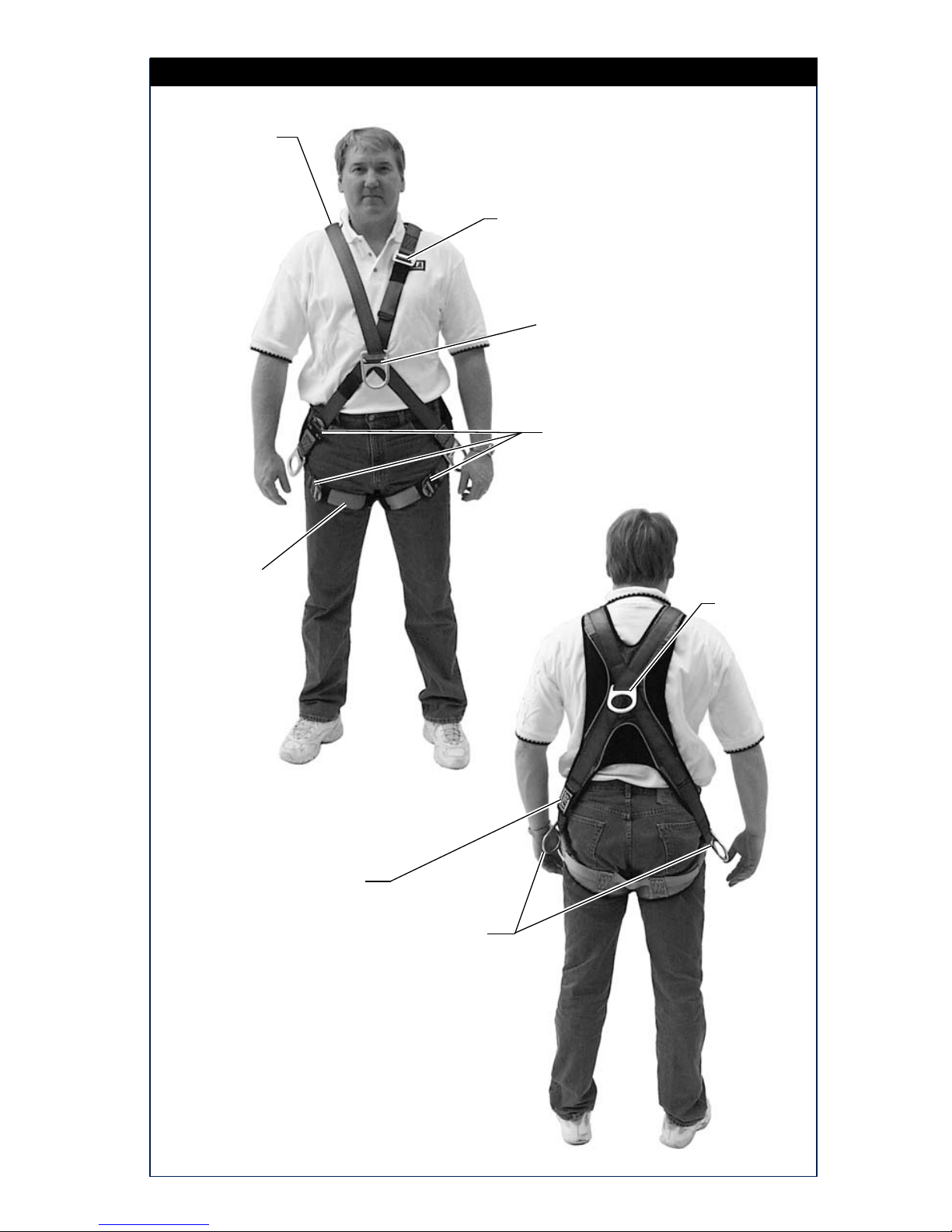
Figure 9 - Front and Back View of ExoFit Vest Style Full Body Harness
Front Back
Belt Loops

14
3.1 BEFORE EACH USE of this equipment inspect it according to
section 5.0 of this manual.
3.2 PLAN your system before use. Consider all factors that will affect
your safety during use of this equipment. The following list gives
important points to consider when planning your system:
A. ANCHORAGE: Select an anchorage that meets the
requirements specified in sections 1.2 and 2.5.
B. SHARP EDGES: Avoid working where system components
may be in contact with, come in contact with, or abrade
against, unprotected sharp edges.
C. AFTER A FALL: Any equipment which has been subjected
to the forces of arresting a fall or exhibits damage
consistent with the effect of fall arrest forces as described in
section 5.0, must be removed from service immediately and
destroyed by the user, the rescuer, or an authorized person.
D. RESCUE: The employer must have a rescue plan when
using this equipment. The employer must have the ability to
perform a rescue quickly and safely.
3.3 DONNING AND FITTING THE HARNESS:
A. ExoFit Vest Style Full Body Harness: See Figure 9 for
front and back views of the ExoFit Vest style full body
harness. Your harness incorporates loops for a removable
waist belt. The belt can be installed through the two loops in
the harness located in the lower back shoulder straps. The
belt will pass through the harness just below the padded
area. The hip pad, if used, is secured to the belt by passing
the belt through the hip pad loops.
Don the ExoFit Vest style full body harness by following
these steps (see Figures 10 and 11):
Step 1. Locate back D-ring held in position by the D-ring pad; lift
up harness and hold by this D-ring. Ensure the straps are
not twisted.
Step 2. Grasp the shoulder straps and slip the harness onto one
arm. The D-ring will be located on your back side. Ensure
that the straps are not tangled and hang freely. Slip
your free arm into the harness and position the shoulder
straps on top of your shoulder. Ensure that the straps are
not tangled and hang freely. The chest strap, with quick
connect buckle, will be positioned on the front side when
worn properly.
Step 3. Reach between your legs and grasp the gray leg strap
on your left side. Bring the strap up between your legs
and connect it by inserting the tab of the buckle into

15
Figure 10 - Donning ExoFit Vest Style Full Body Harness
Step 3
Step 1
Step 2
Step 3
Step 4 Step 5

16
receptor of quick connect buckle on the left side as shown
in Figure 10. You will hear a click when the tab engages
properly. Connect the right leg strap using the same
procedure. Pull the free end of the strap away from the
buckle to make a snug t on each leg strap. To loosen the
leg strap, grasp the yellow plastic portion of the buckle
and pull away from your leg to allow the strap to pull
through the buckle. A plastic end keeper on the end of the
strap will stop it from pulling completely out of the buckle.
To release the buckle, press the silver-colored tabs on the
buckle towards each other with one hand, while pulling on
the tab portion of the buckle with the other hand.
Step 4. Attach the chest strap by inserting the tab of the buckle
into the receptor of the quick connect buckle. You will
hear a click when the tab engages properly. The chest
strap should be 6 in. (15 cm) down from the top of your
shoulders. Pass excess strap through the loop keepers.
The strap may be tightened to a snug t by pulling the
free strap end to the left
(away from the buckle).
To loosen the chest strap,
grasp the yellow plastic
portion of the buckle and
pull away from the body
to allow the strap to pull
through the buckle. A
plastic end keeper on the
end of the strap will stop
it from pulling completely
out of the buckle. To
release the buckle, press
the silver-colored tabs on
the buckle toward each
other with one hand, while
pulling on the tab portion
of the buckle with the other
hand.
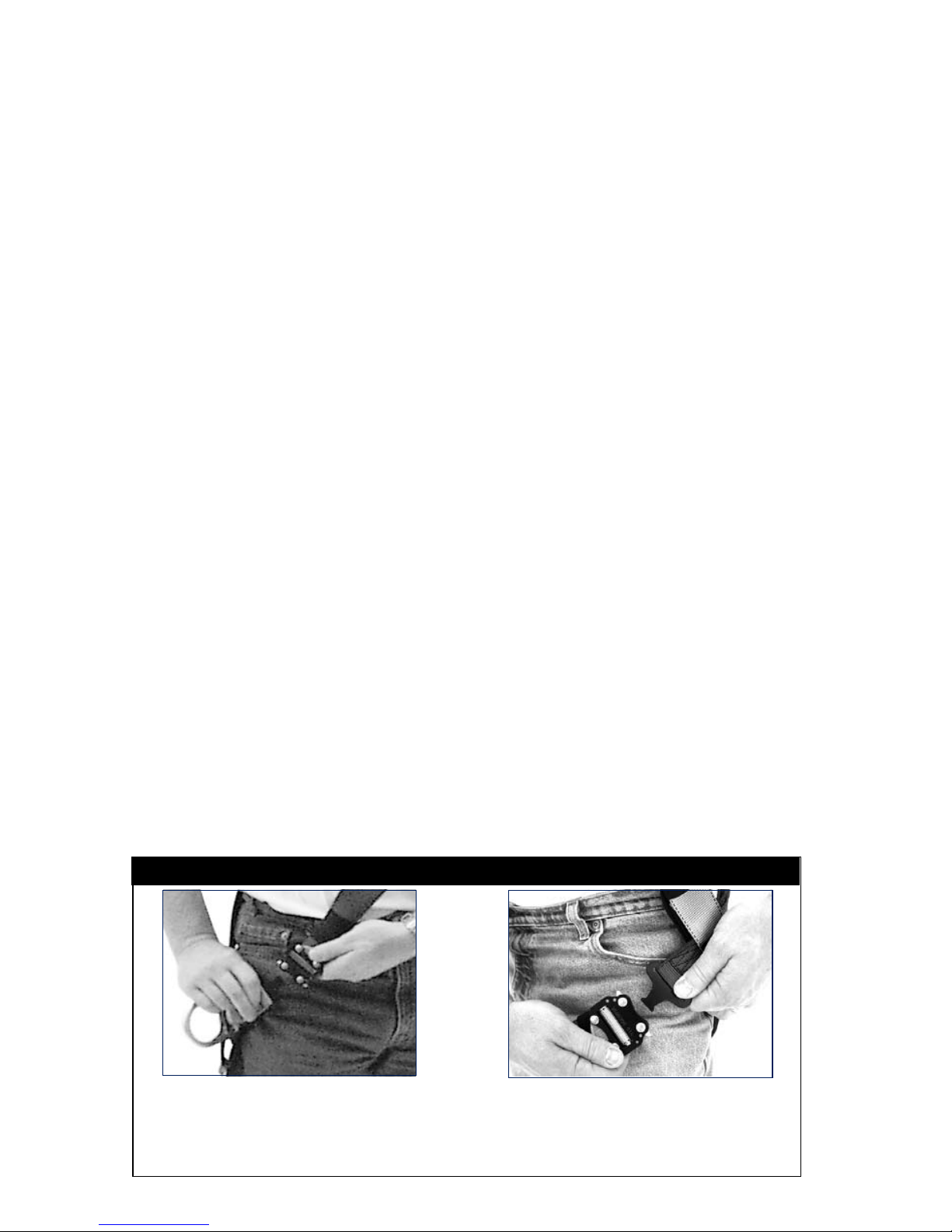
Figure 11 - ExoFit Quick Connect Buckle Connections
Chest Strap: Attach chest strap by
inserting the tab of the buckle into
the receptor of the quick connect
buckle until a click is heard
Leg Straps: Attach leg strap by
inserting the tab of the buckle into
the receptor of the quick connect
buckle until a click is heard
Figure 12 - ExoFit Cross-Over Style
Belt Loops

17
Figure 13 - Donning ExoFit Cross-Over Style Full Body Harness
Step 1 Step 2
Step 4
Step 3
Step 5
18
Figure 14 - ExoFit Quick Connect Buckle Connections
Hip Strap: Attach chest strap
by inserting the tab of the
buckle into the receptor of the
quick connect buckle until a
click is heard
Leg Straps: Attach leg strap by
inserting the tab of the buckle
into the receptor of the quick
connect buckle until a click is
heard
Step 5. Adjust shoulder straps to a snug t by pulling excess
strap through the parachute buckles on each side of the
harness. Left and right sides of shoulder straps should be
adjusted to the same length and the chest strap should
be centered on your lower chest, 6 in. (15 cm) down from
shoulder. The front D-ring on the vest style harness is
moved up or down by adjusting the shoulder straps and
leg straps. Center the back D-ring between your shoulder
blades. Note: On ExoFit XP models, the back (dorsal)
D-ring can be repositioned up or down as needed for a
correct t. Adjust leg straps to a snug t. At least 3 in.
(8 cm) of webbing must extend past the buckle on the leg
straps. Adjust the waist belt (if present).
B. EXOFIT CROSS-OVER STYLE FULL BODY HARNESS:
Your harness incorporates loops for a removable waist
belt. The belt can be installed through the two loops in
the harness located in the lower back shoulder straps, see
Figure 12. The belt will pass through the harness just below
the padded area. The hip pad, if used, is secured to the
belt by passing the belt through the hip pad loops. Don the
ExoFit Cross-Over style full body harness by following these
steps (see Figures 13 and 14):
Step 1. Locate the back D-ring held in position by the D-ring pad;
lift up the harness and hold by this D-ring. Ensure the
straps are not twisted.
Step 2.
Grasp the shoulder straps between the back and front
D-ring and slip the harness over your head from the left
side. Position the shoulder straps on top of your shoulders.
Ensure that the straps are not tangled and hang freely. The
D-ring will be positioned on your back when worn properly.
Step 3. Grasp the tab of the buckle located at your right hip and
insert it into the receptor of the quick connect buckle,
see Figure 13. You will hear a click when the tab engages
properly.

19
Step 4. Reach between your legs and grasp the gray leg strap on
your left side. Bring the strap up between your legs and
insert the tab of the buckle into the receptor of the buckle
on the left side as shown in Figure 13. You will hear a click
when the tab engages properly. Connect the right leg strap
using the same procedure. Pull the free end of the strap
away from the buckle to make a snug t on each leg strap.
To loosen the leg strap, grasp the yellow plastic portion of
the buckle and pull away from your leg to allow the strap
to pull through the buckle. A plastic end keeper on the end
of the strap will stop it from pulling completely out of the
buckle. To release the buckle, press the silver-colored tabs
on the buckle towards each other with one hand, while
pulling on the tab portion of the buckle with the other hand.
Step 5. Adjust shoulder strap to a snug t by pulling excess strap
through the parachute buckle. Left and right sides of the
shoulder straps should be adjusted to the same length
and the front D-ring should be centered on your lower
chest. The back D-ring should be centered between your
shoulder blades. Note: On ExoFit XP models, the back
(dorsal) D-ring can be repositioned up or down as needed
for a correct t. Adjust the leg straps to a snug t. At least
3 in. (8 cm) of webbing must extend past the buckle on
the leg straps. Adjust the waist belt (if present).
3.4 USE OF FALL ARREST D-RING OR ATTACHMENT ELEMENT:
For fall protection applications connect to the D-ring or attachment
element on your back, between your shoulder blades. Side
D-rings, if present, are for positioning or restraint applications
only. Front D-ring, if present, is for ladder climbing or positioning.
For rescue, back or front D-rings may be used. D-rings on seat
sling are for work positioning or personnel riding.
3.5 MAKING CONNECTIONS: When using a hook to connect to an
anchorage or when coupling components of the system together,
ensure roll-out cannot occur. Roll-out occurs when interference
between the hook and mating connector causes the hook gate
to unintentionally open and release. Self-locking snap hooks and
carabiners should be used to reduce the possibility of roll-out. Do
not use hooks or connectors that will not completely close over the
attachment object. See subsystem manufacturer’s instructions for
more information on making connections.
3.6 CONNECTING SYSTEM COMPONENTS: After properly tting
the full body harness, the user may then connect to other system
components. Follow the guidelines in section 3.4 on selecting the
correct attachment element.
4.0 TRAINING
4.1 It is the responsibility of the purchaser and the user of this
equipment to assure that they understand these instructions and

20
Detail of Label Packet with
i-Safe RFID Tag
Labels
i-Safe
RFID
Tag
Wrap
around
cover
Figure 15 - i-Safe™ RFID tag
are trained in the correct care and use of this equipment. They
must also be aware of the operating characteristics, application
limits, and the consequences of improper use of this equipment.
IMPORTANT: Training must be conducted without exposing the user
to a fall hazard. Training should be repeated on a periodic basis.
5.0 INSPECTION
5.1 The i-Safe™ RFID tag on this harness can be used in conjunction
with the i-Safe handheld reading device and the web based portal
to simplify inspection and inventory control and provide records for
your fall protection equipment. See Figure 15.
5.2 FREQUENCY: Before each use inspect the full body harness
according to sections 5.3 and 5.4. The harness must be inspected
by a competent person, other than the user, at least annually.
Record the results of each formal inspection in the inspection and
maintenance log in section 10.0, or use the i-Safe™ inspection
web portal to maintain your inspection records. If you are a rst-
time user, contact a Customer Service representative in the US
at 800-328-6146 or in Canada at 800-387-7484 or if you have
already registered, go to: www.capitalsafety.com/isafe.html. Follow
Other manuals for Exofit
1
This manual suits for next models
1
Table of contents
Popular Accessories manuals by other brands


Waterpik
Waterpik WF-20 Series user manual

Little Labs
Little Labs multi z pip rev.b Operator's manual

S+S Regeltechnik
S+S Regeltechnik Thermasgard ALTF 1 Operating Instructions, Mounting & Installation

Veris Industries
Veris Industries AG01E installation guide

ABB
ABB ABB-free@home WBI-S-1-xx-WL Series product manual

PCB Piezotronics
PCB Piezotronics 333B40 Installation and operating manual


