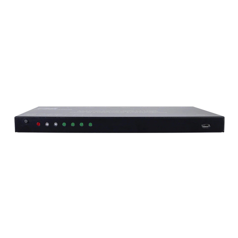
DCB PAS v2 User manual

PAS v2
Priority Audio Switch
User’s Guide
Version 2, Revision C
Revised Nov 25, 2019
Version 2.0c

TABLE OF CONTENTS
Certifications..............................................................2
FCC Statement...............................................................2
RoHS..............................................................................2
Chapter 1 Introduction..............................................3
Package Contents...........................................................3
P S Hardware Specifications........................................4
Chapter 2 Installation and Confi uration................5
Overview........................................................................5
Chapter 3 Connectors................................................6
Power Connector............................................................6
RJ-45 E&M Connection Pin-outs..................................7
Revision &B RJ45 Pin ssignments...........................8
Connection details..........................................................8
Chapter 4 Operation..................................................10
Common Uses................................................................10
Operation Details............................................................10
Cascaded P S................................................................11
Indicator LED's..............................................................11
Chapter 5 Troubleshootin ........................................12
Hardware Problems........................................................12
Appendix A Specifications.........................................13
P S Specification...........................................................13
Appendix B Warranty................................................14
DCB Product Two Year Limited Warranty..................14
Appendix C Schematic...............................................15
Revision C Reference Schematic...................................15
Appendix D Accessories.............................................16
Mounting Options..........................................................16
i

Certifications
FCC Statement
This device complies with the limits for a Class digital device, pursuant to Part 15 of the FCC rules.
This equipment has been tested and found to comply with the limits for a Class digital device pursuant
to Part 15 of the FCC Rules. These limits are designed to provide reasonable protection against harmful
interference when the equipment is operated in a commercial environment. This equipment generates, uses,
and can radiate radio frequency energy and if not installed and used in accordance with the instruction
manual may cause harmful interference to radio communications.
Operation of this equipment in a residential area is likely to cause harmful interference, in which case the
user will be required to correct the interference at the user's own expense.
Copyright 2019 ll rights reserved.
ll trademarks and trade names are the properties of their respective owners.
RoHS
Some models of this product are available in RoHS versions.
2

Chapter 1
Introduction
This chapter provides an overview of the PAS features and capabilities.
The Priority udio Switch (P S) is designed to be installed between a transmitter site and
two control operator positions so they can share a single transmitter. The P S takes in two
4-wire audio lines each with a Push-to-Talk (PTT) lead where PTT is activated by shorting
this lead to ground. The ports are designated as Priority and Secondary. The Priority port
will seize control of the audio channel when its PTT lead is shorted to ground, otherwise the
Secondary ports audio channel and PTT state are passed through to the output port.
The P S contains two completely isolated instances of the priority switching function.
The standard P S is powered by 48VDC, which matches most telco systems. External
power supplies are available for C or other DC power operations.
Receive audio and other return leads from the transmitter are always passed back to both
controllers.
Input Ports Power and Output Ports
Package Contents
You should find the following items packaged with your P S product:
The P S unit
Optional power supply (if ordered)
If any of the above are missing, contact your dealer immediately.
3

PAS Hardware Speci ications
Connectors
•One 48 VDC power port
•Four RJ-45 audio input ports
•Two RJ-45 audio output ports
•Two audio input ports are paired with each audio output port
Controls
• There are no user software controls. The unit is operational upon power application.
Environmental
•Operation: -25° C to +65° C, non condensing humidity
Physical / Electrical
•5 ¼ x 5 ½ x 1 ¾ Inches
•Power requirements: 48 VDC, which may be supplied by a 120 V C power adapter
•One pound unit weight
4

Chapter 2
Installation and Configuration
Overview
The P S is connected between two audio sources and a single audio receiving device. There are two
instances of this operation, and they may be cascaded to allow for three inputs to a single transmitter, or
used independently with two inputs to each of two transmitters. It is usually installed at a transmitter site to
allow automatic operation by multiple control operators of the transmitter.
ll connections to the P S use RJ-45 connectors or the power connector screw terminals.
udio Source Connections:
Switched Transmit Audio Flow
Received audio from the transmitter is always passed to pins 3 & 6 of both priority and secondary devices.
5

Chapter 3
Connectors
Power Connector
Green screw connector (numbered right to left)
Pin 1 -48 VDC
Pin 2 Chassis ground
Pin 3 +48 VDC
6

RJ-45 E&M Connection Pin-outs
The following table shows the PRIMARY, SECONDARY and OUTPUT po t pin assignments. The
OUTPUT po t Audio Out signals on pins 1 and 2 a e switched between PRIMARY and
SECONDARY po t based on the PRIMARY po t PTT (E1) input on pin 4. The two ight most
columns show the OUTPUT signals when PRIMARY PTT input is OPEN and SHORTED to GND.
PRIMARY RJ45 RJ45
OUTPUT
PRI PTT (E1) Open
OUTPUT
PRI PTT (E1) GND
Audio In (R1) 1 1 Audio Out (R2) Audio Out (R1)
Audio In (T1) 2 2 Audio Out (T2) Audio Out (T1)
Audio Out (R) 3 3 Audio In (R) Audio In (R)
PTT In (E1) 4 4 PTT Out (E2) PTT Out (E1) GND
SG/EB (GND) 5 5 SG/EB (GND) SG/EB (GND)
Audio Out (T) 6 6 Audio In (T) Audio In (T)
M 7 7 M M
SB/MB 8 8 SB/MB SB/MB
SECONDARY RJ45
Audio In (R2) 1
Audio In (T2) 2
Audio Out (R) 3
PTT In (E2) 4
SG/EB (GND) 5
Audio Out (T) 6
M 7
SB/MB 8
7

Revision A&B RJ45 Pin Assignments
This table shows the cu ent RJ45 pin numbe s in the left hand column and the olde Rev B pin
numbe s in the fa ight column. The signal di ections a e noted in the PRI/SEC and OUTPUT
columns. This table is included only or re erence with products produced prior to
Revision C. Do not use this table unless you are replacing a previous version and
connecting the older PAS cables to a Revision C unit.
Rev C
RJ45 Signal PRI/SEC OUTPUT
Rev B
RJ45
1 Audio In (R1) IN OUT 6
2 Audio In (T1) IN OUT 3
3 Audio Out (R) OUT IN 5
4 PTT (E) IN OUT 7
5 SG/EB (GND) GND GND 8
6 Audio Out (T) OUT IN 4
7 M OUT IN 2
8 SB/MB OUT IN 1
Connection details
The P S was originally designed to be placed in between a Loop channel bank and a transmitter connected
to it via an E&M Card.
Loop Telecom channel banks (V4200, AM3440, O9500, O9550, IP6704A) with 8EM, 8EMA or
QEMA cards
To connect a Loop channel bank E&M card (LEM) to the priority and/or secondary ports of the P S,
configure the LEM to operate in B-Side mode and connect with the proper RJ45 cable.
To connect to a LEM on the output side port of the P S, configure the LEM card to operate in -Side
mode and connect with the proper RJ45 cable.
Since the P S always uses the “E lead” for PTT indicator and E-Lead PTT is always done via connection
to ground, all E&M types are supported in LEM and will pass through the P S when the LEM cards are
properly configured for -side and B-side.
Charles Industries channel banks with 3652-80 and 3652-81 E&M Cards
To connect to a Charles channel Bank E&M card (CIEM), build an RJ45 cable that connects to the specific
pins on the 50 pin Telco connector (or connectors for 3252-80) for the channels that you wish to use.
To connect a CIEM to the priority and secondary ports of the P S connect the following pins to the pins in
a straight-through fashion. That is M to M, R to R, etc. The pattern is:
Pin 8 to MB, Pin 7 to M, Pin 2 to T1, Pin 6 to T, Pin 3 to R, Pin 1 to R1, Pin 4 to E and Pin 5 to EB
8

If you are connecting a CIEM to the output side ports of the P S, then you must cross over the signals and
you can only use E&M Types 4 & 5. This is because CIEM can only accept PTT input on the M-Lead, the
P S only can only signal PTT by closure to ground, and E&M types 4 & 5 are the only E&M types where
PTT is signaled by closure to ground on the M lead. The pattern is:
Pin 8 to EB, Pin 7 to E, Pin 2 to T, Pin 6 to T1, Pin 3 to R1, Pin 1 to R, Pin 4 to M and Pin 5 to MB
Other channel banks
Connections to other channel banks and E&M devices can be made by following the directions of the
signals in the chart above to connect to your device. Remember that the P S input ports can only use
closure to ground to detect PTT and the unit passes the PTT state out only via closure to ground. This
required that choose an appropriate E&M type that signals PTT or accepts PTT based on closure to ground.
Groundin
Remember that grounding is critical with E&M signaling, so you must either connect the P S using the
center pin of the power supply terminal to the same ground plane as your other equipment (when using
E&M type 1 or E&M type 5) or you must connect pin 5 of the RJ45 (SG or EB lead) to the ground plane of
your equipment (When using E&M type 2-4).
9

Chapter 4
Operation
This chapter explains how to use the PAS.
Common Uses
The application below shows the P S used with Loop M3440 channel banks for remote control of a
transceiver from two different locations. Push to talk at the controller positions on the left is passed across
the link using E&M signaling. One of the two positions is priority, the other one is secondary. The receive
audio is always passed back from the radio to both controllers.
Operation Details
OUT Pins 6 and 3 are always bridged to both PRIORITY and SECOND RY pins 6 and 3. This allows
audio input from the OUT port to flow back to the PRIORITY and SECOND RY port.
OUT pins 8 and 7 are also always bridged to both PRIORITY and SECOND RY input pins 8 and 7. This
is allows M and SB/MB leads from the OUT side to flow back to the PRIORITY and SECOND RY port..
While PRIORITY port pin 4 is grounded to chassis (PTT activated), OUT pin 4 is grounded to chassis
(PTT to the transmitter), PRIORITY pins 2and 1 are connected to OUT pins 2 and 1(audio input from the
PRIORITY port sent to the transmitter).
While PRIORITY port pin 4 is open (PTT not activated), OUT pin 4 is connected to SECOND RY pin 4
(forwarding the state of the SECOND RY PTT), and SECOND RY pin 2 and 1 are connected to OUT
pins 2 and 1 (audio input from the SECOND RY port sent to the transmitter)
10

Note:
When the P S is un-powered, the audio path from secondary is connected to the output. It becomes a pass-
through of the secondary port in the event of power loss.
Cascaded PAS
The two “sides” of a P S may be combined to make a three-input/one-output P S instead of two
independent two-input/one-output unit.
Connect a RJ45 straight-through cable from 1-OUT to 2-SECOND RY. Connect a RJ45 cable between
OUT-2 and the transmitter.
Port 2 PRIORITY now has the highest precedence and will always assert audio control if pin 4 of this port
is grounded.
Port 1 PRIORITY has the next highest precedence and will assert audio control if pin 4 of this port is
grounded and port 2 PRIORITY is not.
Port 1 SECOND RY will the the default port and it will pass its pin4 state and audio unless one of the
other ports is grounded.
Indicator LED's
The P S is equipped with green and amber LED lights next to each PRIORITY and SECOND RY port..
When the unit is powered on and the PRIORITY port is not keyed the green LED light next each
SECOND RY RJ45 port will be illuminated. When either PRIORITY port is keyed then the green LED
light next to that PRIORITY RJ45 will illuminate and the SECOND RY RJ45 light will go out. The
amber LED lights are not used.
11

Chapter 5
Troubleshooting
This chapter explains how to troubleshoot the PAS.
If the P S does not function properly, please contact your dealer for further assistance.
Hardware Problems
Before anything else, check that all cables are wired correctly and properly connected and make sure you
have proper grounding for all equipment.
Since this is a specialty device and should be deployed by knowledgeable technicians, please contact DCB
technical support if there is any problem installing or maintaining the unit.
12

Appendix A
Specifications
PAS Speci ication
One 48 VDC power port
Two RJ-45 input connectors for each channel (total of 4)
One RJ-45 output connector for each channel (total of 2)
Environmental: Operation -25° C to +65° C C non-condensing humidity
Dimensions: 5 1/4” x 5 ½” x 1 3/4”
Power: 48 VDC
13

Appendix B
arranty
DCB Product Two Year Limited Warranty
DCB products are warranted to be free of defects in materials and workmanship for two years. Data
Comm for Business, Inc. will repair or replace any equipment proven to be defective within the warranty
period. ll warranty work is F.O.B. Dewey, IL. This warranty is exclusive of abuse, misuse, accidental
damage, acts of God or consequential damages, etc. DCB liability shall not exceed the original purchase
price.
ll equipment returned for repair must be accompanied by a Returned Material uthorization (RM )
number. To receive an RM number, call (217) 897-6600 between the hours of 8 M and 5 PM Central
Time. Equipment must be shipped prepaid to DCB and will be returned at DCB's expense.
Ship returned items to:
Data Comm for Business
2949 County Road 1000E
Dewey, IL 61840
TTN: RM #
14

Specifications
Appendix C
Schematic
Revision C Re erence Schematic
15

Appendix D
Accessories
Mounting Options
The P S has an optional front bezel / shelf that can be used to mount either 1 or 3 P S units in a 1U 19
inch rack space.
Order part number 9902095 to hold 3 P S and 9902096 for single unit.
n C to DC adapter for a single unit (300m ) .is available as part number 9001176
single C adapter that can be used with 3 units (1.3 ) is part number TBD
16
Table of contents
Popular Switch manuals by other brands
Generac Power Systems
Generac Power Systems RTS Technical manual

Europa components
Europa components LBC160-2503PSNME manual

Gems
Gems FS-600 Series Operating and installation instructions
Extreme Networks
Extreme Networks Summit 300-48 Software user's guide
Stromag
Stromag 51 Series Translation of the original assembly instruction
iBall Baton
iBall Baton iB-LGDS18G user guide
