DCS RF151 Training manual


A MESSAGE TO OUR CUSTOMERS
Thank you for selecting this DCSIce Maker. Because of this appliance's unique features, we have developed this Use and Care
and Installation Guide. It contains valuable information on how to properly install, operate, and maintain your new appli-
ance for years of safe and enjoyable operation.
To help serve you better, please fill out and submit your Product Registration by visiting our website at
www.dcsappliances.com and selecting"Customer Care"on the home page and then select"Product Registration". In
addition, keep this guide handy, as it will help answer questions that may arise as you use your new appliance.
For your convenience, product questions can be answered by a DCSCustomer Care Representative at 1-888-936-7872, or
NOTE: Please write the Model, Code, and Serial Numbers on this page for references (the serial plate is located on the lower
right side of the inside front panel. See Fig. 02.).
MODEL NUMBER
CODE
SERIALNUMBER
NOTE: Inspect the product to verify that there is no shipping damage. If any damage is detected, call the shipper and initiate
a damage claim. DCS by Fisher & Paykel is not responsible for shipping damage.
DO NOT discard any packing material (box, pallet, straps) until the unit has been inspected.
PLEASE RETAIN THIS MANUAL FOR FUTURE REFERENCE.

TABLE OF CONTENTS
SAFETY PRACTICESAND PRECAUTIONS 3
UNPACKING YOUR ICEMAKER 4
PARTSIDENTIFICATION 5
INSTALLATION
Select location 6
Cabinet clearance 6
Leveling legs 6
Electrical connection 6
Grounding method 6
Drain plumbing 7
Water supply 7
OPERATION 8
CARE AND MAINTENANCE
Care of the unit 9
Cleaning your unit 9
Preparing the ice maker for storage and winterizing 10-11
Things to remember 12
Help prevent tragedies 12
TROUBLESHOOTING 13-16
SERVICE 17
WARRANTY 18-19

SAFETY PRACTICES & PRECAUTIONS
[]
[]
[]
[]
[]
To reduce the risk of fire, electric shock, or injury to persons read these SAFETY PRACTICESAND PRECAUTIONSbefore operat-
ing this appliance. Usethis appliance only for its intended purpose as described in this User Guide.
WARNING
When using this appliance always exercise basic safety precautions including the following:
DANGER!
This appliance is not intended for use by young children or infirm persons without supervision.Young children should be
supervised to ensure they do not play with the appliance.
Risk of child entrapment. Before you throw away your old ice maker:
1. Take offthe doors.
2. Leave the shelves in place so that children may not easily climb inside.
ELECTRICAL
This appliance must be properly installed in accordance with the installation instruction before it is used.
Never unplug your ice maker by pulling on the power cord. Always grip the plug firmly and pull straight out from the outlet.
Repair or replace immediately all electric service cords that have become frayed or otherwise damaged. Do not use a cord
that shows cracks or abrasion along its length or at either the plug or appliance end. If the power supply cord is damaged,
it must only be replaced by your Fisher & Paykel Appliances Authorized Service Center because special purpose tools are
required.
[] Unplug your ice maker before cleaning, or replacing the light bulb.
STORING FOOD AND DRINKS
[] Never store volatile or flammable materials in your ice maker asthey may explode.
[] Never freeze liquids in glass containers. Liquid expands during freezing which may cause the container to explode.
[] Do not consume food if it istoo cold. Food removed from the ice maker may be cold enough to cause damage when brought
into contact with bare skin, e.g.frozen ice cubes.
[]
[]
[]
CLEANING
Many commercially available cleaning products contain solvents which may attack plastic components of your ice maker and
cause them to crack. Please refer to the Care and Maintenance section of this booklet for further advice (see pages 9
and 11).
DISPOSAL
Extreme care must be taken when disposing of your old appliance to avoid hazards.The refrigerant gas must be safely
removed.
Your Fisher & Paykel Appliances Authorized Service Center will be able to give advice on environmentally friendly methods of
disposing of your old ice maker.

UNPACKING YOUR iCE MAKER
REMOVE PACKAGING
Your ice maker has been packed for shipment with all parts that could be damaged by movement securely fastened. Before
using, be sure all packing materials and tape have been removed.
IMPORTANT
Keep your carton packaging until your ice maker has been thoroughly inspected and found to be in good condi-
tion. If there is damage, the packaging will be needed as proof of damage in transit.
NOTE: Inspect the product to verify that there isno shipping damage. If any damage isdetected, call the shipper and initiate
a damage claim. DCS by Fisher & Paykel isnot responsible for shipping damage.
DO NOT discard any packing material (box, pallet, straps) until the unit has been inspected.
SPECIFICATIONS
Exterior Cabinet Dimensions:
Height
Width
Depth
Shipping Weight:
Electrical Requirements:
You need to have the
following materials for
proper installation:
Water supply:
Drain:
Drain Pump (optional):
Ice Capacity:
34-1/4" min.
14-7/8"
21-1/2"
100 Ibs.
115VAC/60Hz
1/4"OD copper tubing,
_14- 7/8"
34-1/4" min.
21-1/2"
Fig. 01
SUPP_
JLINE
shut-offvalve and 5/8"1D rubber drain tube
1/4"OD copper tubing (subject to local codes), 20-100 PSI.For water connection, allow 2"
behind the unit.
5/8" ID rubber tube (subject to local codes). Unit must drain into a 1-1/2" ID minimum stand
pipe.
RF151-P
up to 35 Ibs. per day (75° Fambient)

PARTS iDENTiFiCATiON
Evaporator---_
Distributor
.",,°\ \ °I,x
\
Makeserethatdistributor
tubingisnotinthepath
oftheiceslab
Escutcheon/
FrontCoverPanel
Ice
IceScoop
BinLevel
Scoop
SerialPlate
Location
SelectorSwitch
Eva_
--L J
ReservoirDrainPlug
Fig. 02

iNSTALLATiON
SELECT LOCATION
The proper location will ensure peak performance of your appliance. Choose a location where the unit will be out of rain
and direct sunlight and away from heat sources. Best performance will be maintained when installed within the following
parameters:
IDEAL AMBIENT TEMPERATURE RANGE_
Built-In 55-80 degrees F
Freestanding 55-90 degrees F
_lce Maker will not perform correctly in ambient temperature less than 55 degrees F,
CABINET CLEARANCE
Ventilation is required from the bottom front section of the unit where the grill
is located. Keep this area open and clear of any obstructions.
Adjacent cabinets and countertop can be built around the unit as long as no
top trim or countertop is installed lower than the top of the hinge.The unit
must be able to be removed from the cabinet for service.
SIDE TRIM INSTALLATION:
Attach side trim to the inner side of the cabinet so that the trim faces outward
(away from the appliance's door) and fasten with appropriate screws suitable
for the type of cabinet material.
LEVELING LEGS
Make certain your ice maker islevel. Adjustable legs at the front corners of the
unit should be set so the unit isfirmly positioned on the floor and the front is
raised just enough so that the door closes easily when opened about halfway.
Turn leveling legs clockwise to raise unit, counterclockwise to lower it.
ELECTRICAL CONNECTION
Check the serial nameplate for the correct power supply. Use only the electri-
cal power supply specified on the serial nameplate (the serial plate is located
on the lower right side of the inside front panel- see Fig. 02). DO NOT USEAN
EXTENSION CORD.
Island Preparation
24rain:'
34-114"rain.
to3Smax.
SideTrim Installation _________-
Fig. 03
GROUNDING METHOD
This product isfactory equipped with a power supply cord that has a three-pronged,
grounded plug. It must be plugged into a mating grounding type receptacle in accor-
dance with the National Electrical Code and applicable local codes and ordinances (see
Fig. 04. If the circuit does not have agrounding type receptacle, it is the responsibil-
ity and obligation of the customer to exchange the existing receptacle in accordance
with the National Electrical Code and applicable local codes and ordinances. The third
ground prong should not, under any circumstances, be cut or removed. All U.L. listed
refrigerated products are equipped with this type of plug.
WARNING
This unit should not, under any circumstances, be ungrounded. Fig. 04

iNSTALLATiON
[]
[]
[]
[]
[]
[]
[]
[]
DRAIN PLUMBING
Your ice maker uses a gravity drain (Fig. 05) that requires 5/8" I.D. tubing from the back of the ice maker to a plumbed
connection to a sanitary sewer. Remove the access panel to plumb in drain connection. Gravity drain location for built-in
units can be within the area shown in Fig. 07. An optional drain pump (RF151-P)(Fig.06) can be purchased for your ice maker
if a gravity drain is not accessible.
Observe and follow all local codes when installing ice
maker.
WARNING
Failure to use an adequate drainage system will
result in surrounding water damage and/or poor
ice production.
WATER SUPPLY
The ice maker must be connected to a potable, active
cold water supply line delivering water pressure at a
minimum of 20 psi and a maximum of 120 psi.
Water connection is made through a right angle
garden hose style fitting supplied with the ice maker.
See"garden hose style fitting"for a detailed instruc-
tion sheet. DO NOT USEANYTHREAD SEALERS.
A water filter can be used with this unit. A quality
filter can help remove particles as well as remove
taste and odors from water and prolong life.
DO NOT USEA"REVERSE OSMOSIS" FILTERINGDEVICE.
Softened water is not recommended. This will
produce soft, cloudy ice cubes that will stick together.
De-ionized water is not recommended. This water will
not form solid ice cubes.
A water specialist can recommend proper water treat-
ment.
After installation of water line, turn on water and
check for any leaks. Additional tightening may be
needed.
Allow for extra water line for built-in installations for
easy removal of unit and to help prevent the water
line from kinking.
FrontofUnit
5/8inchI.D.
DrainTubingand
HoseClamp
1/2"DrainPipe
Drain
IceMochine PowerCord
Fig. 05
,liedScrews
Tubegoesthruthis
openingintheAccessPanel.
DrainPum
PowerCord
VentTubegoesthruthisopenin!
intheAccessPanel.
Fig. 06
Panel
6.75
TopofUnit
21.50
GravityDrainLocation
3814.75
Fig. 07

OPERATION
Your ice maker isunique in forming ice. It uses fractional freezing to form a slab of ice that isclear and has less mineral
content than the water it is produced from. This is accomplished by running water over the cold evaporator plate which
gradually freezes the water to produce the ice slab. Mineral deposits are left in the reservoir.
When the ice slab reaches the correct thickness determined by the temperature of the evaporator plate, the electronic
control switches to the harvest cycle to harvest the ice. During the harvest cycle, the ice slab falls from the evaporator to the
ice grid cutter. Here, the ice slab is cut into 3/4"squares by the grid cutter's heated wires. During the harvest cycle, the drain
valve will remain open for 45 seconds to drain the reservoir of remaining deposits. After that, the water valve will open for
two (2) minutes providing two (2) quarts of water to the reservoir for the next production cycle.
The ice maker will keep producing ice until the ice maker's bin isfull and will restart automatically when ice needs to be
replenished in the bin.
5/8I.D.Drain
TubingBerb
MakeCertainAllHose
ClampsAreSecure
RearofUnit
° f FiNing
z_ ConlpressionFitting
1/4 inch
Tubingfrom
ColdWaterLine_
GardenHeseStyle
/
i
5.50
Fig. 08

CARE AND MAINTENANCE
CAREOF THE UNiT
A. Avoid leaning on the unit's door. You may bend the door hinge or tip the unit.
B. Exercise caution when sweeping, vacuuming or mopping near the front of the unit. Damage to the grill and/or switch
can occur.
C. Periodically clean the inside of the ice maker components and inside of the unit. Unplug the maker prior to doing so.
D. Periodically check and/or clean the front grille and condenser coils as needed.
E. Your ice maker has a stainless steel door and cabinet.To keep it looking at its best, we recommend periodically applying a
stainless steel cleaner and a non-abrasive stainless steel polish. This is especially important for outdoor applications and
locations near salt-water environments.
CLEANING YOUR UNIT
Some impurities will remain and build up in the ice maker and stick to the ice maker's parts over time. This build-up must
be removed for proper ice production, ice quality, and ice maker life. Your ice maker isequipped with a cleaning mode that
will help in cleaning out these impurities. This build-up of impurities will need to be cleaned regularly (at the very least,
annually), depending on use and water hardness. You can use an acid such as one specified for ice maker cleaning oryou
can use citric acid to remove the build-up. To clean the ice maker:
A. Switch the selector switch to the"OFF" position.
B. Remove the drain plug at the bottom of the reservoir to drain any remaining water and then reinstall.
C. Add the recommended cleaning solution to the reservoir of the ice maker. Access to the reservoir can be obtained
by removing the front panel screws and the front panel. Determine the proper amount of cleaner from the ice maker
cleaner manufacturer's mixture ratio based on three (3) quarts of water (refer to the manufacturer's directions).
D. Replace the front cover panel and close the door.
E. Switch the selector switch on the grille of the ice maker to the"CLEAN" position. Three (3) quarts of water will automati-
cally be added to the cleaning solution.
F. The total cleaning time will end in 49 minutes. The cleaning cycle will automatically rinse the evaporator plate and also
drain the cleaning solution and rinse with water.
G. After the cleaning cycle has ended, remove the front panel again and check that the build-up has been removed. The
evaporator plate should be clean, shiny, and smooth to the touch. If build-up is still visible, repeat the cleaning cycle
above. If build-up is removed, continue below.
H. Remove the distributor tube, hose clamp, hose and its rubber ends.
J.
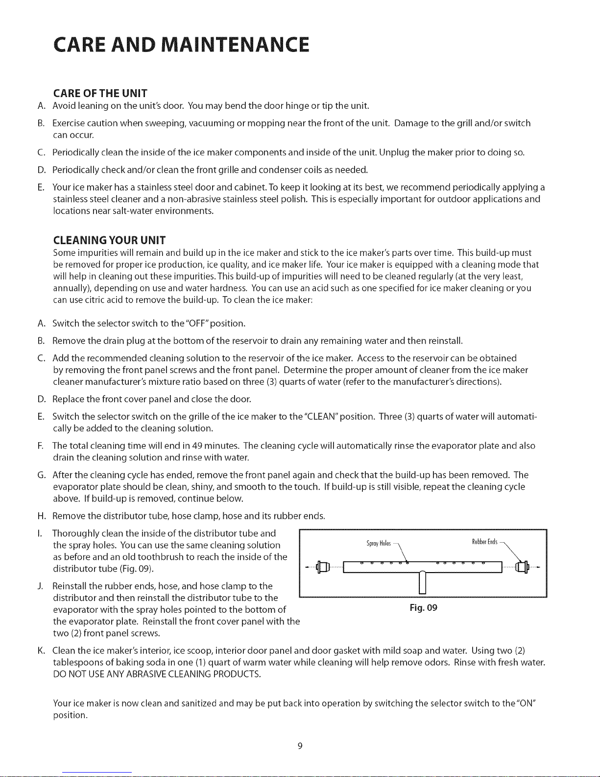
Thoroughly clean the inside of the distributor tube and
the spray holes. You can use the same cleaning solution
as before and an old toothbrush to reach the inside of the
distributor tube (Fig. 09).
Reinstall the rubber ends, hose, and hose clamp to the
distributor and then reinstall the distributor tube to the
evaporator with the spray holes pointed to the bottom of
the evaporator plate. Reinstall the front cover panel with the
two (2) front panel screws.
SprayHoles X RubberEnds_
Fig. 09
K. Clean the ice maker's interior, ice scoop, interior door panel and door gasket with mild soap and water. Using two (2)
tablespoons of baking soda in one (1) quart of warm water while cleaning will help remove odors. Rinse with fresh water.
DO NOT USE ANY ABRASIVE CLEANING PRODUCTS.
Your ice maker is now clean and sanitized and may be put back into operation by switching the selector switch to the"ON"
position.

CARE AND MAINTENANCE
PREPARING THE iCE MAKER FOR STORAGE AND WiNTERiZiNG
If the ice maker ismoved, not used for an extended period of time, or will be in an area that will be near freezing tempera-
tures, it is necessary to remove any remaining water in the ice-making system.
CAUTION
This ice maker must have all water drained and removed to prevent ice maker damage as well as possible water
damage to the surrounding area in freezing conditions. These damages are not covered under warranty.
WARNING
Do not use any type of anti-freeze or other solution as a substitution for properly draining the ice maker.
CLEAN THE ICE MAKER
Cleaning the ice maker will help prevent mold and mildew growth aswell as sanitize the unit for storage or when it is put
back into service.
A. Remove all ice from the ice storage bin.
B. Pull the reservoir drain plug to drain reservoir water.
C. Reinstall the drain plug after all of the water has drained.
D. Add ice maker cleaning solution to ice maker's reservoir.
E. Switch the rocker switch in the grill to CLEAN position.
F. The CLEAN cycle will complete in 49 minutes.
DRAINING AND REMOVING WATER FROM THE ICE-MAKING SYSTEM
A. Turn off water supply to the ice maker.
B. Disconnect the water supply fitting at the inlet of the water valve.
C. Switch the rocker switch to CLEAN for approximately one (1) minute. This will energize and open the water valve and
remove most of the water from the water valve and the water valve's outlet water line to the reservoir.
D. Switch the rocker switch to OFF position. This will energize and open the drain valve to drain the reservoir and the ice
maker's drain system.
E. Unplug the unit from the electrical outlet.
F. Remove the back panel from the rear of the unit.
G. Disconnect the water valve's outlet water line to the reservoir and drain the remaining water from the water line trap area.
H. Reconnect the water valve outlet water line and tighten the compression nut to a watertight seal.
I. Reinstall the unit's back panel.
J. Clean and dry the ice maker's storage bin.
K. Prop the door open for air circulation to prevent mold and mildew.
L. Leave the water supply line disconnected or reconnect the supply line and leave it shut off. DO NOT turn the water on
and allow water to enter back into the water valve.
10

CARE AND MAINTENANCE
PREPARING THE iCE MAKER FOR STORAGE AND WiNTERiZiNG
DRAiNiNG WATER FOR OPTIONAL DRAIN PUMP APPLiCATiONS
A. Remove the drain pump from the ice maker (refer to Drain Pump Installation Instructions).
B. Drain the water in the drain pump's reservoir by turning the pump upside down and allowing water to drain through the
pump's inlet and vent tube fittings.
C. After all water isdrained, reinstall the drain pump. Make certain all tubing is installed and all hose clamps are tight (refer
to Drain Pump Installation Instructions).
TO RESTART THE ICE MAKER
A. With the rocker switch in the OFF position, plug the unit into an electrical outlet.
B. Reconnect or turn on the water supply line.
C. Reconnect drain tubing if removed.
D. Turn the rocker switch to the ON position.
E. Check the water inlet, drain lines, and fittings for any water leaks.
F. Check drain pump (if equipped) operation by pouring approximately two (2) quarts of water into the ice storage bin. The
drain pump should activate and discharge water (refer to Drain Pump Installation Instructions). Check for water leaks at
all hose connections.
11

CARE AND MAINTENANCE
THINGS TO REMEMBER
[] Allow your ice maker to run for 24-48 hours to accumulate ice in the ice maker's bin.
[] Unit will cycle often between ice production and ice harvest cycles.
[] Your unit will automatically stop producing when the ice bin isfull.
[] Unplug your ice maker before working on the unit.
[] Keep your ice maker clean for proper ice quality, production, and unit life.
[] Room and water temperatures will greatly affect the output of ice in your unit (see table, Fig. 10). Ice will also melt away,
especially at the start of an empty bin, but melting will slow asice accumulates.
Production Rate
(LB/day) _ Approximate time to fill bin
(Hours) _
Water Temperature F
ii
50 ° 70 °
70 ° 341bs. 321bs. E
80 ° 301bs. 271bs. ,_
90 ° 23 Ibs. 201bs. E
<::
Water Temperature F
50 ° 70 °
70 ° 31 hrs. 34 hrs.
80 ° 41 hrs. 58 hrs.
90° 60 hrs. 82 hrs.
* Note:Dueto variablesininstallationand use,individualresultsmayvary.
Fig. 10
HELP PREVENT TRAGEDIES
Each year children die because they climb inside a discarded refrigeration product, get trapped inside and suffocate. Take
precautions to prevent such tragedies by removing the door or by taping or chaining it shut before discarding.
12

TROUBLE SHOOTING
PROBLEM
Unit does not operate.
Unit operates but does
not produce ice.
POSSIBLE CAUSE
1.The unit is unplugged.
2. Breaker is tripped or fuse is
blown.
3. Icemaker selector switch is
in the "OFF"position.
1.The unit hasjust been
started and it has been less
than 6 hours.
2. Typical ice production cycle
can take up to 1.5 hours.
Initial start-up cycles can be
longer.
3.The selector switch is in the
"OFF" or "CLEAN" position.
4. No water in the reservoir.
5. Distributor tube is
restricted.
6. Build-up of deposits on
evaporator plate.
7. Condenser fan air flow is
restricted.
8. Room and/or water temper-
ature is too warm.
9. Leaking drain valve.
10. Inadequate drain system.
11. Grid cutter is unplugged.
12.Circulation pump is
unplugged.
CORRECTION
Plug in the unit,
Reset breaker or replace fuse. Check to make sure
there is not a short in the electrical circuit.
Set the rocker switch on the grill of the ice maker to the
"ON" position.
ice produced when the unit is initially started will melt
off in the bin. Ice will accumulate in the bin. In 6 hours,
there can be a few cubes in the bin. This is normal
operation.
Check the unit in 24 hours for ice accumulation in the
bin.
Set the rocker switch on the grill of the ice maker to the
"ON" position.
Make sure that the reservoir drain plug is installed.
Check the water line to the unit to make sure it is on
and that there are no restrictions or kinks in the line.
Check all filters to make sure they are not restricted or
plugged.
See "CLEANING YOUR ICE MAKER" section for cleaning
the unit for proper operation.
See "CLEANING YOUR ICE MAKER" section for cleaning
the unit for proper operation.
Make certain the grill in the front of the unit is free and
open for proper air circulation. Check and clean the
condenser coil by removing the grill in the front of the
unit.
Clean the condenser with avacuum and brush attach-
ment. Move the unit to an area where ambient
temperature is below 90 degrees R The unit should not
be placed next to a heat source such as an oven. Check
for cold water connection.
See "CLEANING YOUR ICE MAKER" section for cleaning
the unit. This will also dissolve and flush out foreign
material in the drain valve causing itto leak.
Restriction in drain lines will cause ice in the bin to
melt. If using a gravity drain, make certain there are no
kinks or restrictions in the drain lines, if using a drain
pump, check the inlet screen, discharge line, and vent
line for any build-up or restrictions.
Plug in the grid cutter so that ice slabs can be cut into
cubes.
Plug in the circulation pump so that water from the
reservoir can be circulated over the evaporation plate.
13

TROUBLE SHOOTING
PROBLEM
Ice cubes are too small
(less than 1/2 inch
thick).
Ice cubes are too big
(greater than 3/4 inch
thick).
Hollow ice slab.
POSSIBLE CAUSE
1. Low ice consumption.
2. Not enough water in reser-
voir.
3. Distributor tube is
restricted.
4. Build-up of deposits on
evaporator plate.
5. Inadequate drain system.
6. Leaking drain valve.
7. Room temperature istoo
warm.
1. Ice slab not releasing.
2. Condenser fan air flow is
restricted.
3. Room temperature istoo
warm.
1. Distributor tube is
restricted.
2. Build-up of deposits on
evaporator plate.
3. Lowwater level in reservoir.
CORRECTION
Ice is slowly melting in the ice bin and will affect the
size of the ice cubes. This is normal operation. When
the ice bin needs to be replenished, cubes will return to
regular size.
Make sure that the reservoir drain plug is installed
properly. Check the water line to the unit to make sure
there are no restrictions or kinks in the line. Check all
filters to make sure they are not restricted or plugged.
See "CLEANING YOUR ICE MAKER" section for cleaning
the unit for proper operation.
See "CLEANING YOUR ICE MAKER" section for cleaning
the unit for proper operation.
Restriction in the drain lines will cause the ice in the bin
to melt to a thinner cube. If using a gravity drain, make
certain there are no kinks or restrictions in the drain
lines. If using a drain pump, check the inlet screen,
discharge line, and vent line for any build-up or restric-
tions.
See "CLEANING YOUR ICE MAKER" section for cleaning
the unit. This will also dissolve and flush out foreign
material in the drain valve causing it to leak.
Move to an area where temperature isbelow 90
degrees R
See "CLEANING YOUR ICE MAKER" section for cleaning
the unit for proper operation and cube size.
Make certain the grill in the front of the unit is free and
open for proper air circulation. Check and clean the
condenser coil by removing the grill in the front of the
unit. Clean the condenser with a vacuum and brush
attachment.
Move to an area where temperature isbelow 90
degrees R
See "CLEANING YOUR ICE MAKER" section for cleaning
the unit for proper operation.
See "CLEANING YOUR ICE MAKER" section for cleaning
the unit for proper operation.
Make sure that the reservoir drain plug is installed
properly. Check the water line to the unit to make sure
there are no restrictions or kinks in the line. Check all
filters to make sure they are not restricted or plugged.
14

TROUBLE SHOOTING
PROBLEM
Ice is not clean
Low ice production.
Unit is running, has run
over a 48 hour period,
and there is little ice in
the bin.
POSSIBLE CAUSE
1. Low water level in reservoir.
2. Softened water supply.
3. Room temperature istoo
cold.
1. Low water level in reservoir.
2. Distributor tube is
restricted.
3. Build-up of deposits on
evaporator plate.
4. Inadequate drain system.
5. Condenser fan air flow is
restricted.
CORRECTION
Make sure that the reservoir drain plug is installed
properly. Check the water line to the unit to make sure
there are no restrictions or kinks in the line. Check all
filters to make sure they are not restricted or plugged.
Make certain that the water line is not connected to
the water softener.
Move the unit to an area where room temperature is
above 55 degrees R
Make surethat the reservoir drain plug isinstalled
properly.
Check the water line to the unit to make sure there are
no restrictions or kinks in the line. Check all filters to
make sure they are not restricted or plugged.
See "CLEANING YOUR ICE MAKER" section for cleaning
the unit for proper operation.
Restriction in drain lines will cause ice in the bin to
melt. If using a gravity drain, make certain there are no
kinks or restrictions in the drain lines, if using a drain
pump, check the inlet screen, discharge line, and vent
line for any build-up or restrictions.
Make certain the grill in the front of the unit is free and
open for proper air circulation. Check and clean the
condenser coil by removing the grill in the front of the
unit. Clean the condenser with a vacuum and brush
attachment.
The unit will automatically shut down when ice reaches
1. Ice bin is not full. the sensing tube.
The unit will automatically shut down when ice reaches
2. Ice bin is full. the sensing tube and has completed the harvest of the
Unit continues to run ice slab.
and produce ice. 3. Room temperature is too Move the unit to an area where room temperature is
warm. below 90 degrees R
Use a level to check the unit for level from side to side
4. Ice maker is not level, and front to rear.
1.The selector switch is not in Set the rocker switch on the grill of the ice maker to the
the "ON" position. "ON" position.
Grid-cutter is not 2.The grid-cutter is not Remove the escutcheon panel and plug the grid-cutter
cutting the ice slab. plugged into the receptacle, into the receptacle on the side of the line.
3.Time to cut through the It can take up to 35 minutes to cut through a harvested
slab. ice slab. This is normal operation.
15

TROUBLE SHOOTING
PROBLEM POSSIBLE CAUSE CORRECTION
1. Ice consumption is low. Use the ice in the bin frequently. Ice will stick together if
left in insulated bin over long periods of time.
Ice cubes are sticking
together. 2. Room temperature is too Move the unit to an area where temperature is below 90
warm. degrees F.
Use a level to check the unit for level from side to side
1.The ice maker is not level, and front to rear.
2. Room temperature is too Move the unit to an area where temperature is below 90
warm. degrees F.
Ice level istoo high. 3. Ice deflector is not in place Check to see that the ice deflector is in place and secured
or secured properly, below the grid-cutter.
You can adjust the bin level sensing tube by simply
4. Bin level sensing tube pressing directly clown on the tube S inches from the
needs adjusting, front of the tube to get a desired bin level.
Use a level to check the unit for level from side to side
1.The ice maker is not level, and front to rear.
2. Room temperature is too Move the unit to an area where temperature is above 55
Ice level istoo low. cold. degrees F.
3.The selector switch is not in Set the rocker switch on the grill of the ice maker to the
the "ON" position. "ON" position.
Water keeps backing
up into the ice bin
(gravity drain).
Water keeps backing
up into the ice bin
(drain pump).
The drain pump
cycles on and off
erratically.
1. Inadequate drain system.
2. Foreign material in ice bin
drain.
1.Drain pump tubing kinked
or restricted.
2.Inlet screen to the drain
pump is restricted or blocked.
3. Drain pump and/or the ice
maker are not level.
1.Vent line to the drain pump
is restricted or kinked.
2. Discharge line is restricted
or kinked.
3.The drain pump is not level.
Restriction or improperly installed drain lines will cause
water to back up into the ice bin. Make certain there are
no kinks or restrictions in the drain lines. If necessary,
consult a qualified plumber.
Foreign material is restricting or blocking the ice bin
drain located at the right rear corner of the ice bin. The
drain will need to be cleared.
Check inlet, discharge, and vent line tubing for any kinks
or restrictions and repair as necessary.
Check the inlet screen to the drain pump.
Check and level, if necessary, the drain pump as well as
the ice maker.
Check the vent line for any restrictions or kinks and repair
as necessary.
Check the discharge line and connection to the desired
drain for any restrictions or kinks and repair as necessary.
The drain pump must be level. Check for level on the
top of the drain pump case and adjust the tubing or use
shims to level.
16

OBTAiNiNG SERVICE
BEFOREYOU CALL FOR SERVICE:
[] Check troubleshooting on page 13-16.
[] Make sure unit isplugged into outlet.
[] Check the outlet for power. Test the outlet with a lamp to make certain the outlet has power.
[] Make sure ice maker's switch is in the"ON"position.
[] Make sure that there iscold water supplied to the ice maker.
[] Make sure drain plug on bottom of reservoir isinserted.
[] Make certain unit islevel from front to back and side to side.
[] Make certain that the drain line to the ice maker isnot restricted or kinked.
HOW TO OBTAIN SERVICE:
For warranty service, please contact your local service provider or DCSCustomer Care at (888) 936-7872 or go to our website
at www.dcsappliances.com and choose"customer care"to find your nearest Authorized ServiceCenter. Before you call, please have
the following information ready:
[] Model Number (the serial plate islocated on the lower right side of the inside front panel - see Fig. 02).
[] Serial Number (the serial plate islocated on the lower right side of the inside front panel - see Fig. 02).
[] Code Number (the serial plate is located on the lower right side of the inside front panel -see Fig. 02).
[] Date of installation
[] A brief description of the problem
Your satisfaction isof the utmost importance to us. If a problem cannot be resolved to your satisfaction, please write or
email us at:
Fisher & Paykel Appliances, Inc.
Attention: DCS Customer Care
5900 Skylab Road
Huntington Beach, CA 92647
17

WARRANTY
LIMITED WARRANTY
When you purchase any new DCS Refrigeration Product, you automatically receive a One Year Limited Warranty cover-
ing parts and labor for servicing within the 48 mainland United States, Hawaii, Washington, D.C.and Canada. In Alaska the
Limited Warranty isthe same except that you must pay to ship the Product to the service shop or for the service technician's
travel to your home. Products for use in Canada must be purchased through the authorized Canadian distribution channel to
ensure regulatory compliance.
You receive an additional Four Year Limited Warranty (for a total of Five Years) covering parts only for the sealed refrigera-
tion system (compressor, evaporator, condenser, filter dryer, and connecting tubing) within the 48 mainland United States,
Hawaii, Washington, D.C. and Canada. In Alaska the Limited Warranty for the sealed refrigeration system isthe same except
that you must pay to ship the Product to the service shop or the service technician's travel to your home.
FISHER &PAYKEL UNDERTAKES TO:
Repair without cost to the owner either for material or labor any part of the Product, the serial number of which appears on
the Product, which is found to be defective. In Alaska, you must pay to ship the Product to the service shop or for the service
technician's travel to your home.
If we are unable to repair a defective part of the Product after a reasonable number of attempts, at our option we may
replace the part or the Product, or we may provide you a full refund of the purchase price of the Product (not including
installation or other charges).
This warranty extends to the original purchaser and any succeeding owner of the Product for products purchased for
ordinary single-family home use.
All service under this Limited Warranty shall be provided by Fisher & Paykel Appliances Inc. or its Authorized DCS Service
Agent during normal business hours.
LIMITED WARRANTY
How Long Does this Limited Warranty Last?
Our liability under this Limited Warranty expires One Year from the date of purchase of the Product by the first consumer.
Our liability for repair of defects in any sealed refrigeration system (compressor, evaporator, condenser, filter dryer, and
connecting tubing) extends an additional Four Years, for a total of Five Years from the date of purchase of the Product by the
first consumer.
Our liability under any implied warranties, including the implied warranty of merchantability (an unwritten warranty that the
Product isfit for ordinary use) also expires One Year (or such longer period as required by applicable law) from the date of
purchase of the Product by the first consumer. Some states do not allow limitations on how long an implied warranty lasts, so
this limit on implied warranties may not apply to you.
A.
THIS WARRANTY DOES NOT COVER
Service calls that are not related to any defect in the Product. The cost of a service call will be charged if the problem is not
found to be a defect of the Product. For example:
1.Correct faulty installation of the Product.
2. Instruct you how to use the Product.
3. Replace house fuses, reset circuit breakers, correct house wiring or plumbing, or replace light bulbs.
4. Correct fault(s) caused by the user.
5. Change the set-up of the Product.
6. Unauthorized modifications of the Product.
7. Noise and vibration that isconsidered normal e.g. drain sounds, regeneration noises and user warning beeps.
18

WARRANTY
8. Correcting damage caused by pests e.g. rats, cockroaches etc.
9. Used in commercial applications.
B. Defects caused by factors other than:
1.Normal domestic use or
2. Use in accordance with the Product's Use and Care Guide.
C. Defects to the Product caused by accident, neglect, misuses, fire, flood or Act of God.
D. The cost of repairs carried out by non-authorized repairers or the cost of correcting such unauthorized repairs.
E. Travel Fees and associated charges incurred when the product isinstalled in a location with limited or restricted
access (i.e. airplane flights, ferry charges, isolated geographic areas).
F. Normal recommended maintenance as set forth in the Product's Use and Care Guide.
If you have an installation problem contact your dealer or installer. You are responsible for providing adequate electrical,
exhausting and other connection facilities.
We are not responsible for consequential or incidental damages (the cost of repairing or replacing other property
damaged if the Product isdefective or any of your expenses caused if the Product isdefective). Some states do not allow
the exclusion or limitation of incidental or consequential damages, so the above limitation or exclusion may not apply to
you.
HOW TO GET SERVICE
Please read this Use and Care Guide. If you then have any questions about operating the Product, need the name of your
local DCS Authorized Service Agent, or believe the Product is defective and wish service under this Limited Warranty,
please contact your dealer or call us at:
TOLL FREE1-888-936-7872 or contact us through our web site: www.dcsappliances.com
You may be required to provide reasonable proof of the date of purchase of the Product before the Product will be
serviced under this Limited Warranty.
COMMERCIAL USE
This warranty applies to appliances used in residential applications; it does not cover their use in commercial situations.
NO OTHER WARRANTIES
This Limited Warranty is the complete and exclusive agreement between you and Fisher & Paykel Appliances Inc. regard-
ing any defect in the Product. None of our employees (or our Authorized Service Agents) are authorized to make any
addition or modification to this Limited Warranty.
Warrantor: Fisher & Paykel Appliances, Inc.
If you need further help concerning this Limited Warranty, please call us at the above number, or write to:
Fisher & Paykel Appliances, Inc.
5900 Skylab Road, Huntington Beach, CA 92647
This Limited Warranty gives you specific legal rights, and you may also have other rights which vary from state to state.
Fisher & Paykel Appliances Inc. isa leading manufacturer of premium quality cooking and specialty appliances under the
Fisher & Paykel and DCS brands.
19
Other manuals for RF151
2
Table of contents
Languages:
Other DCS Ice Maker manuals