DDM Novastar GF-12HC User manual

A. Li pallet and remove 4 screws
B. Remove oven from pallet
C. Carefully lt the machine backwards and install the 2 jacking feet (leveling feet), into the
threaded holes at the boom front base legs. Proceed to carefully lt the machine toward its
front and install 2 jacking feet at the boom rear base.
D. Ulizing the jacking screws, carefully level and machine at its permanent locaon. Please
check that the hood opens and closes properly, and relevel as necessary.
E. Aach 4” diameter (155mm) metal duct to the header flange located on top of the machine.
Provide sucon to draw approximately 100 cubic feet per minute maximum (2832 liters per
min max.).
F. Connect to appropriate electrical power source, per wiring diagram aached.
Carefully uncrate the machine and remove it from its pallet. Place it in a suitable locaon,
allowing sufficient working area at the front and ends of the machine, and approximately
three feet behind it.
CAUTION!
Do not li or move the machine by its conveyor as it may be damaged due to excessive loading.
FAILURE TO READ AND FOLLOW THESE INSTRUCTIONS IN THEIR
ENTIRETY PRIOR TO INSTALLATION AND OPERATION MAY VOID
WARRANTYAND RESULT IN PERSONAL INJURY AND DAMAGE TO PROPER-
TY! Please pay parcular aenon to all items marked “CAUTION!” in manual. Be
sure that all personnel who are to operate this machine are first fully familiar with this
manual and are instructed on proper safety procedures, pracces and precauons.
WARNING:
(800) 348 9250
1. Installaon
pcbunlimited.com
(800) 348 9250
pcbunlimited.com [email protected]om
REFLOW SOLDER OVEN
MODEL GF-12HC/HT-N
INSTRUCTION MANUAL

2. Model GF-12HC-HT Ulies & Specificaons
3. Operaon
(800) 348 9250
pcbunlimited.com [email protected]om
Electrical Power
Max Board Width
Max Temperature GF-12HC
Max Temperature GF-12HC-HT
Heated Tunnel Length
Overall Dimensions
220 VAC, 50/60 Hz, 1Ø , 5.4 kW
12" (305 mm)
482° F (250° C)
662° F (350° C)
2 6" (660 mm)
3 9" x 33" x 19" (990 x 838 x 483 mm)
IMPORTANT!
Check all connecons and
carefully inspect enre
machine and installaon
prior to start-up.
A. Turn all switches to OFF posion.
B. Make sure enre conveyor path is clear and close hood.
C. Turn MAIN POWER switch on.
An EMERGENCY STOP switch (E-Stop) is located at the right front of the oven which, when
acvated, immediately shuts power to the conveyor and all heat controllers. The red,
mushroom headed switch is normally in the up posion and may be acvated by depressing the
E-Stop switch down. Accordingly, the E-Stop may be reset by pulling the red mushroom head
upward.
D. Turn machine on using procedures outlined in Process SentryTM computer controller in
secon IV. of this manual
CAUTION!
Keep fingers, hair, loose clothing, jewelry and other objects away from conveyor ends to
prevent risk of injury!
Note that hood may be lied up at any ne, However, a safety switch will shut down that
module’s heang elements.
CAUTION!
If hood is lied while machine is hot, avoid touching all interior and surrounding surfaces
(including conveyor belt and heater emiers), as serious burns and injuries may result!

(800) 348 9250
pcbunlimited.com [email protected]om
4. Oven Operaon Using Computer Controlled Process SentryTM
Exhaust Flange
Cooling
Staon
Emergency
Stop
Main
Power
Switch
Fig.1
DB-25
Connector
Conveyor
extension
Profile Port
The APS ProcessSentryTM is a microprocessor based, dedicated computer used for
c o n t rolling and operang all parameters of the GF-12HC oven. The computer opera t e s
in one of 6 modes. Process SentryTM includes a 7 day mer, 100 menu storage, English or
metric units, RS 232 interfaceable, SPC fault monitoring and graphic profiling.
A. MACHINE START-UP:
1. Turn Main Power Switch ON
2. Press any key to connue
3. Press F1 or F2 to scroll through mode selecons
4. Press F3 to select one of 6 available modes:
a. VIEW
b. WORK
c. SET UP
d. PROFILE
e. LOG
f. TUNE
5. Press F3 to exit selected mode
B . VIEW Mode: Operator can observe menu numbers 0-100. When switching to
WORK mode, parameters seen in VIEW mode will be displayed for use.
C. WORK Mode: Used to turn machine on and operate it aer profile menu number
is chosen in VIEW mode. Minor parameter changes may now be made in
WORK mode on-the-fly.

D. SET UP Mode: (For Maintenance or adjustments only)
1. Press Security Code F2 - - - and hold simultaneously unl table appears
2. Scroll to appropriate field using le and right arrows ( )
3. Scroll up, scroll down arrows ( ) change seng of each parameter:
a. MENU
a. FULL opon: allows access to all modes
b. SAFE opon: allows access to VIEW and WORK modes only
b. ZONES - Shows total number of heang zones in machine
c. TEMP - Change from °F to °C (automacally converts all programs)
d. SPEED - Change from feet per minute (fpm) to meters per minute (m/m)
(automacally converts all programs)
e. RAMP T OUT - Do Not Change (Factory set)
f . SCHEDULE - Press Enter to display 7-day mer, set Start and Stop Time
and desi ed profile for each day. When a day is set to “OFF”, the automa-
c mer is disabled. Press F3 to return to SETUP menu
g . PROB - Measure the resistance of the external thermocouple to be used
for p rofiling a product. Round value to nearest 10 and enter into PROB
seng.
NOTE: This must always be performed whenever an external thermocouple is replaced.
(800) 348 9250
pcbunlimited.com [email protected]om
1 . Press F1 (START). ACT (actual) temperature will blink unl it reaches Set Point.
2. To acvate profile probe on board as it runs through oven, affix temperature
probe to board. Actual temperature at probe will be displayed at top right of screen
under the word "T prof"
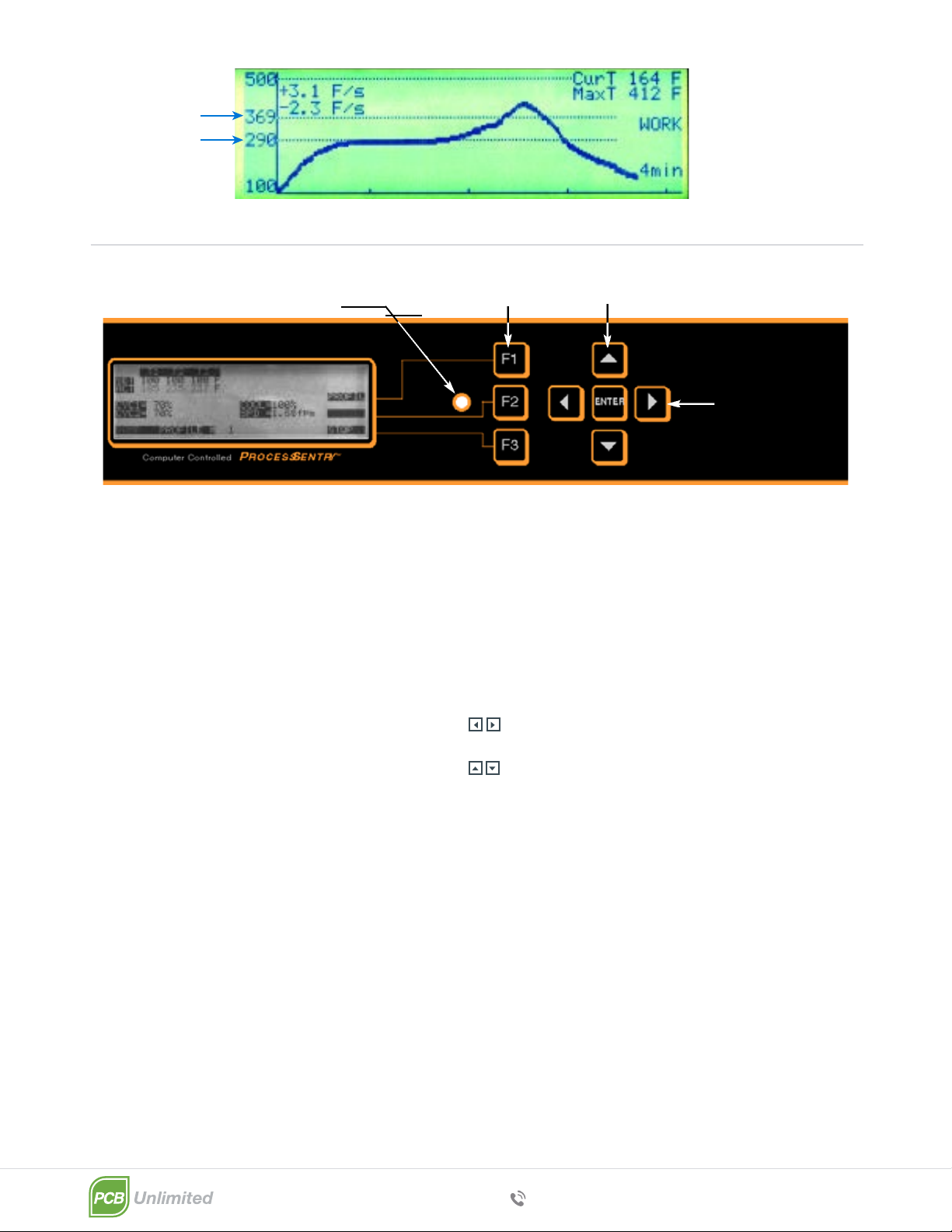
3. To display the graphic display on the screen press F1. The screen then shows the
profile curve in real me (beeps every second and makes a mark on the curve). It
also displays current temperature, maximum temperature, maximum heat ramp
rate and the maximum cooling ramp rate. The curve starts automacally when the
temperature probe reaches 100°F (37°C).
4. Press F1 (PROFILE) to deacvate profile probe and return to WORK display.
5. To stop machine, press F3 (alarm sounds, LED lights to warn that machine is off
and conveyor connues to run), press F3 again to turn LED and conveyor off.
6. To make “on-the-fly” changes in parameters while machine is running:
a. Press F2 (ADJUST) and ENTER key simultaneously (code to enter
on-the-fly
adjustments). The last parameter change made will be highlighted.
b. Scroll to appropriate field using le and right arrows ( )
c. Use scroll up, scroll down arrows ( ) to change seng of each
parameter.
d. When on-the-fly adjustments are complete press F2 and ENTER again
simultaneously to re-enter normal WORK mode.
7. Auxiliary external output: a DC output signal is provided on the main control
b o a rd at pin #8. This signal may be used to power a solid state relay which can
turn on or off any external device such as a computer, a printer, exhaust fans,
input or output conveyors etc. To toggle the signal on, press the le and right
arrows ( ) simultaneously. “EXT” will appear on the top of the display
toward the right side. To toggle the signal off, press the le and right arrows
( ). “EXT” will disappear from the display.
E. PROFILE Mode: Operator can change sengs of all displayed parameters.
1. Scroll le, scroll right arrows ( ) move the cursor through the profile fields
(Item flashing is ready to be changed)
2. Scroll up, scroll down arrows ( ) change seng of each parameter
3. PROF- (Fig. 3) For changing graphic profile display sengs including: Time in
minutes (choice of 4 or 8 min.), Maximum Temp (choice of 500°F/260°C or
700°F/371°C)., Temp 1 (arbitrary horizontal re ference line normally set for
acvaon temp e r a t u re), & Temp 2 (arbitrary horizontal re f e rence line nor
mally set for melng temperature) .
4. CYC - For changing cyclonic generator sengs from 20% to 100% in 10%
increments. To turn cyclonics off, set to 0%
5. COOL - For changing cooling staon sengs from 20% to 100% in 10%
increments. To turn cooling staon off, set to 0%
6. SPD - Sets conveyor speed in feet per minute or meters per minute
F. LOG Mode: Displays history of machine - date, me, profile no., and event which
occurred. Two pages of informaon are stored. Press F1 (SCRL) to toggle between
pages. When both pages are full, any new entry automacally erases the oldest entry.
G. TUNE Mode: DO NOT CHANGE (factory set).
(800) 348 9250
pcbunlimited.com [email protected]om
Fig. 2
Graphic profile display
Temp 2
Temp 1
So Keys
Interrupt LED
Le & right arrows
scroll cursor
through fields
Scroll up & Scroll down arrows
change seng of each par parameter
Fig. 3
h. CYCS - Shows number of cyclonic generators in machine
i . COOL - Jacket and/or control panel cooling fans stay on for indicated
me of up to 60 minutes (in 10 minute increments) aer shutdown.
j. CONVEYOR - DO NOT CHANGE (factory set)
k. CALIB - Disables internal thermocouple calibraon offset
l. Change Date and Time (at boom of screen)

(800) 348 9250
pcbunlimited.com [email protected]om
H. STATUS LIGHT TOWER (opon) - When main power is switched on, the light
tower executes a test sequence. The red, amber and green lights will light momentarily
in sequence. When in WORK mode, the amber light indicates that machine is ramping
but parameters are not within setpoint range. When parameters are with in range, the
amber light turns off and the green light is acvated. When any fault occurs or when
WORK mode is stopped, the red light acvates.
I. ENHANCED PRINTING OPTION:
Aserial printer or PC may be connected to the DB-25 connector located on the le
end of the control panel near the fan grille. With a PC, launch Microso Hyperterminal
and set up the parameters below. With a serial printer set parameters, below:
FUNCTIONS ARE AS FOLLOWS:
1. To print a profile from one of the stored menus: in profile mode, press F2.
2. To print the event log: in LOG mode, press F2
NOTE: Whenever a log event occurs while machine is in WORK or TUNE mode, the
event will automacally print.
3. To collect SPC data:
In WORK mode, press F2, le ( ) and up ( ) arrow simultaneously to print instantaneous
list of all actual parameters.
4. To print a profile graph:
In WORK mode, press F1 to enter graph screen. The profile will automacally be prin-
ted in real me.
J. PC INTERFACE OPTION
Follow instrucons provided in PC interface manual
BAUD:
DATABITS:
STOP BITS:
PARITY:
FLOW CONTROL:
4800 bps
8
1
NONE
NONE
5. Shutdown
CAUTION!
Failure to follow proper shutdown procedures may result in machine damage, fire or personal
injury!
A. Clear all product from machine conveyor.
B. To stop machine, press F3 (alarm sounds, LED lights to warn that machine is off,
conveyor connues to run), press F3 again to turn LED and conveyor off.
C. For auto-mer, refer to the SET-UP MODE secon of these instrucons. This
should be pre-programmed in SET UP mode; Press F3 to enter WORK mode.
Press F2 to enable automac start mer. Next start/stop me is displayed above
current me.

(800) 348 9250
pcbunlimited.com [email protected]om
CAUTION!
DO NOT TURN MAIN POWER SWITCH OFF, AS THIS WILL DEFEAT THE CHAMBER COO-
LING FAN TIMER, and thus prevent the machine from cooling itself sufficiently prior to full
shutdown.
Aer the chamber cooling fan mer has expired, the main MAIN POWER switch may be turned
off, providing automac mer is not being ulized. Computer is provided with baery for real
me clock. If me and date are not correct on inial start-up, baery must be replaced.
6. Maintenance
7. Inert Gas Opon
CAUTION!
NEVER CLEAN OR PERFORM MAINTENANCE ON THIS MACHINE WHILE IT IS HOT OR
CONNECTED TO ELECTRICAL POWER.
A. Check that the machine has fully cooled to room temperature and disconnect elec-
trical power at the circuit breaker. All switches should be turned off.
B Machine exterior panels may be cleaned periodically with a household type glass
cleaner or mild detergent using a clean so cloth. Viewing windows (parally
exterior polycarbonate), should be cleaned with a non-abrasive, so, lint-free cloth, as it
is suscepble to scratching.
C. Upper heang zones may be cleaned by using the hood to gain access. The upper
emiers and chamber surfaces tend to accumulate deposits caused by vaporized flux and
fumes, resulng in decreased efficiency of emiers and reflecve surfaces.
D. Lower heang zones may be accessed by gently liing the conveyor belt. The lower
zones tend to accumulate fallen dust and debris.
IMPORTANT!
Be careful when performing cleaning or maintenance funcons near the emiers, as
they are fragile and suscepble to breakage.
E. Apply a light coat of high temperature furnace lubricant (non-silicone based), to the
upper surfaces of the brass conveyor support guides as necessary. Conveyor squeaking
or scratching sounds indicate an absence of sufficient lubricaon.
F. Bearings used in your machine are pre-lubricated and sealed, thus requiring no regular
maintenance.
G. Prior to each start-up, make a thorough visual inspecon of the enre machine, and
repair or replace any worn or defecve parts. fumes, resulng in decreased efficiency
of emiers and reflecve surfaces.
D. Lower heang zones may be accessed by gently liing the conveyor belt. The lower
zones tend to accumulate fallen dust and debris.
1. Connect room temperature nitrogen to fing at rear of flow meter.
2. Turn flow meter knob counter-clockwise unl the floang steel ball in the meter indicates
the desired nitrogen volume. (300 SCFH is a recommended starng point).
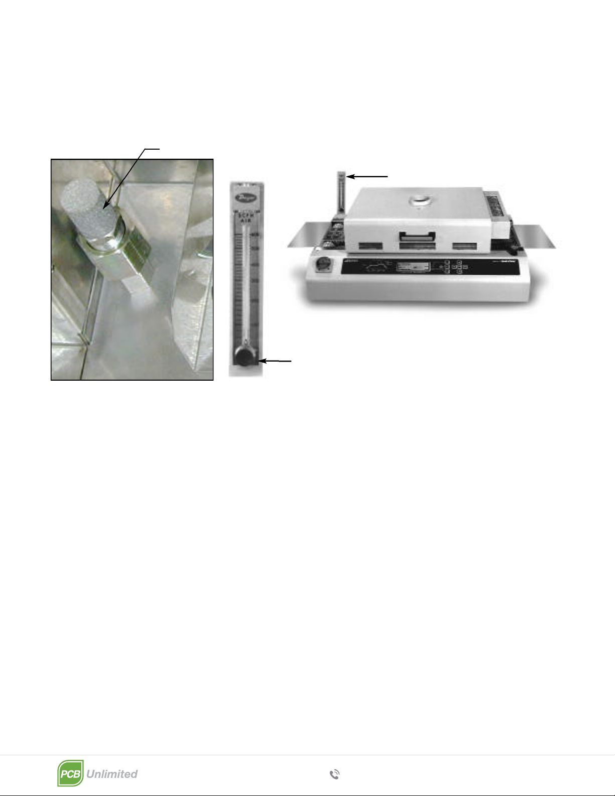
3. To decrease the O2 PPM level, increase the nitrogen volume. To increase the O2 PPM level,
decrease the nitrogen volume.
4. The oven must be purged with nitrogen for a minimum of 10 minutes prior to soldering.
5. IMPORTANT: When soldering is completed, it is important to turn off flow meter in order to
stop the flow of nitrogen.
(800) 348 9250
pcbunlimited.com [email protected]om
N2suffuser
Flow meter knob
Flow meter
This manual suits for next models
1
Table of contents
Popular Convection Oven manuals by other brands


Blodgett
Blodgett SC-10E Installation operating and maintenance istructions

IKEA
IKEA IBS324PSW00 Use & care guide

Insignia
Insignia NS-RGFCES2 user guide

Garland
Garland BCO-G-10 Installation & operation manual

Redneck Scientific
Redneck Scientific RCO Standard user manual

GE
GE Monogram ZET1038 owner's manual


