DDS Vector 530 User manual

Vector530UserManualVer122.doc - 1 - June 14, 2005
USER MANUAL
VECTOR 530 GPRS
Version 1.2

Vector530UserManualVer122.doc - 2 - June 14, 2005
TABLE OF CONTENTS
REVISION HISTORY ..................................................................................................................3
1Introduction .............................................................................................................................4
2Product Features .....................................................................................................................4
2.1 Technical Specifications................................................................................................................................4
2.2 Device Layout................................................................................................................................................6
2.3 Power Supply.................................................................................................................................................8
2.4 Chassis Ground..............................................................................................................................................8
3GPRS/GSM Modem Features................................................................................................9
3.1 RF Functionality ..........................................................................................................................................10
3.2 SIM Interface...............................................................................................................................................10
3.3 RF Interface .................................................................................................................................................11
3.4 RF Connections ...........................................................................................................................................11
3.5 RF Performance...........................................................................................................................................11
3.6 Antenna Specifications ................................................................................................................................12
APPENDIX A: SAFETY RECOMMENDATIONS (for information only) .....................13
APPENDIX B: INSTALLATION GUIDE ............................................................................15
APPENDIX C: TESTING THE GPRS MODEM ..................................................................17
Appendix D: FCC Part 15 Compliance Statement ..........................................................19
FCC Part 15.19 Compliance ....................................................................................................................................19
FCC Part 15.21 Compliance ....................................................................................................................................19
FCC Part 15.105 Compliance ..................................................................................................................................19
FCC RF Exposure Information................................................................................................................................19

Vector530UserManualVer122.doc - 3 - June 14, 2005
REVISION HISTORY
Version Date By Page No. Description
1 Dec 17, 2004 NG Initial release.
1.1 Mar 3, 2005 SD 11 Removed 5V SIM Card reference from
Section 3.2.
1.21 June 8, 2005 SD 12
19
Added to the antenna requirements.
Added Appendix D
1.22 June 13,2005 SD 12 Added to the antenna requirements

Vector530UserManualVer122.doc - 4 - June 14, 2005
1Introduction
This manual provides important operational and safety information for Vector 530 Mobile Data
Terminal(MDT) equipped with the North American GSM / GPRS 850/1900 MHz WaveCOM
Q2426B GPRS modem.
The Vector 530 is an affordable and easy to use Mobile Data Terminal (MDT) designed to meet
the needs of today’s dispatching and transport businesses using GPRS Public Data Networks as
its communications medium.
2Product Features
2.1 Technical Specifications
•Dimensions : 200mm (L) x 125mm (H) x 40mm (D)
•Weight : 700g approx
•Enclosure : Lightweight Injection molded plastic
•Processor : Intel 80C186, 20Mhz
•Memory : 512KB SDRAM, 512 KB Flash memory, 2KB EEPROM optional
32MB Flash disk for data storage.
•Display : 240 x 64 pixel graphical LCD for multi-language, multi-font support 4
LED’s for icon labels.
•Keyboard : Numeric keypad, 5 function keys, 4 cursor keys, power button.
•Audio : Integrated speaker with optional text-to-speech hardware support.
•GPS : Internal 8 channel GPS receiver with external antenna accuracy: < 6m
(50%), <9m (90%).
•Public data modem: WaveCOM Q2426B modem EGSM/GPRS 850/1900 MHz
version with 32Mb of flash memory and 4Mb of SRAM (32/4).
•Application Downloads: Over-the-air or Direct Serial connection.
•Integrated magnetic card reader: Single track on track 1 or track 2.

Vector530UserManualVer122.doc - 5 - June 14, 2005
•Interfaces: 4 RS-232C ports (2 internal, 2 external), 3 digital inputs/ 3 digital outputs.
•Options: SmartCAM (In-Vehicle Surveillance), Smartprint (Mobile Printer),
SmartPay (In-vehicle debit / Smart Card support).
•Electrical Requirements: Input Voltage: 13.8 VDC (10-17 VDC range), Current: Less
than 600 mA at 12VDC.
•Environmental : Operating Temperature : -20 deg C to + 70 deg C
•Storage Temperature : -40 deg C to + 80 deg C
•Relative Humidity : 5% to 80% (non- condensing)

Vector530UserManualVer122.doc - 6 - June 14, 2005
2.2 Device Layout
Vector 530 Front Panel Layout
Func Key (–)
Directional Pad (←↑→↓)
Programmable Function Keys (F1-F5)
Transmit LED
No ACK LED
GPS LED
Coverage LED
Send Key (
↵
)
Number Pad (0 – 9)

Vector530UserManualVer122.doc - 7 - June 14, 2005
Rear View
GPS Antenna connector
Mounting Threads
GPRS Modem Antenna Connector DB15 connector
Main DB25 connector
(Power Supply)

Vector530UserManualVer122.doc - 8 - June 14, 2005
Top View
Credit Card Swipe
2.3 Power Supply
Then unit is designed to operate normally from +10V up to +18V DC power source or car
battery. The nominal input voltage is 13.8V
2.4 Chassis Ground
The vehicle chassis ground (negative terminal of battery) is the recommended grounding point for vehicle
installation. There should be no residue to prevent proper grounding to the battery.

Vector530UserManualVer122.doc - 9 - June 14, 2005
3GPRS/GSM Modem Features
The Vector 530 GPRS-NA achieves high speed wireless connectivity by integrating the
WaveCOM WISMO QUIK series Q2426B GPRS modem.
Please note
the Q2426B modem features outlined in this section are as per the details supplied by
the WaveCOM, the modem module manufacturer.
•Size: 58.4x32.2x3.9mm
•2 Watts E-GSM 900/GSM 850 radio section running under 3.6 Volt.
•1 Watt GSM 1800/1900 radio section running under 3.5 Volts.
•Digital section running under 2.8 Volts.
•3V only SIM interface (for 5V SIM interface with external adaptation).
•Real Time Clock with Calendar.
•Battery Charge management.
•Echo Cancellation + noise reduction.
•Full GSM or GSM/GPRS software stack.
•Hardware GPRS Class 10 capable.
•Complete shielding
•Complete interfacing through a 60-pin connector:
-Power supply
-Serial Link
-Audio
-SIM card interface
-Keyboard
-LCD (not available with AT commands)
The WaveCOM Wismo Quik Q2426B has 2 external connections:

Vector530UserManualVer122.doc - 10 - June 14, 2005
•RF connection pads (to the antenna)
•60-pin General Purpose Connector (GPC) to Digital, Keyboard, Audio and Supply.
3.1 RF Functionality
The Radio Frequency (RF) interface complies with GSM 850 / PCS 1900 recommendation.
•Rx (GSM 850) : 869 to 894 MHz
•Rx (PCS 1900) :1930 to 1990 MHz
•Tx (GSM 850) : 824 to 849 MHz
•Tx( PCS 1900) : 1850 to 1910 MHz.
The Radio Frequency (RF) part is based on a specific dual band chip including:
•Low-IF Receiver
•Dual RF Synthesizer
•Digital IF to baseband Converter
•Offset PLL Transmitter
•(logarithmic) Power Amplifier controller
•Dual band power amplifier module
3.2 SIM Interface
The SIM interface is fully compliant with GSM11.11 recommendations regarding the SIM
functions.
Five signals are available from the SIM interface:-
SIM_VCC: SIM power supply-Pin 9.
SIM_RST: SIM reset-Pin 5.
SIM_CLK: SIM Clock-Pin 3.
SIM_DATA: I/O port- Pin 7.

Vector530UserManualVer122.doc - 11 - June 14, 2005
SIM _PRES: SIM card detect-Pin 50.
3.3 RF Interface
The impedance is 50 Ohms nominal and the DC impedance is 0 Ohm.
3.4 RF Connections
There are two possible ways to connect an antenna to the module:
•The antenna can be directly connected to the module on the “Antenna pad” by using a
spring contact.
•The antenna can be connected to the module through a coaxial cable. The coaxial
cable is connected to both the “Round pad” and the “Ground pad”.
3.5 RF Performance
RF performance is compliant with the recommendation GSM 05.05.
The main parameters for the Receiver are:
GSM850 Reference Sensitivity = -104dBm Static and TU High.
PCS1900 Reference Sensitivity = -102dBm Static and TU High.
Selectivity @ 200kHz: > +9dBc
Selectivity @ 400kHz: > +41dBc
Linear Dynamic Range: 63dB
Co-Channel Rejection: >=9 dBc.
And for the Transmitter:
Maximum Output power (GSM850) : 33dBm +/- 2dB at ambient temperature.
Maximum Output power (PCS1900) : 30dBm +/- 2dB at ambient temperature.
Minimum Output power (GSM850) : 5dBm +/- 5dB at ambient temperature.
Minimum Output power (PCS1900) : 0dBm +/- 5dB at ambient temperature.

Vector530UserManualVer122.doc - 12 - June 14, 2005
3.6 Antenna Specifications
The antenna must fulfill the following requirements:
A dual band patch antenna shall work in these frequency bands and have the
following characteristics:
•a minimum cable lead length of 3 meters
•Impedance: 50 Ohms
•VSWR Rx MAX =1.5: 1
•VSWR Tx MAX = 1.5:1
•Typical radiated gain: 0dBi on azimuth plane
•Frequency Tx : 824 to 849 MHz(GSM850) and 1850 to 1910 MHz(
PCS1900)
•Frequency Rx : 869 to 894 MHz(GSM850) and 1930 to 1990 MHz(
PCS1900)
•a threaded SMA Plug Connector. See Figure 3-1 below.
Figure 3-1. SMA Plug

Vector530UserManualVer122.doc - 13 - June 14, 2005
APPENDIX A: SAFETY RECOMMENDATIONS (for information only)
IMPORTANT: For the efficient and safe operation of this unit, please read this
information carefully.
This unit makes use of GSM/GPRS standard for cellular technology. There has been some
concerns about possible health effects of using GSM terminals. Although research on health
effects form RF energy has focused on the current RF technology for many years, scientists have
begun research regarding newer radio technologies such as GSM/GPRS.
After the existing research had been reviewed and after compliance to all applicable safety
standards had been tested, it has been concluded that the product was fitted for use.
If you are concerned about exposure to RF energy there are things you can do to avoid the
exposure by operating your terminal efficiently by following the below guidelines.
a) Efficient Terminal Operation: Operate the unit with the antenna fully extended and do
not hold /cover or obstruct the antenna when the unit is in use. Holding the antenna
affects the call quality and may cause the modem to operate at a higher power level than
needed.
b) Aircraft: Do not attempt to power up the unit on the aircraft. To prevent possible
interference with aircraft systems, Federal Aviation Administration (FAA) regulations
prohibit using the modem in any way while airborne.
c) Children: Do not allow children to play with the terminal. It is not a toy. Children could
hurt themselves while –playing with the antenna for example or damage the modem.
d) Blasting areas: To avoid interfering with blasting operations, turn your unit OFF when
in a <<blasting area>> or in areas posted: <<turn off two way radio>>. Construction crew
often use remote control RF devices to set off explosives.
e) Potentially explosive atmosphere: Turn your terminal OFF when in any area with a
potentially explosive atmosphere. It is rare, but your modem or its accessories could
generate sparks. Sparks in such areas could cause an explosion or fire resulting in bodily
injuries or even death.
Areas with a potentially explosive atmosphere are often, but not always, clearly marked.
They include fuelling areas such as petrol stations; below decks on boats; fuel or
chemical transfer or storage facilities; and areas where the air contains chemicals or
particles, such as grain, dust, or metal powders.

Vector530UserManualVer122.doc - 14 - June 14, 2005
Do not transport or store flammable gas, liquid, or explosives, in the compartment of
your vehicle which contains your terminal or accessories.
Before using your terminal in a vehicle powered by liquefied petroleum gas (such as
propane or butane) ensure that the vehicle complies with the relevant fire and safety
regulations of the country in which the vehicle is to be used.
f) Changes or modifications: Do not make changes or modifications to this unit without
the expressed written consent of the manufacturer.

Vector530UserManualVer122.doc - 15 - June 14, 2005
APPENDIX B: INSTALLATION GUIDE
CABLE INSTALLATION AND MOUNTING THE MDT IN THE VEHICLE
1. Install the Radio Pigtail per the Wiring Interface Instructions for that specific model
radio. (no radio associated with PDN Module Equipped Vector 530’s)
2. Install the MDT mount into the vehicle.
CAUTION: DO NOT DRILL OR SCREW INTO
EXISTING VEHICLE WIRING.
3. Route the Power leads from the Cable assembly through the firewall of the vehicle and
near the battery contacts. If drilling a new hole through the firewall be sure and install a
rubber grommet so the sheet metal will not cut through the cable. When routing the wire
under the hood make sure the cable is not near the exhaust manifold where it may become
burnt and away from the distributor and computer module where it may pick up noise
interference.
4. Cut the Power lead to the proper length so that it reaches the battery contacts as well as a
ground.
5. Connect a Fuse holder to the Red and Black wires in the power lead. One fuse holder for
both wires. Connect a terminal connector to the other wire of the fuse holder and connect to
the Battery + terminal. This should be connected directly to the battery to prevent noise
interference.
6. Connect a terminal connector to the White and Green wires of the Power lead and secure
to the grounding post on the fender.
7. Tie wrap the power lead so that there will not be strain on the terminal connectors and so
the wire is secure and will not rub on hot engine parts.
8. Connect P4 (DB15) of the wiring harness to the DB15 of the Radio. Tighten the screws
finger tight.
9. A hidden emergency switch may be installed by connecting the Green wire of the meter
DB9 pigtail to a normally closed switch, and then connecting the other end of the switch to
the White wire of the meter pigtail. IF THE EMERGENCY SWITCH IS NOT BEING
USED MAKE SURE THE GREEN AND WHITE WIRES OF THE METER PIGTAIL
ARE CONNECTED TOGHETHER.

Vector530UserManualVer122.doc - 16 - June 14, 2005
10. Connect P5 (DB9) of the wiring harness to the meter pigtail.
11. On the meter pigtail join the Green, White and Red wires together and insulate the wires.
12. Connect P2 (DB9) to the smart meter DB9.
13. Connect P1 DB25 connector to the back of the MDT. DO NOT over tighten the set
screws.
14. Connect the MDT to the mount.
15. Tie wrap any loose cabling up under the dash so that the driver or passengers will not
step on it and cause unnecessary strain.
16. Perform Set Up and Tuning procedures if they have not yet been performed.
METER INTERFACE
1. Connect the Green, White and Red wires of the meter pigtail together and insulate the
wires.
2. Connect the meter pigtail to P5 of the wiring harness.
3. The BLACK wire is the meter status wire.
4. Connect P2 of the wiring harness to the DB9 serial port of the Smart meter.
ONLY if a Smart Meter is used.
GPS ANTENNA MOUNTING AND CABLE ROUTING
1. A suggested mounting place for the GPS antenna is under the top kight light.
2. Ensure the top light is not coated with a metallic paint/coloring.
3. Ensure the top of the Antenna is not obstructed by metal, and is not too close to the bulbs.
4. The cable can then be run through the same hole as the existing wires
5. Ensure the cable is not pinched or cut in any way, and is threaded down the passenger
side of the window pillar.
6. It is suggested the GPS antenna should not be too close to the GPRS antenna.

Vector530UserManualVer122.doc - 17 - June 14, 2005
APPENDIX C: TESTING THE GPRS MODEM
1. Connect the GPRS antenna to the SMA connector plug provided at the back
of the Vector 530 unit.2
2. Connect the Vector to a Windows PC using a serial cable.
3. Bring up Windows HyperTerminal on a PC to interact with the GPRS
modem module.
Hyperterminal Session Settings:
•COM Port Configuration of “9600 baud, 8, n, 1, none”
•Settings | ASCII Setup of:
oSend line ends with line feeds
oEcho typed characters locally
oAppend line feeds to incoming line ends
oWrap lines that exceed terminal width
Figure 1a. HyperTerm COM Settings Figure 1b. HyperTerm ASCII Terminal Settings
4. Power Up the unit and carry out the following AT commands to test the
functionality of the GPRS modem

Vector530UserManualVer122.doc - 18 - June 14, 2005
•ATD1234 ; dial
•ATA ; call answered
•AT+CFUN=1 ; or other means to detach then reattach the
; unit from/to the network
•AT+CPIN="1234" ; to enter a PIN
•AT+CREG=1 ; to monitor registration

Vector530UserManualVer122.doc - 19 - June 14, 2005
Appendix D: FCC Part 15 Compliance Statement
FCC Part 15.19 Compliance
This device complies with Part 15 of the FCC Rules. Operation is subject to the
following two conditions: (1) this device may not cause harmful interference, and
(2) this device must accept any interference received, including interference that
may cause undesired operation.
FCC Part 15.21 Compliance
Modifications not expressly approved by Digital Dispatch void the user's authority to operate the
equipment.
FCC Part 15.105 Compliance
NOTE: This equipment has been tested and found to comply with the limits for a Class B digital
device, pursuant to Part 15 of the FCC Rules. These limits are designed to provide reasonable
protection against harmful interference in a residential installation. This equipment generates,
uses and can radiate radio frequency energy and, if not installed and used in accordance with the
instructions, may cause harmful interference to radio communications. However, there is no
guarantee that interference will not occur in a particular installation. If this equipment does
cause harmful interference to radio or television reception, which can be determined by turning
the equipment off and on, the user is encouraged to try to correct the interference by one or more
of the following measures:
•Reorient or relocate the receiving antenna.
•Increase the separation between the equipment and receiver.
•Connect the equipment into an outlet on a circuit different from that to which the
receiver is connected.
•Consult the dealer or an experienced radio/TV technician for help.
FCC RF Exposure Information
The mounting of this device and antenna must be done by professional installers to ensure that
the user or nearby persons will maintain at least 20 cm from the antenna in normal use.
Table of contents
Other DDS Touch Terminal manuals
Popular Touch Terminal manuals by other brands

Avaya
Avaya Definity 6408 user manual
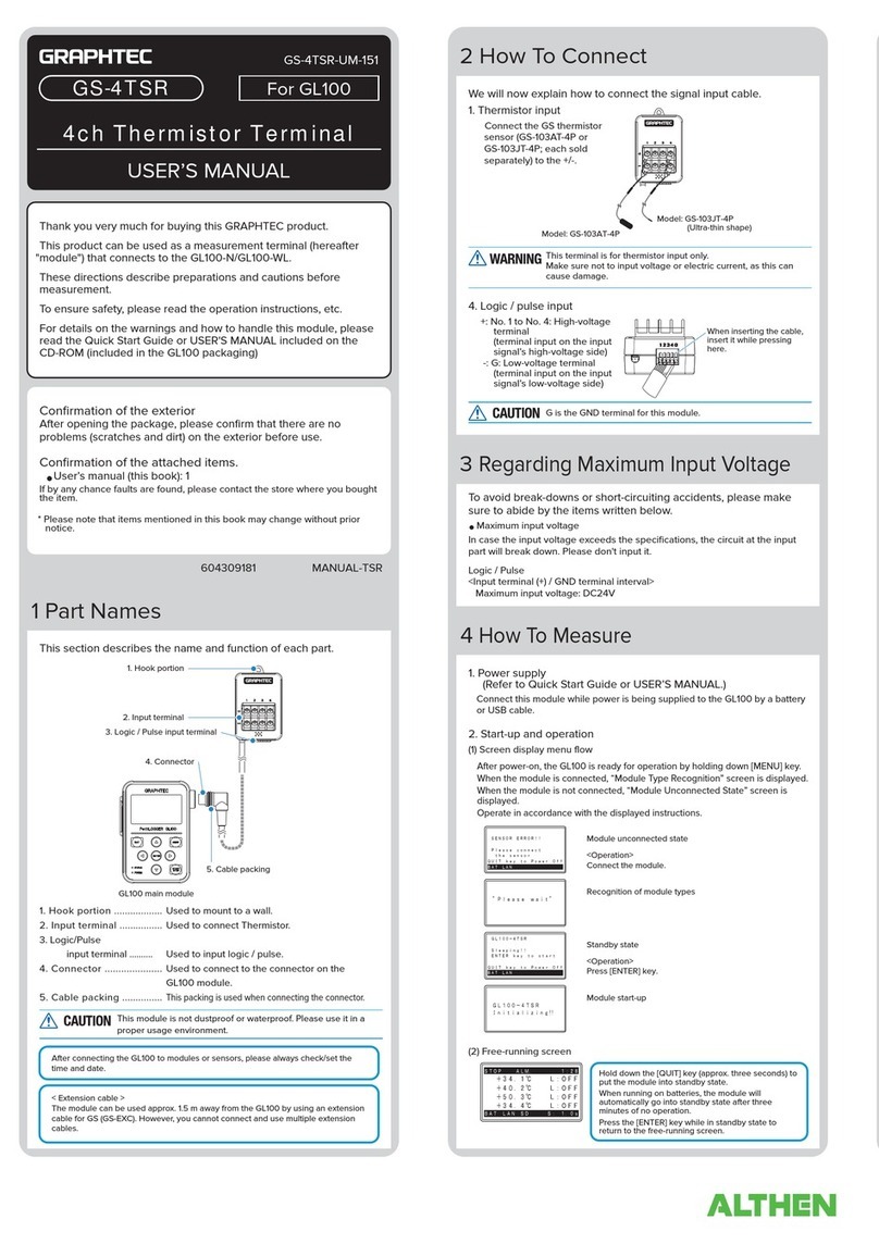
GRAPHTEC
GRAPHTEC GS-4TSR user manual
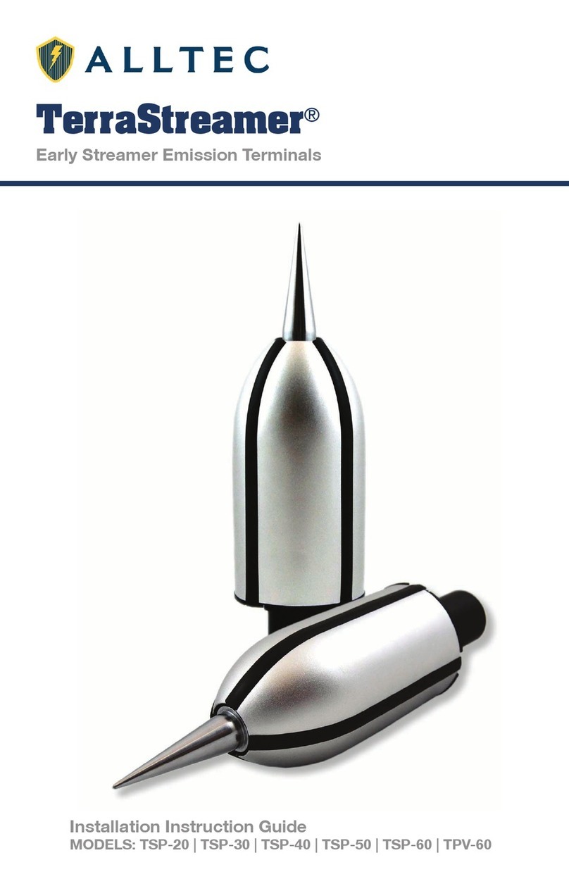
ALLTEC
ALLTEC TerraStreamer TSP-20 Installation instruction guide

Thrane&Thrane
Thrane&Thrane Explorer 727 user manual

VeriFone
VeriFone V400 Series Operational Procedures Guide

Elo TouchSystems
Elo TouchSystems 17" B?Series Rev?B All?in?One Touchcomputer user manual

