De Coninck Stoptronic User manual

© 2005 De Coninck Trafc Management BV. All rights reserved.
UK
1
Contents
1. INTRODUCTION 2
2. OBJECTIVES 3
3. ASSEMBLY 4
4. PREPARATION 6
5. GENERAL INFORMATION 7
6. STOPTRONIC USE 7
6.1 Common manoeuvres 7
6.2 Braking deceleration 8
6.3 Braking distance and stopping distance 9
7. BRAKING 10
7.1 Emergency stop 11
7.2 Braking distance formula 11
7.3 Emergency stop (dry road surface) 12
7.4 Emergency stop (wet road surface) 13
8. NOTES 14

© 2005 De Coninck Trafc Management BV. All rights reserved.2
UK
1. IntRoDUCtIon
The STOPTRONIC® provides insight into the acceleration,
deceleration, braking and stopping of a vehicle and this has a
positive inuence on the driving behaviour. Through the use of the
STOPTRONIC®, the driver is able to better anticipate trafc situations
which, in turn, improves road safety.
The STOPTRONIC® not only improves trafc safety. By avoiding
unnecessary acceleration and deceleration, the fuel consumption is
greatly decreased, which is not only benecial to the environment, but
also saves the driver a great deal of money.

© 2005 De Coninck Trafc Management BV. All rights reserved.
UK
3
2. oBJeCtIVes
The STOPTRONIC® has been developed to give drivers insight into
the dynamics of acceleration and braking deceleration, as well as
braking and stopping distances.
The STOPTRONIC® helps drivers to develop a good feeling for
braking by displaying a veriable representation of the braking
behaviour.
With the aid of the STOPTRONIC®, the driver will:
Improve his/her road observation and start to look further ahead.
Learn to brake appropriately and more safely.
Learn to estimate the stopping distance of his/her vehicle.
Learn to estimate the speed of other vehicles.
Keep a safe distance from the car in front.
Be able to make a safe emergency stop.
Learn to use the clutch, gears and accelerator pedal more smoothly.
Change gear at the right time, which prevents high fuel consumption
and (unnecessary) wear to the vehicle.
■
■
■
■
■
■
■
■
© 2005 De Coninck Trafc Management BV. All rights reserved.
4
UK
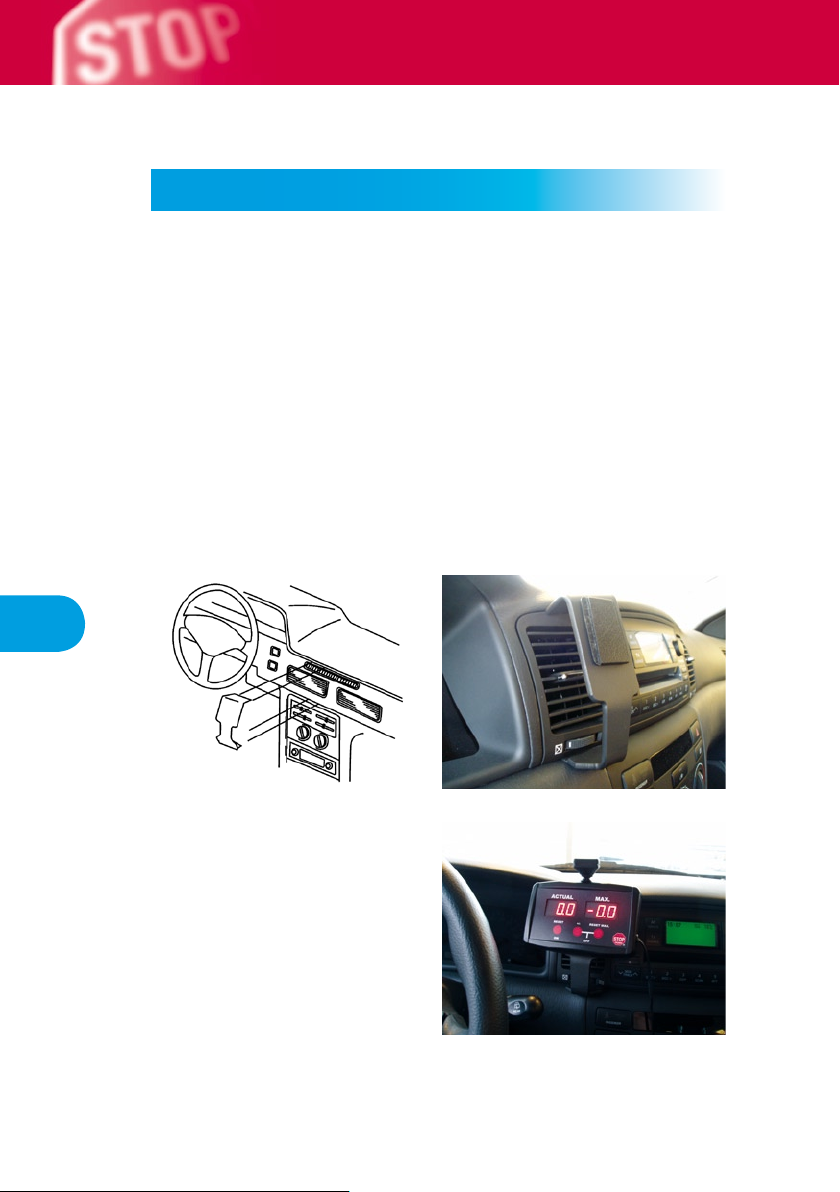
3. AsseMBLY
The STOPTRONIC® can be easily tted to the Brodit ProClip using the
MoveClip provided (see the diagram below).
Return the completed voucher and receive the assembly bracket
specic to your vehicle.
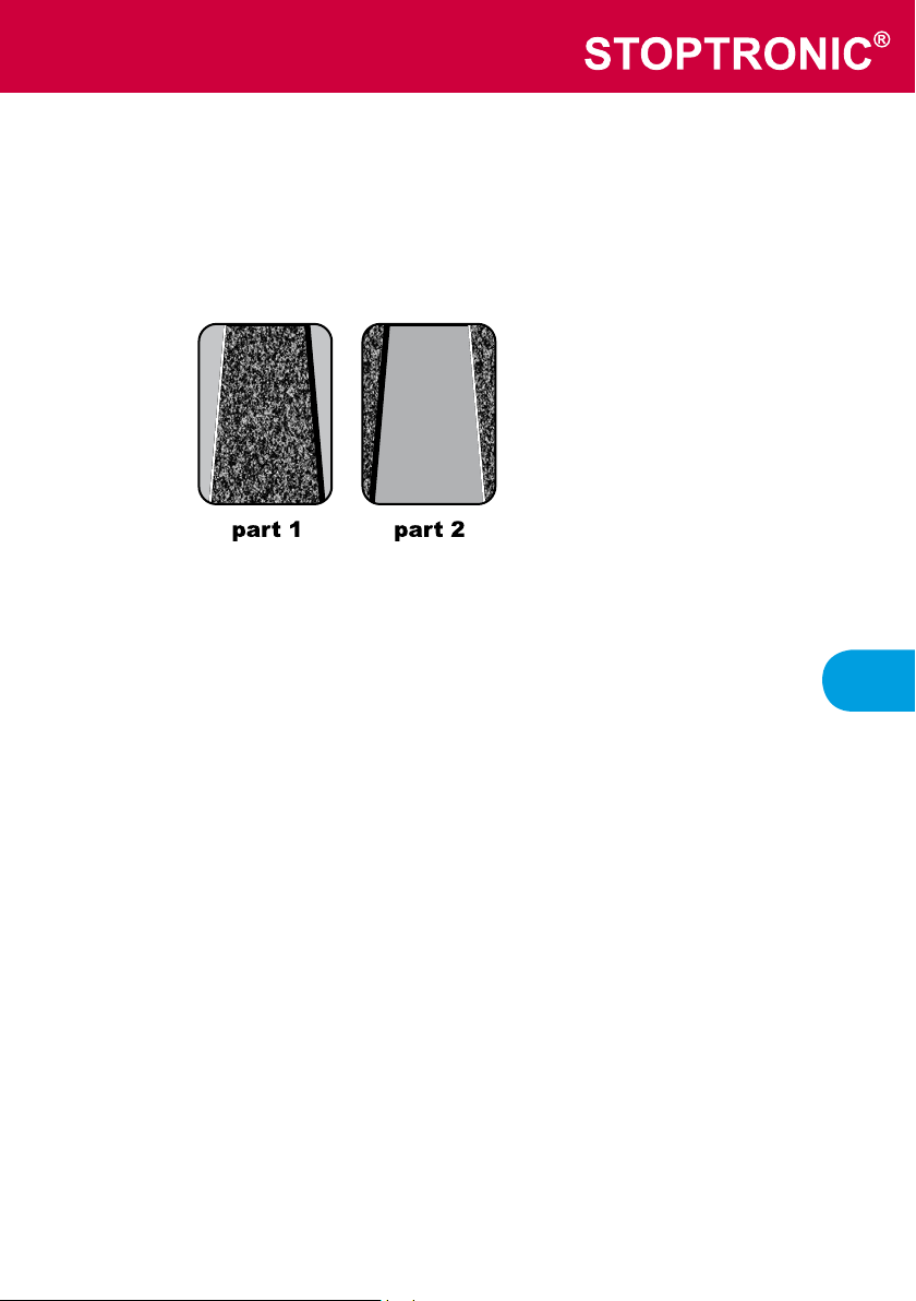
Use the cloth provided to remove any grease from the areas on
the rear of the STOPTRONIC® and the ProClip and wait until these
areas are dry. Remove the protective strips from the MoveClip (which
consists of two parts) and press them rmly into place on both the
STOPTRONIC® and the ProClip.
© 2005 De Coninck Trafc Management BV. All rights reserved.
UK
5
note!
The MoveClip is conical. Therefore, stick part 1 to the ProClip and part
2 to the rear of the STOPTRONIC®, as shown below.
!

© 2005 De Coninck Trafc Management BV. All rights reserved.6
UK
4. PRePARAtIon
Use the spirit level provided to level the recording sensor (X) and point
it in the driving direction.
Next, connect the STOPTRONIC® to the cigarette lighter. The
STOPTRONIC® can also be connected directly to the 12 V cabling. If
the STOPTRONIC® is connected to the 12 V cabling, make sure it is
turned on via the ignition to prevent it from always being turned on.
The button (1) must be pressed briey to zero the displays.
The STOPTRONIC® is now ready for use.

© 2005 De Coninck Trafc Management BV. All rights reserved.
UK
7
5. GeneRAL InFoRMAtIon
The STOPTRONIC® has two displays. The left-hand display shows
the current acceleration and deceleration and the right-hand display
shows the highest measured value.
By briey pressing button (2), the right-hand display will show the
acceleration or deceleration (-). If this button is kept pressed, the
lighting is dimmed.
Button (3) zeros the highest measured value.
The “Driving Procedure” must always be observed when pulling away,
decelerating, braking and stopping.
6. stoPtRonIC Use
6.1 Common manoeuvres
The following values must be assumed in order to drive as safely and
as economically as possible.
manoeuvre maximum STOPTRONIC® value
pulling away 2 m/s²
changing up gear 0 m/s²
braking within a built-up area -2 m/s²
braking outside a built-up area -4 m/s²

© 2005 De Coninck Trafc Management BV. All rights reserved.8
UK
6.2 Braking deceleration
The speed that the vehicle decreases per second when braking is
called the braking deceleration. The braking deceleration is expressed
in m/sec².
The minimum legal braking deceleration is not the same for every
vehicle. A number of examples from the Dutch vehicle regulations are
given below:
Passenger car: 5.2 m/sec².
Commercial car built before 1/1/1998: 4.0 m/sec².
Commercial vehicle built on or after 1/1/1998: 4.5 m/sec².
Coach: 4.5 m/sec².
Motorcycle built before 1/4/1998: 4.5 m/sec².
Motorcycle built on or after 1/4/1998: 5.2 m/sec² (with both brakes).
See the vehicle regulations applicable to your country for the minimum
legal braking deceleration.
In practice, assuming ideal conditions, such as a dry road surface,
good suspension, good tyres and good brakes, vehicles can achieve
a much higher braking deceleration than the minimum specied value.
Under these ideal circumstances, a braking deceleration of between 8
and 10 m/sec² can be achieved.
For lorries, this maximum value is between 6 and 8 m/sec², depending
on the type of braking system.
■
■
■
■
■

© 2005 De Coninck Trafc Management BV. All rights reserved.
UK
9
6.3 Braking distance and stopping distance
The stopping distance is the braking distance plus the distance
travelled during the reaction time.
An average reaction time of 1 second is usually assumed, although
scientic studies give the following statistics:
A reaction time of 0.4 sec. is achieved by 2% of drivers.
A reaction time of 0.83 sec. is achieved by 98% of drivers.
The reaction time consists of a physical reaction by the driver of 0.8
seconds (observation – recognizing danger – moving foot until the
braking action begins) and a time of 0.2 seconds for the braking
system to reach full pressure (differs for each braking system).
Due to the pneumatic braking system of lorries, the time it takes the
braking system to reach full pressure is usually slightly longer. As a
result, the stopping distance is also longer.
The braking distance for a motorcycle is, in principle, the same as that
for a passenger car. In the event of an emergency stop, though, there
is a chance that the front or rear wheel will lock and this can lead to a
fall.
■
■

© 2005 De Coninck Trafc Management BV. All rights reserved.10
UK
7. BRAKInG
Whilst braking, the driver must not change down gears, both hands
must be on the steering wheel and the clutch should not be operated.
The clutch pedal should only be operated just before coming to a
standstill to prevent the engine from stalling.
Whilst braking, the deceleration will slowly be increased to the
following values:
2 m/sec² - 4 m/sec² - 6 m/sec² - 8 m/sec².
By slowly releasing the brake before the vehicle comes to a complete
standstill, less force will be placed on the vehicle’s suspension and a
nal jolt will be avoided.
4

© 2005 De Coninck Trafc Management BV. All rights reserved.
UK
11
7.1 Emergency stop
A driver must be able to brake as described previously in “Braking”
before attempting an emergency stop.
During an emergency stop, the clutch pedal must be operated
simultaneously with the brake pedal. This will prevent the engine from
stalling and, as a result, the ABS and the power steering system will
also remain operational.
If the vehicle does not have ABS, then the vehicle must be braked
until just before the wheels lock. This is achieved by braking forcefully
and, once the wheels lock, slowly releasing the brakes until the
wheels start to roll again. This will produce the shortest braking
distance and the vehicle will remain steerable.
7.2 Braking distance formula
The braking distance (S) depends on the speed (V) and the
deceleration (A). The formula for calculating the braking distance is:
S = V² / 2 x A
The speed must be converted to m/sec. To do so, the speed in km/h
must be divided by 3.6. Example: 36 km/h divided by 3.6 is 10 m/sec.
The result (S) is the braking distance in metres.
A number of distances are given in the tables below.
4

© 2005 De Coninck Trafc Management BV. All rights reserved.12
UK
7.3 Emergency stop (dry road surface)
Emergency stop with a braking deceleration of -8 M/S²
speed braking
distance (m)
distance for
a reaction
time of 1 sec.
stopping
distance (m)
10 km/h = 2.78 m/s 0.48 m 2.78 m 3.26 m
30 km/h = 8.33 m/s 4.34 m 8.33 m 12.67 m
50 km/h = 13.89 m/s 12.06 m 13.89 m 25.95 m
70 km/h = 19.44 m/s 23.62 m 19.44 m 43.06 m
80 km/h = 22.22 m/s 30.86 m 22.22 m 53.08 m
90 km/h = 25 m/s 39.06 m 25 m 64.06 m
100 km/h = 27.78 m/s 48.23 m 27.78 m 76.01 m
120 km/h = 33.33 m/s 69.43 m 33.33 m 102.76 m
4

© 2005 De Coninck Trafc Management BV. All rights reserved.
UK
13
7.4 Emergency stop (wet road surface)
Emergency stop with a braking deceleration of -5 M/S²
speed braking
distance (m)
distance for
a reaction
time of 1 sec.
stopping
distance (m)
10 km/h = 2.78 m/s 0.77 m 2.78 m 3.55 m
30 km/h = 8.33 m/s 6.94 m 8.33 m 15.27 m
50 km/h = 13.89 m/s 19.92 m 13.89 m 33.81 m
70 km/h = 19.44 m/s 37.79 m 19.44 m 57.23 m
80 km/h = 22.22 m/s 49.37 m 22.22 m 71.59 m
90 km/h = 25 m/s 62.50 m 25 m 87.50 m
100 km/h = 27.78 m/s 77.17 m 27.78 m 104.95 m
120 km/h = 33.33 m/s 111.09 m 33.33 m 144.42 m
4

© 2005 De Coninck Trafc Management BV. All rights reserved.14
UK
8. notes

© 2005 De Coninck Trafc Management BV. All rights reserved.
UK
15

© 2005 De Coninck Trafc Management BV. All rights reserved.16
UK

Table of contents
Popular Automobile Accessories manuals by other brands


Strong Frontier
Strong Frontier TE800-T owner's manual

Reese Explore
Reese Explore 1390600 instructions

Directed
Directed 403.VW10 installation guide

Boss Audio Systems
Boss Audio Systems BV435WTR user manual

AMP Research
AMP Research BedStep 75310-01A quick start guide

Kuda-Phonebase
Kuda-Phonebase 3130 Installation instruction


