manuals.online logo
Brands
  1. Home
  2. •
  3. Brands
  4. •
  5. Roadmaster
  6. •
  7. Automobile Accessories
  8. •
  9. Roadmaster 2120 Quick start guide

Roadmaster 2120 Quick start guide

Read the instructions before installing
the kit components. Failure to understand
how to install this product could result in
property damage, personal injury or even
death.
Before you connect the wiring…
If the towing vehicle has ‘separate’ brake and turn sig-
nals (Figure 1), an optional Brite-Lite™3-to-2 converter
(part number 732) must be installed.
Connecting the wiring…
Follow the steps below to connect the included three-foot
wiring harness to the towing vehicle’s brake, turn signal
and taillight wires…
1. Use a test light to identify the left brake and turn signal
wire, right brake and turn signal wire, taillight wire and
ground wire on the towing vehicle’s electrical harness.
2. The wires on the three-foot harness are color-coded.
They must be attached to the towing vehicle’s wiring as
follows:
included
three-foot towing vehicle’s
wiring harness electrical harness
White............................................... Ground
Brown ............................................. Taillights
Yellow ........................................Left Brake/Turn
Green....................................... Right Brake/Turn
3. There are two slots at the sides of each of the included
splice connectors. The bottom slot is plugged on one end
and open on the other.
Insert the end of one of the wires on the three-foot
harness into the open end of the bottom slot on one of the
connectors, until it can go no farther. Look through the top
of the connector to make certain that the wire extends past
the metal band at the center of the connector.
Push the top of the connector over the appropriate
wire on the towed vehicle’s electrical harness, until the
wire snaps into the top slot.
Use pliers to fold the plastic tab on the connector over
the top, until the tab snaps into place. Cover the connector
with electrical tape.
Repeat for the other three wires.
Unless the wires are attached as described above,
the magnetic lights on the towed vehicle will not il-
luminate in tandem with the towing vehicle’s lights.
Drivers behind the towed vehicle will not be alerted
when the towing vehicle stops or turns, which may
cause an accident.
Failure to follow these instructions may cause prop-
erty damage, personal injury or even death.
4. Use one or more wire ties to secure the other end of
the three-foot wiring harness (with the female four-prong
continued on next page
Figure 1
IMPORTANT NOTICE!
Safety Definitions
Statements in these instructions identified as follows are of special significance.
WARNING indicates a potentially hazardous situ-
ation which, if not avoided, could result in property
damage, serious personal injury or even death.
CAUTION indicates a potentially hazardous situ-
ation which, if not avoided, may result in property
damage, or minor or moderate personal injury.
CAUTION used without the safety alert symbol
indicates a potentially hazardous situation which, if
not avoided, may result in property damage.
NOTE
Refers to important information and is placed in italic
type. It is recommended that you take special notice of
these items.
Installation and Use
Magnetic Tow Lights
part number 2120
All specifications are subject to change without notice.
other damage to the vehicle’s finish caused by im-
proper use of the magnetic tow lights are not covered
under warranty.
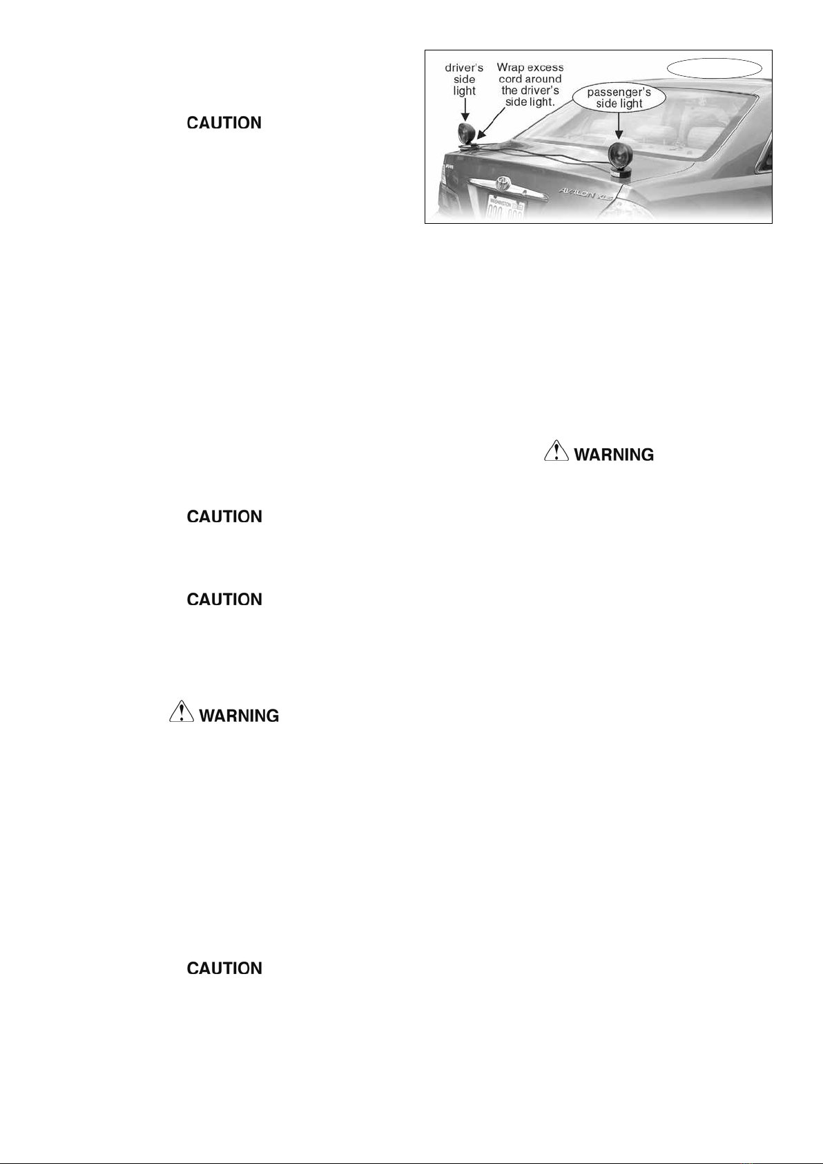
4. If there is excess electrical cord, wrap the slack around
the driver’s side light, as shown in Figure 2.
5. Position the two lights (Figure 2) over the points you
have chosen.
Note: the driver’s side light has two electrical cords
extending from the base; the passenger’s side light has
only one (Figure 2).
Position the driver’s side and passenger’s side
lights as described above, and as shown in Figure 2. If
the lights are reversed, the towed vehicle’s turn signals
will be reversed, which may cause an accident.
Failure to follow these instructions may cause prop-
erty damage, personal injury or even death.
6. Each time before towing, test the system for proper
function, as described in step five under “Connecting the
wiring.”
7. The weather cover over the female four-prong con-
nector at the towing vehicle will prevent damage from road
debris or corrosion. Keep the female four-prong connector
covered when not in use.
Figure 2
continued from preceding page
connector) at the back of the towing vehicle, close to the
center.
The four-prong connector must be attached at the
rear of the towing vehicle, close to the center. Attaching
the connector toward either side of the towing vehicle
may cause the wiring to be pulled loose, or to drag on
the ground, when the towing vehicle turns.
5. Test the system: follow the steps below to attach the
lights to the rear of the towed vehicle. With the towing
vehicle’s engine on (or the ignition key in the ‘on’ posi-
tion), turn on the headlights. Now, press and release the
brake pedal and activate the turn signals to verify that the
magnetic lights work in tandem with the towing vehicle’s
turn signals and brake lights.
Attaching the lights…
1. The magnetic tow lights are attached to a length of
electrical cord with a male four-prong connector. Plug
this connector into the female connector at the end of the
three-foot wiring harness.
2. Route the electrical cord and the magnetic lights to the
back of the towed vehicle.
Position the electrical cord so that it will not rub
against the towed vehicle’s finish. The finish may be
damaged if the cord rubs against it during towing.
Keep the cord away from all moving parts. Severe
damage to both vehicles, as well as the components
of the towing system and the magnetic lights, can oc-
cur if the cord becomes entangled in the wheels, the
tow bar or hitch, or any other moving component.
The wiring can be damaged if the electrical cord
is pinched or crushed. If the wiring is damaged, the
magnetic lights will not operate.
Damaged wiring may also cause a short circuit,
which can blow a fuse in the towing vehicle, as well
as cause other, consequential damage to the towing
vehicle’s electrical system or other components.
Failure to follow these instructions may cause prop-
erty damage, personal injury or even death.
3. Choose an area on the rear of the towed vehicle to
position the two magnetic lights, so that they will be clearly
visible to drivers behind the towed vehicle.
To reduce the likelihood of scratches or other dam-
age to the towed vehicle’s finish, make certain that
both the underside of the magnets and the surface of
the towed vehicle are clean.
Also, do not drag the magnets across the surface
of the towed vehicle.
Failure to follow these instructions will damage
the towed vehicle’s finish. Scratches, paint chips and
Learn more about other trailer hitches & towing products on our website.

Other Roadmaster Automobile Accessories manuals

Roadmaster 195125 User manual

Roadmaster

Roadmaster 195125 User manual

Roadmaster FuseMaster 76512 User manual

Roadmaster

Roadmaster FuseMaster 76512 User manual

Roadmaster Invisibrake 8700 User manual

Roadmaster

Roadmaster Invisibrake 8700 User manual

Roadmaster Falcon 2 Original instructions

Roadmaster

Roadmaster Falcon 2 Original instructions

Roadmaster 1109-174 User manual

Roadmaster

Roadmaster 1109-174 User manual

Roadmaster 9700 User manual

Roadmaster

Roadmaster 9700 User manual

Roadmaster 88336 User manual

Roadmaster

Roadmaster 88336 User manual

Roadmaster 156-75 User manual

Roadmaster

Roadmaster 156-75 User manual

Roadmaster 9300 Operating instructions

Roadmaster

Roadmaster 9300 Operating instructions

Roadmaster FALCON 522 Original instructions

Roadmaster

Roadmaster FALCON 522 Original instructions

Roadmaster Hands-Free Bluetooth Car Kit VRBT330W Owner's manual

Roadmaster

Roadmaster Hands-Free Bluetooth Car Kit VRBT330W Owner's manual

Roadmaster 031-5 User manual

Roadmaster

Roadmaster 031-5 User manual

Roadmaster BrakeMaster 9000 User manual

Roadmaster

Roadmaster BrakeMaster 9000 User manual

Roadmaster StowMaster ALL TERRAIN User manual

Roadmaster

Roadmaster StowMaster ALL TERRAIN User manual

Roadmaster FuseMaster 76511 User manual

Roadmaster

Roadmaster FuseMaster 76511 User manual

Roadmaster Even Brake 9400 User manual

Roadmaster

Roadmaster Even Brake 9400 User manual

Roadmaster 156-25 User manual

Roadmaster

Roadmaster 156-25 User manual

Roadmaster Blackhawk 2 All Terrain User manual

Roadmaster

Roadmaster Blackhawk 2 All Terrain User manual

Roadmaster 2000-1 User manual

Roadmaster

Roadmaster 2000-1 User manual

Roadmaster 155 User manual

Roadmaster

Roadmaster 155 User manual

Roadmaster Sterling All Terrain User manual

Roadmaster

Roadmaster Sterling All Terrain User manual

Roadmaster Tracker Original instructions

Roadmaster

Roadmaster Tracker Original instructions

Roadmaster Falcon 2 User manual

Roadmaster

Roadmaster Falcon 2 User manual

Roadmaster 1139-143 User manual

Roadmaster

Roadmaster 1139-143 User manual

Popular Automobile Accessories manuals by other brands

Magneti Marelli AC161 Installation instruction

Magneti Marelli

Magneti Marelli AC161 Installation instruction

FDI uEZ GUI Start here

FDI

FDI uEZ GUI Start here

JCROffroad JT Install instructions

JCROffroad

JCROffroad JT Install instructions

Rostra VOXXElectronics 250-1930 owner's guide

Rostra

Rostra VOXXElectronics 250-1930 owner's guide

TOP VEHICLE TECH GR3FORD5 installation manual

TOP VEHICLE TECH

TOP VEHICLE TECH GR3FORD5 installation manual

Safe Fleet PRIME DESIGN AR-2000-BLK manual

Safe Fleet

Safe Fleet PRIME DESIGN AR-2000-BLK manual

Skoda Fabia Combi 5J Fitting instructions

Skoda

Skoda Fabia Combi 5J Fitting instructions

Camcar 40077 Al Mounting instructions

Camcar

Camcar 40077 Al Mounting instructions

Camcar 40089 AL Mounting instructions

Camcar

Camcar 40089 AL Mounting instructions

Impac Tradesman 2000 installation manual

Impac

Impac Tradesman 2000 installation manual

DVB OFFROAD BRSB-01 installation manual

DVB

DVB OFFROAD BRSB-01 installation manual

Safari Snorkel SS385HF installation guide

Safari Snorkel

Safari Snorkel SS385HF installation guide

ULTIMATE SPEED 279746 Assembly and Safety Advice

ULTIMATE SPEED

ULTIMATE SPEED 279746 Assembly and Safety Advice

SSV Works DF-F65 manual

SSV Works

SSV Works DF-F65 manual

ULTIMATE SPEED CARBON Assembly and Safety Advice

ULTIMATE SPEED

ULTIMATE SPEED CARBON Assembly and Safety Advice

Witter F174 Fitting instructions

Witter

Witter F174 Fitting instructions

WeatherTech No-Drill installation instructions

WeatherTech

WeatherTech No-Drill installation instructions

TAUBENREUTHER 1-336050 Installation instruction

TAUBENREUTHER

TAUBENREUTHER 1-336050 Installation instruction

manuals.online logo
manuals.online logoBrands
  • About & Mission
  • Contact us
  • Privacy Policy
  • Terms and Conditions

Copyright 2025 Manuals.Online. All Rights Reserved.