De Havilland DASH8 100 Series User manual

**ON A/C ALL ENGINE FUEL INDICATING − GENERAL
1. General
Engine fuel indicating associated with the engine fuel and control system consists of a fuel
low pressure warning system, a fuel flow indicating system and a fuel temperature indicating
system for each engine. The systems for each engine have like components and are identical
in operation.
Fuel low pressure warning consists of a fuel low pressure switch, sensing fuel pump inlet
pressure and connected by electrical wiring to the caution lights system. Fuel flow indicating
is by means of a transmitter sensing fuel flow to the engine fuel manifold, connected by
electrical wiring to an indicator on the engine instrument panel. Fuel temperature indicating is
by means of a transmitter sensing temperature at the fuel pump inlet, connected by electrical
wiring to an indicator on the engine instrument panel.
For location of the fuel low pressure switches, and fuel flow and fuel temperature transmitter,
refer to ENGINE FUEL AND CONTROL − GENERAL, Figure 1.
Other indications associated with the fuel system are fuel quantity indicating systems, one for
each fuel tank; refer to Chapter 28.
DSERIES 100
AIRCRAFT MAINTENANCE MANUAL
MASTER
EFFECTIVITY: See Pageblock 73−30−00 page 1 73−30−00 Page 1
Dec 20/2004


**ON A/C ALL
FUEL LOW PRESSURE WARNING − DESCRIPTION AND OPERATION
1. General
Two identical but separate fuel low pressure warning systems, monitor input fuel pressure to
the engine driven fuel pump for each engine. In the event fuel pressure falls below a pre−set
minimum pressure, the system activates caution lights.
2. Description
Refer to Figure 1.
The fuel low pressure warning is provided by a fuel low pressure switch. The switch is
installed in a tapping in the fuel/filter housing, upstream of the engine driven fuel pump.
Each switch is connected to the appropriate ENG FUEL PRESS negative seeking caution
light circuit in the caution lights panel in the flight compartment.
For details of the caution lights system, refer to Chapter 33.
3. Operation
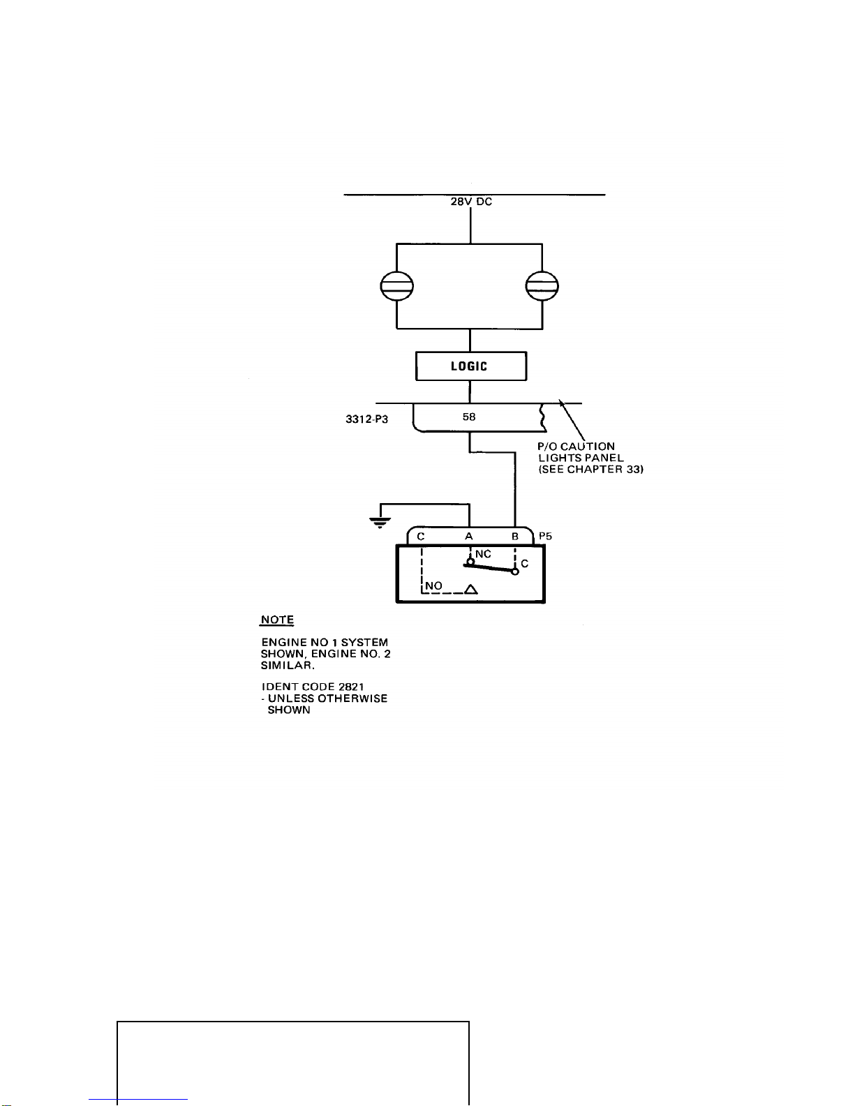
Refer to Figure 2.
The switch is provided with one contact set. The switch mechanism is calibrated to operate
the contact from C to N.O. on increasing fuel delivery pressure of 7.5 + or − 0.8 psig and from
C to N.C. at 5.5 + or − 0.8 psig decreasing pressure.
The N.C. contact is connected to ground and the N.O. contact is an open circuit.
With fuel delivery pressure above 7.5 psig, the ground is removed and the associated caution
light goes out.
Should the fuel delivery pressure fall below 5.5 psig, the caution light logic circuit is connected
to ground and the caution light comes on.
DSERIES 100
AIRCRAFT MAINTENANCE MANUAL
MASTER
EFFECTIVITY: See Pageblock 73−31−00 page 1 73−31−00 Page 1
Dec 20/2004

DSERIES 100
AIRCRAFT MAINTENANCE MANUAL
FUEL LOW PRESSURE WARNING
Figure 1
MASTER
EFFECTIVITY: See Pageblock 73−31−00 page 1 73−31−00 Page 2
Dec 20/2004
DSERIES 100
AIRCRAFT MAINTENANCE MANUAL
FUEL LOW PRESSURE WARNING
Figure 2
MASTER
EFFECTIVITY: See Pageblock 73−31−00 page 1 73−31−00 Page 3
Dec 20/2004


**ON A/C ALL FUEL FLOW INDICATING − DESCRIPTION AND OPERATION
1. General
Fuel flow indicating for the engine fuel and control installation consists of two identical, but
independent fuel flow indicating systems, one for each engine. Each system consists of a fuel
flow transmitter connected to a fuel flow indicator. The transmitters are mounted on the
engine casings and the indicators are located on the engine instrument panel in the flight
compartment.
The electrical circuit for each engine is powered from the 28 V dc bus, and protected by a
5−ampere FUEL FLOW IND ENG 1 (C5) left main bus or FUEL FLOW IND ENG 2 (Q5) right
main bus circuit breaker.
2. Description and Operation
Refer to Figure 1.
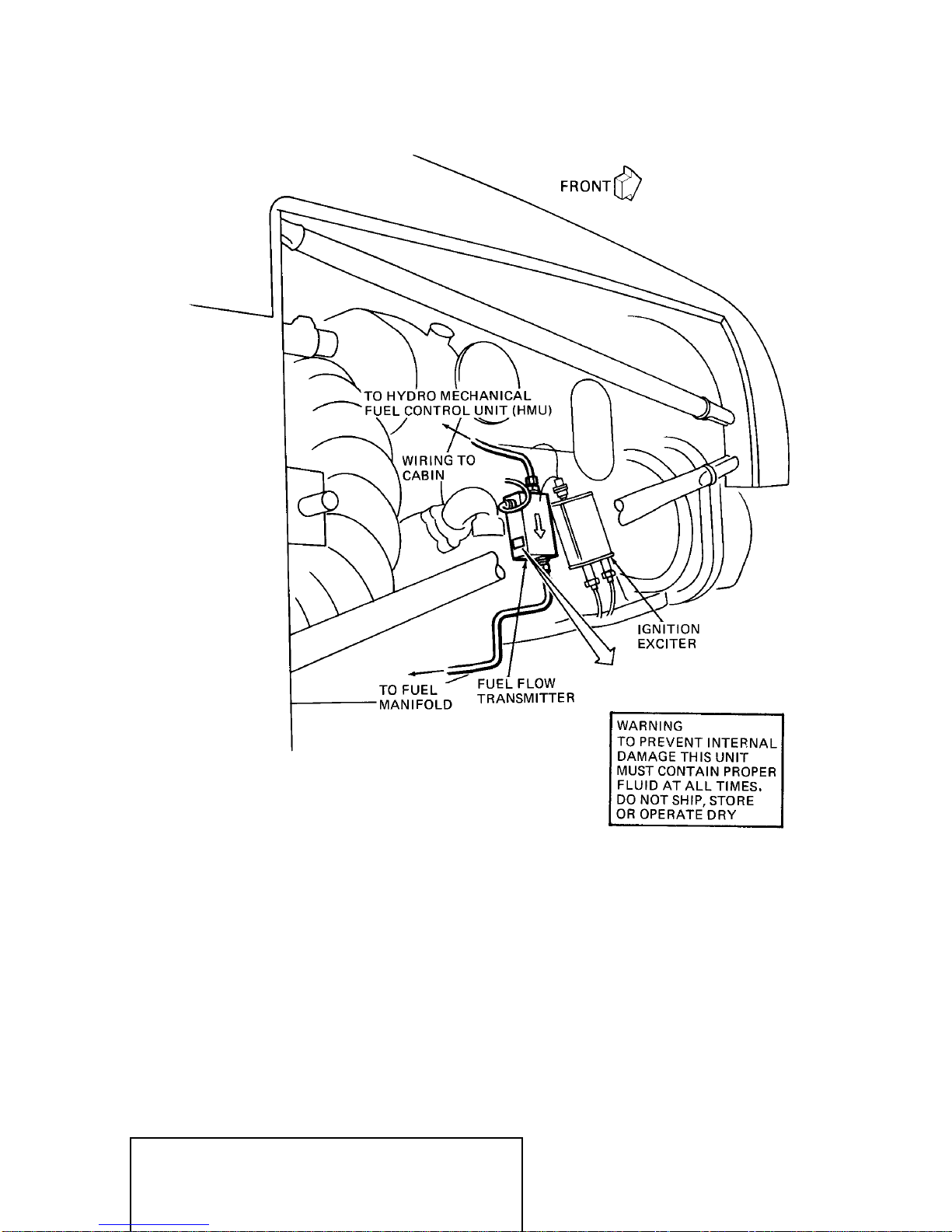
A. Fuel Flow Transmitter
A fuel flow transmitter installation consisting of a transmitter and a mounting bracket
assembly is attached to the engine front inlet case rear flange at approximately 3 o’clock
(viewed from rear of engine). The transmitter is connected into engine metered fuel lines
between the hydromechanical fuel control unit (HMU) and the fuel manifold and nozzles
installation of each engine fuel system.
A directional arrow, on the transmitter casing, points away from the HMU and provides
indication of required fuel flow direction. The bracket assembly and the transmitter are
provided with an uneven bolting pattern to prevent incorrect installation.
The transmitter is of the rotating impeller type and is connected to the associated
indicator by electrical wiring.
B. Fuel Flow Indicators
Refer to Figure 2 and Figure 3.
The fuel flow indicators are located on the engine instrument panel in the flight
compartment and are internally lighted by white lighting, powered from the 5 V dc lighting
system (refer to Chapter 33).
Each indicator receives an ac signal equivalent to fuel flow from its associated
transmitter and provides a fuel flow readout by means of a moving pointer against a fixed
dial and an equivalent digital display. A 0 to 5 V dc signal proportional to fuel flow is
relayed to the flight data recorder (refer to Chapter 31).
The digital display is of the 4−digit liquid crystal display (LCD) type. Pre mod 8−1/1101
aircraft incorporate a heater associated with LCD operation in each indicator. The
heaters are powered from the 28 V dc secondary buses, engine No. 1 IND LCD HTR
(S2) indicator heater from the left bus and engine No. 2 IND LCD HTR (A1) indicator
heater from the right bus (refer to Chapter 77). The heaters are temperature controlled to
ensure LCD operation at low temperature conditions in the flight compartment.
The indicator dial is marked FF PPH × 100 (KG/H × 100) and the scale is graduated in
major graduations in increments of 100 PPH (100 KG/H) between 0 and 1200 PPH (0
and 550 KG/H), with minor graduations in increments of 50 PPH (50 KG/H). Indicator for
engine No. 1 is powered by 28V dc L MAIN BUS (C5). Engine No. 2 by 28V dc R MAIN
BUS (Q5).
DSERIES 100
AIRCRAFT MAINTENANCE MANUAL
MASTER
EFFECTIVITY: See Pageblock 73−32−00 page 1 73−32−00 Page 1
Dec 20/2004

A test pushbutton is provided on the indicator, which when pressed, with power on,
causes the indicator to move to 1050 PPH (400 ±70 KG/H), indicated by a blue dot on
the face of the indicator dial and an equivalent digital display. Releasing the pushbutton
causes the pointer to fall to zero and a digital display of 0.0.
Loss of electrical power to the indicator causes the pointer to move off scale to below
zero and the digital display is blanked.
Mod 8/1738 introduces fuel flow indicators with specification changes as follows:
(1) FF (fuel flow) of 1200 PPH (550 KG/H) and higher (beyond indicator range) shall
read 1200 PPH (550 KG/H).
(2) Low range indication is extended from 80 PPH (35 KG/H) to 40 PPH (20 KG/H).
(3) The FDR outputs at pins J and K shall be 5V dc (max) for fuel flows of 1200 PPH
(550 KG/H) and higher.
(4) Normal fuel flow indications will be available without delay when fuel flow is reduced
below 1200 PPH (550 KG/H) or less.
DSERIES 100
AIRCRAFT MAINTENANCE MANUAL
MASTER
EFFECTIVITY: See Pageblock 73−32−00 page 1 73−32−00 Page 2
Dec 20/2004
DSERIES 100
AIRCRAFT MAINTENANCE MANUAL
FUEL FLOW TRANSMITTER INSTALLATION
Figure 1
MASTER
EFFECTIVITY: See Pageblock 73−32−00 page 1 73−32−00 Page 3
Dec 20/2004

DSERIES 100
AIRCRAFT MAINTENANCE MANUAL
FUEL FLOW (FF) INDICATING SYSTEM − SCHEMATIC
Figure 2
MASTER
EFFECTIVITY: See Pageblock 73−32−00 page 1 73−32−00 Page 4
Dec 20/2004

FUEL FLOW
INDICATOR
P5
J
K
L
M
T
A
C
B
S
F
G
H
E
N
P
U
V
R
5
FUEL FLOW
IND ENGINE 1
28V DC
L BUS
5V DC LTG
(REFER TO CHAPTER 33)
P3
1
3
2
50 TO 5V DC
OUTPUT TO
FLIGHT DATA
RECORDER DC REF
FUEL USED PULSE
2
1
0
34
5
FUEL FLOW
KG/H x 100
dam01_7332000_003.dg, gw, 31/10/01
1. Engine No. 1 indicating system shown, engine No. 2 system similar.
2. Identification code is 7331.
NOTE
INDICATOR FUEL FLOW (METRIC)
DSERIES 100
AIRCRAFT MAINTENANCE MANUAL
FUEL FLOW (FF) INDICATING SYSTEM (METRIC) − SCHEMATIC
Figure 3
MASTER
EFFECTIVITY: See Pageblock 73−32−00 page 1 73−32−00 Page 5
Dec 20/2004


**ON A/C ALL FUEL FLOW INDICATING − MAINTENANCE PRACTICES
1. General
A. The maintenance procedures that follow are for the:
–Removal and installation of the fuel flow indicator
–Removal and installation of the fuel flow transmitter
–Operational test of the fuel flow indicator.
2. Removal/Installation
A. Removal of the Fuel Flow Indicator
Refer to Figure 201.
WARNING: REMOVE ALL ELECTRICAL POWER FROM THE AIRCRAFT
BEFORE YOU DO MAINTENANCE. PUT WARNING PLACARD AT
THE EXTERNAL POWER RECEPTACLE AND IN FLIGHT
COMPARTMENT. THIS IS NECESSARY TO PREVENT
ELECTRICAL SHOCK TO PERSONS AND/OR DAMAGE TO THE
EQUIPMENT.
(1) Remove the electrical power from the aircraft (refer to AMM 12−00−05).
(2) Open, safety clip and tag the circuit breakers that follow:
(a) On the left DC circuit breaker panel:
–FUEL FLOW IND ENG 1 (C5)
–IND LCD HTR (S2)
(b) On the right DC circuit breaker panel:
–FUEL FLOW IND ENG 2 (Q5)
–IND LCD HTR (A1)
(3) Remove the fuel flow indicator (1) as follows:
(a) Loosen the top right and lower left screws (3), that attach the indicator (1),
approximately five turns.
(b) Push in the top right and lower left screws (3) to disengage the clamping
mechanism.
(c) Pull out the fuel flow indicator (1) from the instrument panel (4).
(d) Disconnect the electrical connector (2), and remove the indicator (1).
(e) Put a protective cap on the electrical connector (2).
B. Installation of the Fuel Flow Indicator
Refer to Figure 201.
(1) Make sure that the aircraft is in the same configuration as in the removal procedure.
(2) Install the fuel flow indicator (1) as follows:
(a) Remove the protective cap from the electrical connector (2). Connect the
electrical connector (2) to the indicator (1).
(b) Insert and align the indicator (1) on the instrument panel (4).
DSERIES 100
AIRCRAFT MAINTENANCE MANUAL
MASTER
EFFECTIVITY: See Pageblock 73−32−00 page 201 73−32−00 Page 201
Jan 15/2010
(c) Tighten the top right and lower left screws (3).
(3) Remove the safety clips and tags and close the circuit breakers that follow:
(a) On the left DC circuit breaker panel:
–FUEL FLOW IND ENG 1 (C5)
–IND LCD HTR (S2)
(b) On the right DC circuit breaker panel:
–FUEL FLOW IND ENG 2 (Q5)
–IND LCD HTR (A1)
(4) Remove all the tools, equipment and unwanted materials from the work area.
(5) Do the operational test of the fuel flow indicator (refer to Para 3. A).
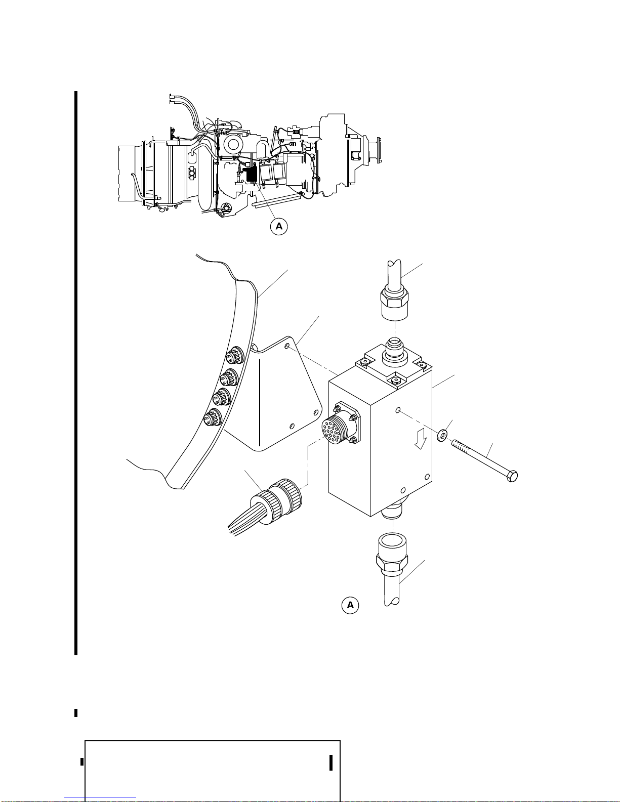
C. Removal of the Fuel Flow Transmitter
Refer to Figure 202
Equipment and Materials:
–Fuel resistant container, commercially available
WARNING: REMOVE ALL ELECTRICAL POWER FROM THE AIRCRAFT
BEFORE YOU DO MAINTENANCE. PUT WARNING PLACARD AT
THE EXTERNAL POWER RECEPTACLE AND IN FLIGHT
COMPARTMENT. THIS IS NECESSARY TO PREVENT
ELECTRICAL SHOCK TO PERSONS AND/OR DAMAGE TO THE
EQUIPMENT.
(1) Remove the electrical power from the aircraft (refer to AMM 12−00−05).
(2) For the No. 1 fuel flow transmitter, open the access panel 414AR to get access to
the transmitter (refer to AMM 06−40−10).
(3) For the No. 2 fuel flow transmitter, open the access panel 424AR to get access to
the transmitter (refer to AMM 06−40−10).
(4) Remove the fuel flow transmitter (1) as follows:
(a) Disconnect the electrical connector (2) from the fuel flow transmitter (1). Put a
protective cap on the electrical connector (2).
(b) Put a container below the fuel flow transmitter (1) to collect the fuel that spills.
(c) Disconnect the top fuel line (3) from the fuel flow transmitter (1). Install a
protective cap on the open end of the top fuel line (3).
(d) Disconnect the bottom fuel line (4) from the fuel flow transmitter (1). Install a
protective cap on the open end of the bottom fuel line (4).
(e) Hold the fuel flow transmitter (1) and remove the bolts (5) and washers (6) that
attach the fuel flow transmitter (1) to the bracket (7).
(f) Remove the fuel flow transmitter (1).
(g) Install protective caps on the electrical connector and the open ends of the fuel
flow transmitter (1).
D. Installation of the Fuel Flow Transmitter
Refer to Figure 202
DSERIES 100
AIRCRAFT MAINTENANCE MANUAL
MASTER
EFFECTIVITY: See Pageblock 73−32−00 page 201 73−32−00 Page 202
Jan 15/2010

Equipment and Materials:
–Fuel resistant container, commercially available
(1) Make sure that the aircraft is in the same configuration as in the removal procedure.
(2) Install the fuel flow transmitter (1) as follows:
(a) Put a container below the fuel flow lines (3) and (4) to collect the fuel that
spills.
(b) Remove the protective caps from the electrical connector and the open ends of
the fuel flow transmitter (1).
(c) Hold the fuel flow transmitter (1) near the bracket (7) in the correct position
such that the flow arrow on the fuel flow transmitter (1) points down. Install the
fuel flow transmitter (1) to the bracket (7) with the washers (6) and bolts (5).
(d) Torque the bolts (5) to 18 to 22 pound−inches (2.03 to 2.49 N·m) (refer to
AMM 20−14−01).
(e) Remove the protective cap from the bottom fuel line (4). Connect the bottom
fuel line (4) to the fuel flow transmitter (1).
(f) Remove the protective cap from the top fuel line (3). Connect the top fuel line
(3) to the fuel flow transmitter (1).
(g) Remove the protective cap from the electrical connector (2). Connect the
electrical connector (2) to the fuel flow transmitter (1).
(3) Remove all the tools, equipment and unwanted materials from the work area.
(4) Do the engine start procedure for the related engine (refer to AMM 71−00−00).
(5) Examine all the connections at the fuel flow transmitter and the tube assemblies for
signs of fuel leaks.
(6) Do the engine shutdown procedure for the related engine (refer to AMM 71−00−00).
(7) For the No. 1 fuel flow transmitter, close the access panel 414AR (refer to AMM
06−40−10).
(8) For the No. 2 fuel flow transmitter, close the access panel 424AR (refer to AMM
06−40−10).
DSERIES 100
AIRCRAFT MAINTENANCE MANUAL
MASTER
EFFECTIVITY: See Pageblock 73−32−00 page 201 73−32−00 Page 203
Jan 15/2010

0
2
468
10
12
PPH x 100
FF 1. Indicator.
2. Electrical connector.
3. Screw.
4. Instrument panel.
LEGEND
0
2
468
10
12
PPH x 100
FF
4
32
1
3
dam01_7332004_002.dg, gw, aug14/2008
DSERIES 100
AIRCRAFT MAINTENANCE MANUAL
Fuel Flow Indicator − Removal and Installation
Figure 201
MASTER
EFFECTIVITY: See Pageblock 73−32−00 page 201 73−32−00 Page 204
Jan 15/2010
1
2
3
4
5
6
dam01_7332002_001.dg, vk, jul24/2009
7
FRONT INLET CASE
REAR FLANGE (REF)
1. Fuel flow transmitter.
2. Electrical connector.
3. Fuel line.
4. Fuel line.
5. Bolt.
6. Washer.
7. Bracket.
LEGEND
DSERIES 100
AIRCRAFT MAINTENANCE MANUAL
FUEL FLOW TRANSMITTER − REMOVAL/INSTALLATION
Figure 202
MASTER
EFFECTIVITY: See Pageblock 73−32−00 page 201 73−32−00 Page 205
Jan 15/2010

3. Adjustment/Test
A. General
(1) The maintenance procedure that follows is to make sure that the fuel flow indicators
operate correctly. The test procedure includes the operational test of the fuel flow
indicator.
B. Operational Test of the Fuel Flow Indicator
WARNING: MAKE SURE THAT ALL PERSONS IN THE AREA OF THE
AIRCRAFT ARE TOLD BEFORE THE ELECTRICAL SYSTEM IS
ENERGIZED. IF YOU DO NOT DO THIS, YOU CAN CAUSE
INJURIES TO PERSONS OR DAMAGE TO EQUIPMENT.
(1) Apply electrical power to the aircraft (refer to AMM 12−00−05).
(2) Push and hold the test button on the indicator. Make sure that:
–The pointer moves to the blue dot on the indicator face.
–The digital display of the indicator reads 1050.
(3) Release the test button. Make sure that:
–The pointer of the indicator moves to zero.
–The digital display of the indicator reads 0000.
(4) Remove the electrical power from the aircraft (refer to AMM 12−00−05).
DSERIES 100
AIRCRAFT MAINTENANCE MANUAL
MASTER
EFFECTIVITY: See Pageblock 73−32−00 page 201 73−32−00 Page 206
Jan 15/2010

**ON A/C ALL
FUEL TEMPERATURE INDICATING − DESCRIPTION AND OPERATION
1. General
Refer to Figure 1.
The fuel temperature indicating system for the fuel feed systems of both engines consists of
temperature transmitter for each engine connected by electrical wiring to a dual indicator
which serves both engines.
2. Description and Operation
A. Fuel Temperature Transmitter
A fuel temperature transmitter is located in an engine supplied tapping upstream of the
engine driven pump (see ENGINE FUEL AND CONTROL − GENERAL, Figure 1). The
transmitter is a standard electrical resistance type component, in which resistance varies
in direct proportion to sensed temperature.
B. Fuel Temperature Dual Indicator
The fuel temperature indicator for both engines is mounted on the engine instrument
panel in the flight compartment.
The indicator contains separate circuits and indicating mechanisms for engine No. 1 and
engine No. 2, which receive separate inputs from the associated transmitter. The circuits
are separately powered from the 28V dc buses and protected by 5−ampere FUEL TEMP
ENG 1 (N4) left secondary bus and FUEL TEMP ENG 2 (E4) right secondary bus, circuit
breakers. Lighting for the indicator is from the 5V dc lighting system (refer to Chapter
33).
The indicator provides a readout of fuel temperature by means of moving pointers
against a fixed dial. The pointers for engines No. 1 and No. 2 are mounted on concentric
shafts and identified 1 and 2 by a marking on the dial for each half scale.
The indicator dial is marked FUEL TEMP with the two separate half scales marked
degrees C and graduated from −40 to +80 degrees, with major graduations increments
of 40 degrees and minor graduations in increments of 10 degrees.
On Pre Mod 8/0861 aircraft the scale is provided with a green arc from +11 to +43
degrees with a red limit mark at 57 degrees, and yellow arcs +43 to +57 degrees and
−40 to +11 degrees.
On Mod 8/0861 aircraft, the scale is provided with a green arc from +11 degrees to +57
degrees, yellow arc from −40 degrees to +11 degrees and red limit mark at 57 degrees.
In the event of indicator power supply failure, the pointer(s) of the affected circuit(s)
move off scale below −40 degrees.
DSERIES 100
AIRCRAFT MAINTENANCE MANUAL
MASTER
EFFECTIVITY: See Pageblock 73−33−00 page 1 73−33−00 Page 1
Dec 20/2004

DSERIES 100
AIRCRAFT MAINTENANCE MANUAL
FUEL TEMPERATURE INDICATING SCHEMATIC
Figure 1
MASTER
EFFECTIVITY: See Pageblock 73−33−00 page 1 73−33−00 Page 2
Dec 20/2004
Table of contents


