APCO Aviation NRG Pro II User manual

www.apcoaviation.com
2
CONTENTS:
1NRG PRO II 4
2NRG XC II 5
3DETAILED COMPARISON (XC II vs. PRO II) 6
4NRG PRO II TECHNICAL DATA 8
5NRG XC II TECHNICAL DATA 9
6DISCLAIMER OF LIABILITY 10
7CONSTRUCTION 10
8MATERIALS 10
9FLEXON® Batten system: 11
10 TRIMMING 11
11 HARNESS 12
12 SPEED SYSTEM 12
12.1 ASSEMBLY & ADJUSTMENT 12
13 EMERGENCY PARACHUTE ATTACHMENT 12
14 RISERS 12
15 TRIMMERS 15
16 OAA (One Action Acceleration) 16
17 HIT VALVES (High speed In-Take) 17
18 SRS –Stall Recovery System 18
1ABS - Automatic Balance System (on NRG XC II) 19
2INSPECTION 19
2.1 GENERAL 19
3ANNUAL / PERIODICAL AIRWORTHINESS INSPECTION 20
4BEFORE THE FIRST FLIGHT 21
BRAKE SETTING 21
4.1 Brake Operation 22
4.2 FIRST CHECK AND PREFLIGHT INSPECTION 22
4.3 REGULAR INSPECTION CHECKS 22
4.4 LINE MAINTENANCE 22
5PARAGLIDING 23
5.1 TAKE OFF 23
5.1.1 LAYOUT 23
5.1.2 ALPINE LAUNCH OR FORWARD LAUNCH 24
5.1.3 STRONG WIND AND REVERSE LAUNCH 24
5.1.4 TOW OR WINCH LAUNCHING 24
5.2 FLIGHT TECHNIQUES 24
5.2.1 FLYING SPEED 24
5.2.2 THERMAL FLYING 25
5.2.3 ASYMMETRIC COLLAPSE 25
5.2.4 CRAVAT 26
5.2.5 FRONT STALL OR SYMMETRIC COLLAPSE 26
5.2.6 B-STALL 26
5.2.7 BIG EARS 26
5.2.8 DEEP STALL OR PARACHUTAL STALL 26
5.2.9 SPIRAL DIVES 27
5.2.10 STRONG TURBULENCE 27
5.2.11 STEERING NOT FUNCTIONING 27
5.2.12 LANDING 28
5.2.13 TREE LANDING 28
5.2.14 WATER LANDING 28
6POWERED FLYING 28
6.1 FIRST FLIGHTS 29
6.2 TAKE-OFF 29
6.2.1 FORWARD LAUNCH 29
6.2.2 REVERSE LAUNCH (In strong wind) 30
6.2.3 CLIMBING 31
6.3 LEVEL FLIGHT 32
6.4 TRIMMERS AND SPEED-SYSTEM SETTINGS 33
6.5 LANDING 33
6.5.1 POWER OFF LANDING 33
6.5.2 POWERED LANDING 33
7PACKING 34
8MAINTENANCE & CLEANING 35
8.1 BUTT HOLES (Velcro closure on trailing edge tip) 35
9STORAGE 35
10 DAMAGE 36
11 GENERAL ADVICE 36
12 NRG PRO II/NRG XC II SKETCHES 37

www.apcoaviation.com
3
WARNING
This is not a training manual. It is extremely dangerous to yourself and others to
attempt to fly this or any paraglider without first completing a flying course given by a
qualified instructor.
Apco Aviation's gliders are carefully manufactured and inspected by the factory.
Please use the glider only as described in this manual. Do not make any changes to the
glider.
AS WITH ANY SPORT - WITHOUT TAKING THE APPROPRIATE PRECAUTIONS,
PARAGLIDING CAN BE DANGEROUS.

www.apcoaviation.com
4
1 NRG PRO II
The APCO NRG Pro II is the ultimate answer to the fast growing, challenging segment of purpose built wings designed
for professional slalom racing.
NRG Pro II is a complete redesign of the previous NRG - and is now a faster, more aggressive wing with pylon racing
performance and spirit!
The pylon racing turning sequence of:
» :: FULL SPEED BAR TO THE PYLON » RELEASE SPEED BAR » TIGHT TURN » FULL SPEED BAR TO NEXT
PYLON :: »
has been perfected to a point where it is only the pilot who can limit the wing and never the opposite!
HIT VALVES® - A highly stable, full reflex profile with our HIT valves incorporated, allows pushing this wing beyond any
familiar boundaries.
OAA® system - incorporated into NRG Pro II risers allows for use of full speed range using the speed bar only.
The change from trim speed to fully accelerated is faster than ever before with the OAA system.
For normal flight OAA can be easily disengaged, allowing for operation of trimmers separate from speed bar.
2D Steering - allows for one hand use of both tip steering and main brakes.
The NRG PRO is the favorite wing for most professional pilots, but now it's time to take it up to the next level. NRG Pro
II is an adrenaline junkies dream and still rock solid safe!
NRG Pro II takes-off and lands at slower speed than you would expect, making flying easy. All thanks to new highly
efficient reflex profile.
NRG Pro II will excite every experienced pilot - you will be infected by the racing virus instantly. The adrenaline rush will
go through the roof and your heart rate will match the speed of the wing.
NRG Pro II purpose built for speed and agility to win the race, or just for low level ground skimming and fun.
WARNING: DO NOT! test fly this wing, unless you are ready to buy it!
This wing is highly addictive!

www.apcoaviation.com
5
2 NRG XC II
NRG XC was designed on the foundations of the NRG PRO. It has the same advantages of a professional slalom racing
wing in a XC oriented package!
It is a small, safe wing that allows fast flying for cross country ventures, expanding the possibilities for any experienced
pilot.
NRG XC II- is a second generation of NRG XC, improved in all parameters of the wing.
One of the main upgrades we made was incorporation of the ABS® - Automatic Balance System - Industry first,
pioneered by APCO.
Following the market feedback from Force II about ABS®, it was the natural next step for NRG XC. It improved the wing
dramatically, shaping it as an even better XC oriented wing and polarizing the difference between flying at trim speed
and accelerated flight.
At trim speed - always restless, super agile, fast wing with quick responses and incredible flying rush.
At accelerated flight the ABS® system comes into play automatically - generating a stable, efficient cross country
machine.
ABS® is a system which automatically and gradually pulls down the tip steering as you release the trimmers and push
the speed bar. This action stabilizes the wing , cancelling roll movement, "planting" the pilot under the center of the
canopy.
This outstanding roll stability gives the pilot the best and most efficient flying path at high speeds! It is on cross country
flights or when chasing down a friend that the ABS® system comes into play.
The ABS® system will get you from point A to B in the fastest way possible with no pilot input.
On trim speed, the system is not activated, allowing dynamic flight tuned for thrill and agility as should be with a true
slalom racing wing.
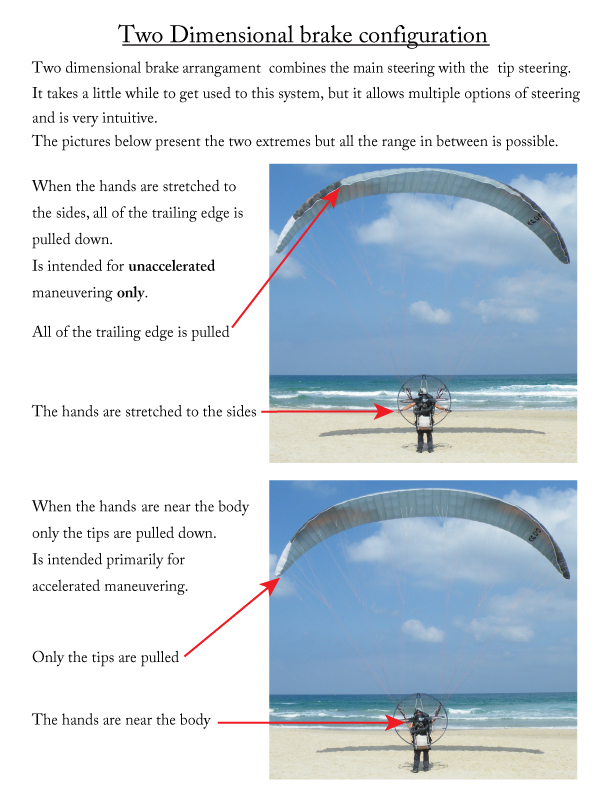
With the ABS® tip steering handles together with the main 2D brakes in hand your every touch will be rewarded with an
energetic and precise response , satisfying even the most demanding pilots!
Additional difference between the XC and the PRO is the line set. The NRG XC II uses sheathed lines for improved
durability on harsh take-off surfaces. Top lines are are life-time warrantied, embedded hook-in points EHP® for improved
aerodynamics.
The SRS® system will come into play whenever the pilot makes an error that causes stall behavior. It will automatically
protect the pilot by lowering the angle of attack if the wing goes into a stall/parachutal/spin.
We have recently received warm praise from a pilot noticing how the SRS® saved him from stall/spin situation when
exiting a spiral incorrectly. See video »
NRG XC II takes-off and lands at slower speed than you would expect, making flying easy. All thanks to new highly
efficient reflex profile.
NRG XC II will excite every experienced pilot - you will be infected by the xc racing virus instantly.
NRG XC II purpose built for speed and agility, fun flying, and long distance speed racing.
WARNING: DO NOT! test fly this wing, unless you are ready to buy it!
This wing is highly addictive!

www.apcoaviation.com
6
3 DETAILED COMPARISON (XC II vs. PRO II)
NRG XC II
NRG PRO II
Description
Cross Country wing - easy to handle, take-off
and land.
Fast and agile at trim speed.
Stable and more relaxed in any
accelerated flight mode (trimmers or
speed bar)
Slalom racing wing –extremely manoeuvrable and
responsive wing. Designed to allow the fastest
possible transition between trim speed to fully
accelerated and back to trim speed. Highly defined
and pronounced reflex profile for safety in extreme
flying.
Aimed at
Experienced pilots, looking for a thrilling cross
country wing which delivers more speed and
adrenalin than the average xc wing.
Very experienced pilots/professionals who can
handle its responsiveness to the lightest of input.
Pilots looking for the ultimate paramotor wing for
slalom racing/ACRO flying/adrenalin.
Build
differences
Fully sheathed lines for easy handling and
durability
Unsheathed competition lines for maximum
performance.
Unique Features
ABS -
Automatic
Balance
System
✔- improved stability in accelerated flight
- Removed for the highest agility at any flight
speed
SRS –Stall
Resistance
System
✔- Easier launch and safety due to stall
resistance
✘- Removed for quicker transition from trim speed
to accelerated and back to trim speed
Tip Steering
handles
✔- Included as standard. Additional steering
option for ease of use in XC flights
✘- Removed for use with 2D system only for
maximum agility and wing control
2D Steering
✔
WSS - Wind
Scoop System
✔
✔
EHP -
Embedded
hook in point
✔
✔
OAA –One
Action
Acceleration
✔
✔
HIT Valves
✔
✔
Flexon
battens
✔
✔
Ball bearing
pulleys
✔
✔

www.apcoaviation.com
8
4 NRG PRO II TECHNICAL DATA
Size
16.5
17.5
18.5
19.5
20.5
22.0
Cells
50
52
54
50
52
54
Area m2
16.52
17.5
18.48
19.47
20.5
21.80
Area (projected) m2
13.81
14.63
15.45
16.27
17.14
18.22
Span (incl. Stabiliser) m
9.57
10.05
10.53
10.39
10.91
11.43
Span (projected) m
7.49
7.86
8.24
8.13
8.53
8.95
Aspect Ratio
5.55
5.77
5.99
5.55
5.77
5.99
Aspect Ratio (projected)
4.06
4.22
4.38
4.06
4.22
4.38
Pilot Weight (all up) free flight [kg]
70-90
70-100
70-110
70 –120
70 - 130
70-140
Pilot Weight (all up + paramotor unit) [kg]
80-105
90-125
100-140
110-155
120-170
130-180
Weight of Canopy Kg
4.18*
4.45*
4.72*
4.92*
5.21*
5.57*
Root Cord m
2.07
2.07
2.07
2.25
2.25
2.25
Tip Cord m
0.4
0.4
0.4
0.44
0.44
0.44
Length of Lines on B m
5.78
6.03
6.28
6.27
6.55
6.82
Total length of line used m
305
325
348
331
353
378
*Approximate Weight
CERTIFICATION
DGAC
DGAC
DGAC
DGAC
DGAC
DGAC
LINE MATERIALS
Material
Diameter
Strength
Top
Dyneema
1.0mm
90kg
Mid; (a1,b1,c1,d1)
Vektran
1.0mm
153kg
Mid;,a,b,c,d,**Brake
Vektran
0.9mm
115kg
Bottom A3;A5;B3;B5
Super Aramid
1.4mm
254kg
Bottom A1;B1
Super Aramid
1.6mm
325kg
Bottom C,D,St
Super Aramid
1.0mm
137kg
Brake Cascades; st top
Vektran
0.6mm
50kg
Steering Lines
Polyester
2.0mm
85kg
**See Line Table
FABRIC
Sail Cloth
"Zero Porosity" Ripstop Nylon
PERFORMANCE DATA
V-min.
27km/h
V-trim (-) / V-trim (0)
39/48 km/h
V-trim off
56 km/h
V-max.
77 km/h
Min Sink (at optimum wing loading)
1.4 m/s

www.apcoaviation.com
9
5 NRG XC II TECHNICAL DATA
Size
16.5
17.5
18.5
19.5
20.5
22.0
Cells
50
52
54
50
52
54
Area m2
16.52
17.5
18.48
19.47
20.5
21.80
Area (projected) m2
13.81
14.63
15.45
16.27
17.14
18.22
Span (incl. Stabiliser) m
9.57
10.05
10.53
10.39
10.91
11.43
Span (projected) m
7.49
7.86
8.24
8.13
8.53
8.95
Aspect Ratio
5.55
5.77
5.99
5.55
5.77
5.99
Aspect Ratio (projected)
4.06
4.22
4.38
4.06
4.22
4.38
Pilot Weight (all up) free flight [kg]
70-90
70-100
70-110
70 –120
70 - 130
70-140
Pilot Weight (all up + paramotor unit)[kg]
80-105
90-125
100-140
110-155
120-170
130-185
Weight of Canopy Kg
4.18*
4.45*
4.72*
4.92*
5.21*
5.57*
Root Cord m
2.07
2.07
2.07
2.25
2.25
2.25
Tip Cord m
0.4
0.4
0.4
0.44
0.44
0.44
Length of Lines on B m
5.78
6.03
6.28
6.27
6.55
6.82
Total length of line used m
305
325
348
331
353
378
*Approximate Weight
CERTIFICATION
DGAC
DGAC
DGAC
DGAC
DGAC
DGAC
LINE MATERIALS
Material
Diameter
Strength
Top
Dyneema
1.0mm
90kg
Mid; (a1,b1,c1,d1)
Super Aramid
1.5mm
150kg
Mid;,a,b,c,d,St
Super Aramid
1.2mm
120kg
Bottom A3;A5;B3;B5
Super Aramid
1.8mm
230kg
Bottom A1;B1
Super Aramid
1.9mm
320kg
Bottom C,D,St
Super Aramid
1.5mm
150kg
Brake Cascades;st top
Dyneema
1.1mm
95kg
Steering Lines
Polyester
2.0mm
85kg
FABRIC
Sail Cloth
"Zero Porosity" Ripstop Nylon
PERFORMANCE DATA
V-min.
27km/h
V-trim (-) / V-trim (0)
39/48 km/h
V-trim off
56 km/h
V-max.
77 km/h
Min Sink (at optimum wing loading)
1.4 m/s

www.apcoaviation.com
10
6 DISCLAIMER OF LIABILITY
Taking into consideration the inherent risk in paragliding or hang gliding, (free flying and
motorized), it mustbe expressly understood that the manufacturer and seller do not assume
any responsibility for accidents, losses and direct or indirect damage following the use or
misuse of this product.
APCO Aviation Ltd. is engaged in the manufacture and sale of hang gliding, paragliding,
motorized Para/hang gliding and emergency parachute equipment.
This equipment should be used under proper conditions and after proper instruction from a
qualified instructor. APCO Aviation Ltd. has no control over the use of this equipment and a
person using this equipment assumes all risks of damage or injury.
APCO Aviation Ltd. disclaims any liability or responsibility for injuries or damages resulting
from the use of this equipment.
The glider is designed to perform in the frame of the required class as certified.
7 CONSTRUCTION
The glider is constructed with a top and bottom surface, connected by ribs.
One top and bottom panel, together with the connecting ribs is called a cell.
Each cell has an opening on the front lower part. The cells fill with air forcing the panels to
take the shape dictated by the airfoil (rib) section.
On either side the wing ends in a stabilizer or wing tip, which provides straight-line (Yaw)
stability and produces some outward lift to keep the span-wise tension.
The front part of the ribs use APCO's FLEXON batten system to keep the leading edge
shaped at high speeds and in turbulent air. They also improve the performance and the
launch characteristics of the glider.
The line hook-up points are made of Dyneema and imbedded in the bottom surface of the
wing for minimal drag and maximum performance.
8 MATERIALS
The glider is made from tear resistant Ripstop Nylon cloth, which is P.U. coated to zero
porosity and then siliconized to give the fabric high resistance to the elements. Different
cloth is used for the top, bottom and ribs due to their different functions.
The lines are made of superaramid covered with a polyester sheath for protection against
UV, wear and abrasion.
The bottom section of the brake lines are made of polyester because of its better mechanical
properties.

www.apcoaviation.com
11
The maillon quick links that attach the lines to the risers are made of stainless steel.
9 FLEXON® Batten system:
New generation FLEXON ® batten system incorporated (see below) in the leading edge of
the ribs, insuring perfect profile shape (instead of traditional Mylar reinforcement). FLEXON
® battens reduce the weight of the glider by an additional 500gr. and unlike Mylar
reinforcement will guarantee no deterioration in performance or launch.
Additional advantage of FLEXON batten is that it is practically indestructible, safeguarding
the performance and launch over the lifespan of the glider.
How it Works:
10 TRIMMING
All Apco gliders are trimmed for optimum performance combined with unsurpassed safety.
It is very important not to re-trim or tamper with any of the lines or risers as this may alter
the performance and safety. Trimming of the brake line should be done in accordance with
this manual and carefully checked before flying.

www.apcoaviation.com
12
11 HARNESS
All of Apco's gliders are developed with the use of ABS (Automatic Bracing System) type
harnesses without cross bracing. We recommend the use of an ABS harness with all our
gliders. All certified harnesses can be used with our gliders. For best safety and performance
we recommend an Apco harness equipped with a Mayday emergency parachute.
CAUTION:
WE RECOMMEND NOT TO USE CROSS BRACING STRAPS.
APCO GLIDERS ARE DEVELOPED AND TESTED WITHOUT THE USE OFCROSS
BRACING. USING AN ABS HARNESS WITH CHEST STRAP SET AT THE
SPECIFIED WIDTH (CHECK THE CERTIFICATION STICKER ON YOUR GLIDER)
WILL RESULT IN THE HIGHEST PASSIVE SAFETY ON YOUR GLIDER.
12 SPEED SYSTEM
12.1ASSEMBLY & ADJUSTMENT
Apco gliders are supplied with a speed system compatible with most harnesses on the
market today. Follow your Harness Manual for connecting your speed system. Do a hang
test to ensure that the adjustment is correct. Flying with a speed system adjusted too short
will cause it to be applied all the time, which can be dangerous.
WARNING:
The use of the speed system in turbulent conditions or close to the ground is dangerous.
While flying with the accelerator, the glider has a reduced angle of attack and is therefore
more susceptible to turbulence and may collapse or partially deflate. Gliders react faster
when accelerated and may turn more. The accelerator should immediately be released in
this case.
13 EMERGENCY PARACHUTE ATTACHMENT
It is recommended to use a certified rescue parachute when flying. Attaching the rescue
parachute should be done in accordance with the recommendation of the harness and
reserve parachute manufacturer.
14 RISERS
The NRG PRO II is supplied with risers featuring a split A riser. The 1st A-riser attaches to
the central two A lines (A1 & A3). The second A-riser is attached to the outermost A line
(A5). At no time should the pilot change the risers or use risers not intended for this specific
glider as this will affect the performance and safety of the glider.
The riser is equipped with both an accelerator and trimmers with two hook-in points to
accommodate torque compensation for left and right prop rotation

www.apcoaviation.com
16
16 OAA (One Action Acceleration)
OAA is an innovative system that stands for "One action acceleration system - OAA".
The OAA allows pilots to simultaneously operate both the speed system and the trimmer
for optimized angle of attack at any given speed. With OAA, when using the speed system,
the trimmers are released gradually according to the position of the speed bar. This allows
for a larger speed range that can be fully used in one swift action of the speed bar.
In order to engage the OAA one must detach the Brummel hooks connected to the rear
risers below the trimmers. Prior to using the speed system one must move the
trimmers to the neutral position (all risers level).
To disengage the OAA one must reattach the Brummel hooks on the rear riser.
When operating the speed system with the OAA disengaged one must release the
trimmers open before activating the speed system.

www.apcoaviation.com
17
17 HIT VALVES (High speed In-Take)
The NRG PRO II is equipped with an Active HIT Valve system (patent pending) to improve
the overall performance and safety of the wing especially during accelerated flight.
The valve system allows maximum inflow of air when the glider acquires a lower angle of
attack while accelerated. HITvalves open and close in flight to increase the internal pressure
of the glider.
For the valves to work properly it is important to keep them wrinkle free especially in sub
zero temperatures. Make sure the valves are lying flat and are in the closed position when
you fold the glider. Before launch the pilot should check all the valves and verify that they
are flat and cover the entire area of the mesh opening. Creased and wrinkled valves will not
adversely affect the safety of the wing.

www.apcoaviation.com
18
18 SRS – Stall Recovery System
The NRG XC II features a new, innovative, riser design allowing the pilot to slow down the
glider to minimum speed without risking getting caught in deep stall ( parachutal ). The SRS
(patent pending) takes advantage of simple yet proven aeronautical and physical principles.
When flying, most of the load is applied to the front third of the wing. This means that the A
lines bear significantly more load than the C+D lines together. However, when the glider is
in deep stall ( parachutal ), the load is distributed almost evenly along the wing chord. Thus,
in parachutal, the load on the C+D lines is considerably higher than on the A lines. Using
this principle, we designed a self-compensating angle of attack (AofA) system based on a
sliding riser concept.
The C+D riser join the A risers and slide in opposite direction. In flight, the A riser is taut and
pulls the C+D to trim position. When forced into parachutal, The C+D riser elevate and pull
down the A riser, accelerating the glider out of parachutal. Once recovered, the risers
automatically resume trim position.

www.apcoaviation.com
19
1 ABS - Automatic Balance System (on NRG XC II)
Industry first, pioneered by APCO. ABS is a system which automatically and gradually
pulls down the tip steering as you release the trimmers and or push the speed bar.
This action stabilizes the wing , cancelling roll movement, "planting" the pilot under the
center of the canopy.
The system operates automatically and there is no need for the pilot to activate it.
The system integrates the tip steering handles, which are held by magnets and press
buttons. It is recommended to secure the press buttons after each landing to avoid clutter.
*The system comes tuned from the factory, It is Not recommended to change the
location of the contacts (Knots on the ABS lines).
2 INSPECTION
2.1 GENERAL
Pilots, please insure that your glider has been test flown and fully checked by your
dealer before taking it into your possession.
Verify that the dealer checked and confirms that the glider is airworthy.
In case of use of the wing in combination with trike:
Due to the very wide assortment of trikes on the market with different set up and
design, it is necessary to verify that the specific trike can be successfully coupled
with the wing.
Please make sure your dealer performs the following procedures before first flight:
A. It was checked with APCO that the specific trike can be flown with your new
wing.
In case the specific combination is not checked by APCO –your dealer must take
the following necessary steps:
B. Wing to be fully inspected by the dealer as in the paragraph above
C. Wing to be ground handled and visually checked while inflated.
D. Connection method to the trike is in line with APCO's recommendation according
to the sketch below. Pilot can reach both main brake handles and tip
steering handles (if available).
E. Before first take-off perform "taxiing" test on the ground slowly rolling with the
wing checking all aspects of the set-up without actually taking off. (Including
Roll/yaw stability, pitch stability, stall tendency, brake response etc.)
F. Only once the wing passes the taxiing test –then the next step is to make the
actual test flight to make sure trike and wing are correctly coupled and the
system is airworthy.
G. Take the wing into your possession only after your dealer confirms that wing is
airworthy when coupled with your trike.

www.apcoaviation.com
20
3ANNUAL / PERIODICAL AIRWORTHINESS INSPECTION
It is highly recommended that your glider (and other equipment), undergo a Periodical
Airworthiness Inspection which is to be done by Apco, or an Apco approved / appointed service
centre.
This is recommended to be done every 24 months or every 100 hours, whichever comes first.
This recommendation is in line with Israeli regulations, binding in Israel. as an alternative, we
suggest for you to follow the regulations set by your national authorities.
POROSITY:
Porosity is measured with a calibrated Porosimeter. It should be measured in at least 5 different
places on the upper surface. Below is an example of the sections we test at Apco. The upper
surface, at 20-35% chord (from L/E) is most prone to becoming porous, and is thus the most
important section to test. It is also important to test the different cloth types, and different colours
used.
LINE MAINTENANCE
Superaramide lines are known to be sensitive to the influence of the elements. They must be
carefully inspected periodically. In his/her own interest, the pilot must observe the following
points to ensure maximum performance and safety from the glider. Avoid sharp bending and
squeezing of lines. Take care that people do not step on the lines. Do not pull on the lines if they
are caught on rocks or vegetation. Avoid getting the lines wet. If they do get wet, dry them as
soon as possible at room temperature and never store them wet.
One line of each line group (a, b, c, upper and lower) must be tested for minimum 50% of the
rated strength. if the line fails under the load test or does not return to its specified length all the
corresponding lines must be replaced. never replace lines with different diameter or type of lines
as all gliders were flight and load tested for safety in their original configuration. Changing line
diameter/strengths can have dangerous / fatal consequences.
Professional use of gliders: towing, tandem, schooling and competition flying requires more
frequent line inspection and replacement of A, B, C, D and brake lines. For replacement lines
please refer to our online direct line services.
This manual suits for next models
1
Table of contents
Other APCO Aviation Aircraft manuals