De Liftfabriek Shuttle User manual

SHUTTLE
Safe and simple alternative for the manual lifting
of goods on (mobile) scaolding
INSTRUCTION MANUAL
April 2020

3
4
5
10
11
12
13
17
18
19
INTRODUCTION
1. ASSEMBLY OF THE SHUTTLE
1.1 Assembly of the SHUTTLE lift mast
1.2 Installation of the SHUTTLE carriage
1.3 Installation of the SHUTTLE crate
1.4 Installation of the SHUTTLE winch
2. USING THE SHUTTLE WINCH
3. SAFETY
4. REPAIRS AND WARRANTY
CONTACT
CONTENTS
This manual describes the assembly and use of the Shuttle lift system (or simply “Shuttle”)
for the vertical transport of goods on (mobile) scaolding.
Before starting to assemble and use the Shuttle, you need to carefully read this manual and
understand its contents. The Shuttle must be assembled and used entirely in accordance
with the instructions in this manual.
All instructions and directions in this manual must be strictly adhered to.
Failure to follow these instructions and directions could lead to accidents. De Liftfabriek
cannot be held liable for damage if the Shuttle is not assembled and used in accordance
with this manual.
The employer, supervisor and user are responsible for the correct application of the Shuttle.
They must check to ensure that the Shuttle is the correct lift solution for the intended
operations.
The employer, supervisor and user must carry out a thorough risk analysis prior to assembly
and use of the Shuttle and act in accordance with the results thereof. They must also ensure
that this manual is always present at the workplace when working with the Shuttle.
It is expressly stated that the Shuttle may only be used on scaolding that complies with the
most current version of European regulations 1.
Do not use the Shuttle if there is anything in the manual that you do not understand.
Contact the supplier for advice.
APPLICATION OF THE SHUTTLE ON MOBILE SCAFFOLDING
Scaolding in combination with the Shuttle may only be assembled, disassembled or
modified under the direction of a competent person and by employees who have received
adequate training for the intended work with regard to specific risks, which training is
particularly aimed at:
• Understanding the assembly, disassembly and the construction and conversion
schedule of the relevant scaolding and Shuttle
• Safe assembly, disassembly or conversion of the relevant scaolding and Shuttle
• Measures to prevent the risk of people or objects falling
•Safety measures in case of changing weather conditions that may aect the safety of
the relevant scaolding and Shuttle
• Permissible load on the dierent parts of the scaolding and Shuttle
• Any other risk that the aforesaid assembly, disassembly or conversion work may entail
The person in charge of the work and the employees involved must have access to this
manual. This manual must, therefore, always be present on the scaolding whenever and
wherever the Shuttle is in use.
INTRODUCTION
^
3.
1 At the time of publication of this manual, they are NEN-EN 1004:2005 - Mobile scaolding assembled from prefabricated parts -
Materials, dimensions, loads, safety and performance requirements.

1. ASSEMBLY OF THE SHUTTLE 1.1 ASSEMBLY OF THE SHUTTLE LIFT MAST
Before you start: check that all parts of the lift mast are free from cracks, deformations and
other damage that may cause danger when the Shuttle is in use.
The Shuttle lift mast can be assembled together with the scaolding. It is not a problem if
the scaolding is already up. Decide what is easiest for you. In both situations, assembly
(and disassembly) is quick and easy.
When assembling, pay attention to the following points:
• The use of scaolding outriggers (tele-outriggers) is mandatory (!).
• Install the guide rails in such a way that they do not interfere with the hooks of platforms
and braces (!).
• Make sure that the loading crate can freely move up and down the guide rails, thus
keeping the crate within the braces (!).
Clamping plate
An important part of the assembly of the lift mast is the adjustable clamping plate. This
clamping plate has an adjustment knob (plastic rotary knob) and a knurled nut (on the
clamp).
The adjustment knob fixes the clamping plate to the rail. By loosening the adjustment knob,
you can move the clamping plate in relation to the rail, simply by sliding it.
The knurled nut serves to tighten the clamp on the rungs of the mounting frame.
Tightening the adjustment knob and knurled by hand suces.
Do not use pliers or other tools.
Shuttle winch
Shuttle assembly principle
Shuttle carriage
Shuttle crate
Guide rails
Assembly of the Shuttle is as follows:
• First assemble the Shuttle lift mast - you can do that if the scaolding is already up or if
you are in the process of putting up the scaolding. In any case, start with the bottom
guide rail
• It is advised to install the Shuttle carriage straight away once you have attached the
bottom guide rail
• Hook the Shuttle crate onto the Shuttle carriage
• Install the Shuttle winch on top of the top guide rail
• Use your drill/driver to lower the winch belt and take the carabiner to hook the Shuttle
carriage to the Shuttle carriage buckle
The following pages of this manual provide a detailed description of this assembly.
Clamping plate with the adjustment
knob and the knurled nut of the clamp
– loosen the adjustment knob 1 or 2
turns and you can slide this clamping
plate across the rail, so that you can
install the clamp on the correct tubes
of the mounting frame.
The clamping plate comes with the
correct gap width between the two
clamping strips. Slide the clamping
plate into the clamping channel from
the top of the guide rail. The clamping
plate is securely attached to the rail by
tightening the adjustment knob by hand.
4.
^
^
5.

Scaolding with a rung distance of 28cm
It does not matter if you start the scaolding with a low 4-rung mounting frame or a high
7-rung mounting frame:
• The top clamp of the bottom guide rail is pre-assembled. Install this clamp on rung 7,
counting from the bottom of the scaolding..
• Straighten the rail, then tighten the bottom clamp of the guide rail to rung # 2 of the
scaolding
• If the bottom clamp is not in the correct position straight away, you can loosen the
plastic adjustment knob 1 or 2 turns and slide the clamping plate until you are in the
correct position for the clamp; then simply tighten the black plastic adjustment knob
again
Recipe for assembling the Shuttle lift mast
The assembly of the Shuttle lift mast is very simple and fast when starting from the bottom
of the scaolding. Do check whether the rung distance of your scaolding is 28cm or
25cm.
In the case of scaolding with a rung distance of 28cm, you must use guide rails measuring
196cm and 112cm in length.
In the case of scaolding with a rung distance of 25cm, you must use guide rails measuring
200cm and 100cm in length.
Tip: place the Shuttle on this first rail now, otherwise you will have to do it from a greater
height later.
After you have attached the bottom rail, you can install the second rail on top and attach it
to the next mounting frame:
• Make sure that the ball-hole splice plates fit together neatly and that the plates
connect seamlessly
• Install the clamp of the second rail on rung 14, counting from the bottom of the
scaolding
• You can easily adjust the position of the clamp as explained above
Install the third and subsequent guide rail by following the same procedure.
Simply attach the new rail 7 rungs higher than the previous rail.
The clamps must fit onto the tubes of the mounting frame without twisting. Tightening the
clamping knobs and knurled nuts by hand suces. The plate on which the clamp and the
adjustment knob are mounted fits exactly into the low channel of the rail. Make sure the
plate sits straight in there, as this will make adjusting it very easy.
The lift mast must be straight. You can easily check this by looking downwards along the rails
during the installation process. You can, of course, also use a spirit level or tighten a cord
along the guide rail.
Install the top clamp of the bottom guide rail
on rung 7, counting from the bottom of the
scaolding.
Note: if you have installed the bottom rail, you are
advised to place the Shuttle on it straight away.
Scaolding with a rung distance of 25cm
Scaolding with a rung distance of 25cm features a high mounting frame of 200cm with 8
rungs. A low mounting frame has a height of 100cm with 4 rungs. Again, it does not matter
whether you start with a low or high mounting frame:
• Install the first clamp of the bottom guide rail on rung 8, counting from the bottom of
the scaolding
• Straighten the rail, then tighten the bottom clamp of the guide rail to rung # 3 of the
scaolding
• If the bottom clamp is not in the correct position straight away, you can loosen the
plastic adjustment knob 1 or 2 turns and slide the clamping plate until you are in the
correct position for the clamp; then simply tighten the plastic adjustment knob again
After you have attached the bottom rail, you can install the second rail on top and attach it
to the next mounting frame:
Install the top clamp of the bottom guide rail
on rung 8, counting from the bottom of the
scaolding.
• Make sure that the ball-hole splice plates fit together neatly and that the plates connect
seamlessly
• Install the clamp of the second rail on rung 16, counting from the bottom of the
scaolding
• You can easily adjust the position of the clamp as explained above
Install the third and subsequent guide rail by following the same procedure. Simply attach
the new rail 8 rungs higher than the previous rail.
^
7.6.
^

Tip: another two basic rules that practically always work
• In the case of scaolding with a width of 75cm, install the guide rails exactly in the
middle of the mounting frame
• In the case of scaolding with a width of 135cm, allow a 40cm free space between the
rail and the upright tube of the mounting frame (see previous drawing)
Optional (not included as a standard): support rail
De Liftfabriek can, as an option, include a support rail that is mainly intended for installation
on the bottom mounting frame of your scaolding. The advantage of this support rail is that
you can leave it on this frame as a reminder of the right position for assembly. In addition,
this support rail further increases the rigidity of the guide rail, which may be desirable in
some applications. Support rails are U-profiles measuring 330mm in length and which
enclose the back of a guide rail. Support rails are supplied with two (2) clamps.
For further information about the assembly of the lift mast, reference is made to the
website of De Liftfabriek: www.deliftfabriek.com
The top rail – note the flat end cap (!)
When installing the last and top rail, make sure this rail ends with
a flat end cap. If you were to end up with a ball cap, you can no
longer place the winch or pulley in that position.
Assembly drawing of the Shuttle lift mast for high (7-rung)
mounting frames with a rung distance of 28cm
The assembly of the Shuttle lift mast is illustrated clearly in the drawing. This example
features two high mounting frames with a rung distance of 28cm. If you start with a 4-rung
mounting frame, the clamps are in the same rung positions: on rung 2, rung 7 and rung 14,
counting from the bottom of the scaolding.
In the case of scaolding with mounting frames with a rung distance of 25cm, these
positions would be rung 2, rung 8 and rung 16 because in that case, the high mounting
frames have 8 rungs.
The low mounting frame counts 4 rungs.
rung 14 install 3rd clamp
install 2nd clamp
rung 8
stop block
rail 1
rail 2
rung 7
rung 2
start at rung 7 and
install 1st clamp in
that position
^
9.8.
^

1.2 INSTALLATION OF THE SHUTTLE CARRIAGE
Once you have installed the bottom guide rail on the bottom mounting frame, you can
place the Shuttle carriage on this rail. Installing the carriage is self-explanatory.
Do make sure that the hole by which you attach the carriage to the lifting strap or lifting
cord later on is positioned at the top of the carriage. See the images below.
Drawing of installing the SHUTTLE carriage:
Installation of the Shuttle carriage on the guide rail
For further information about installing the Shuttle carriage on the guide rail, reference is
made to the website of De Liftfabriek: www.deliftfabriek.com
Installation of the Shuttle crate onto the Shuttle carriage
For further information about assembling the support brackets/crate and installing the
Shuttle crate on the Shuttle carriage, reference is made to the website of De Liftfabriek:
www.deliftfabriek.com
1.3 INSTALLATION OF THE SHUTTLE CRATE
Before you can use the Shuttle crate, you must first assemble it according to the instructions
that you can find in the packaging with the support brackets. Assembly instructions can also
be found on the website www.deliftfabriek.com.
The Shuttle crate has two support brackets that you must install on the carriage. You do this
by hooking the crate brackets onto 4 bolts on the carriage.
There is only one way to do this and it is self-explanatory. See the images below for the
position of the brackets on the Shuttle carriage, viewed from the rear of the crate.
^
11.10.
^

2. USING THE SHUTTLE WINCH
Spring lock
When you have lifted the load to the desired height, engage the spring lock so that it is
positioned against the coupling. If the load unexpectedly moves down, the lock automatically
runs into one of the two locking holes on the slip coupling, blocking any further movement.
Coupling, bit set and Cardan suspension
The user decides which coupling he/she wants to use. The dierence between the
two couplings is that the ball coupling can give way in the case of higher loads. This has
advantages in terms of overloading and preventing damage to the winch. However, the user
does not require the stated functionality of the ball coupling. In that case, he/she can use
the short coupling.
Note: the ball coupling is not a substitute for the slip coupling of the drill that must be set
and applied as described on page 14 of this manual.
We supply a suitable socket wrench-bit combination (size 13) for driving the coupling.
Vibration-free operation: we also supply a matching Cardan suspension as a standard,
which ensures that you can work virtually vibration-free. This at the same time improves
the lifespan of the winch.
Klemknop van SHUTTLE-lier
After you have installed the winch on the top guide rail, tighten the clamping knob by hand.
The Shuttle is now ready for use.
Parts of the SHUTTLE winch
The three parts of the Shuttle winch that are important to the user:
Spring lock for securing the winch, especially
when loading and unloading goods at heights;
the spring lock prevents the Shuttle carriage
from moving
Coupling for installing the drill and driving the
winch (short coupling or ball coupling)
Clamping knob for securing the winch to the top
guide rail
The winch must be completely flat when
resting on the plastic end plate.
If the winch is not completely perpen-
dicular to the guide rail, the belt in the
winch can double up.
spring lock
clamping knob
coupling
clamping knob
clamping strip
Installation of the Shuttle winch on the top guide rail
For further information about installing the Shuttle winch on the guide rail, reference is
made to the website of De Liftfabriek: www.deliftfabriek.com
1.4 INSTALLATION OF THE SHUTTLE WINCH
Make sure that at the top of your scaold, you finish with a top rail. This top rail has a flat
plastic end plate (i.e. no semi-balls or two holes).
Installing the Shuttle winch is easy. Position the winch above the guide with the coupling
and the interlock facing you. Now place the clamping strip of the winch in the free opening
of the rail. Lower the clamping strip completely into the rail. The winch now rests on the flat
plastic top plate of the rail. See the image below.
Finally, tighten the Shuttle winch clamping knob by hand. The winch is now ready for use.
^
13.12.
^

You determine the speed of lifting/lowering and the point at which you stop!
By selecting the direction of rotation of the drill, you can either hoist or lower the load. You
choose the speed at which you do this. After all, you determine the speed at which you run
the device.
It is just like drilling a hole or driving in a screw. So pay attention and reduce speed when you
are “almost there” (rail end). Stop before you run the Shuttle carriage against the winch.
If you lift the load too high, the carriage will run against the winch. This will engage the slip
coupling of your drill causing it to slip. The slipping of the coupling is completely unnecessary
and can easily be avoided by keeping a few centimetres clear from the rail end.
In addition: if you hit the rail end and your slip coupling is engaged, the Shuttle may move
down, especially if you have loaded too much weight. The more reason to adhere to the
maximum load of 30 kilos and to observe the rule that you should not let the winch continue
to run at rail end.
Make sure that the winch belt always enters the winch flat and without twisting/folding!
The most important point to pay attention to when using the winch belt is that it always
enters the winch flat and without folding and twisting.
The winch belt must run flat and straight. Making sure it does, is not dicult at all. You just
need to make sure that you hook the Shuttle carriage correctly onto the winch belt:
• When hooking up, pull the winch belt so that it is flat and straight, while making sure
there are no twists in the belt
• Now use the carabiner to hook the shuttle carriage and the winch belt together, making
sure not to twist the belt in the process
• The winch belt now runs straight and flat across the guide
Avoid folds in the winch belt. When entering the winch drum enters, these folds become
worse and the belt no longer rolls up flat. This will damage and weaken the winch belt.
Note the following two points stated earlier:
• Make sure the lift mast is perfectly upright (check with a spirit level)
• Make sure the winch is flat on and perpendicular to the lift mast. If tilted, the winch belt
can double up in the winch drum.
SHUTTLE winch: use a device with sucient power!
Je kunt de lier aandrijven met een boor/schroefmachine. Gebruik daarvoor een You can
drive the winch with a drill/driver. Use a professional device that has the necessary power
for lifting the load and endurance when using the Shuttle intensively.
Warning: if the power of the drill/driver is insucient for lifting the load, it will warm up
quickly and it may overheat. The motor of the device can burn out if not protected against
overload.
Drill/driver: mandatory use of slip coupling on the device!
Two (2) extremely important reasons why the use of the slip coupling on the drill/driver is
mandatory:
• The Shuttle aims to oer a safe and ergonomic alternative for manually lifting goods on
(mobile) scaolds up to approx. 30 kilos
• Never allow a winch to run at rail end as this can damage the winch
Setting and using the slip coupling on the drill/driver prevents loads of more than 30
kilos from being lifted, while the risk of damage to the winch is reduced if this weight is
nevertheless exceeded.
Setting the slip coupling on the drill/driver is quick and very easy:
• Place a weight of about 30 kilos in the Shuttle crate
• Start with the lowest setting of the slip coupling on the drill/screwdriver and increase it
in steps until you can lift the load of 30 kilos
Remember and/or write down the coupling value that applies to this machine and set it each
time the Shuttle is used.
Note: stated coupling value is dierent for each drill (!) Therefore, determine the couple
value every time you start working with another device (!).
^
15.14.
^

Carefully read this manual before assembling
the SHUTTLE and follow the instructions.
✓
Check to ensure that the SHUTTLE is the
correct lift solution for the intended operations.
Carry out a thorough risk analysis prior to
assembly and use of the SHUTTLE and act in
accordance with the results thereof.
✓
Check that the SHUTTLE has been assembled
by a person authorised and qualified to do so.
✓
Check that correct marking is present,
especially the stickers warning of the
entrapment hazard and the winch sticker
warning against running the winch at rail
end and prescribing mandatory use of the
slip coupling on the drill/driver driving the
SHUTTLE winch.
✓
As far as the scaffolding is concerned, check
that this (i) is certified scaffolding and that it
complies with the most recent guidelines, (ii)
that it has been put up correctly and in accor-
dance with the guidelines and (iii) that it has
been put up by a qualified person.
✓
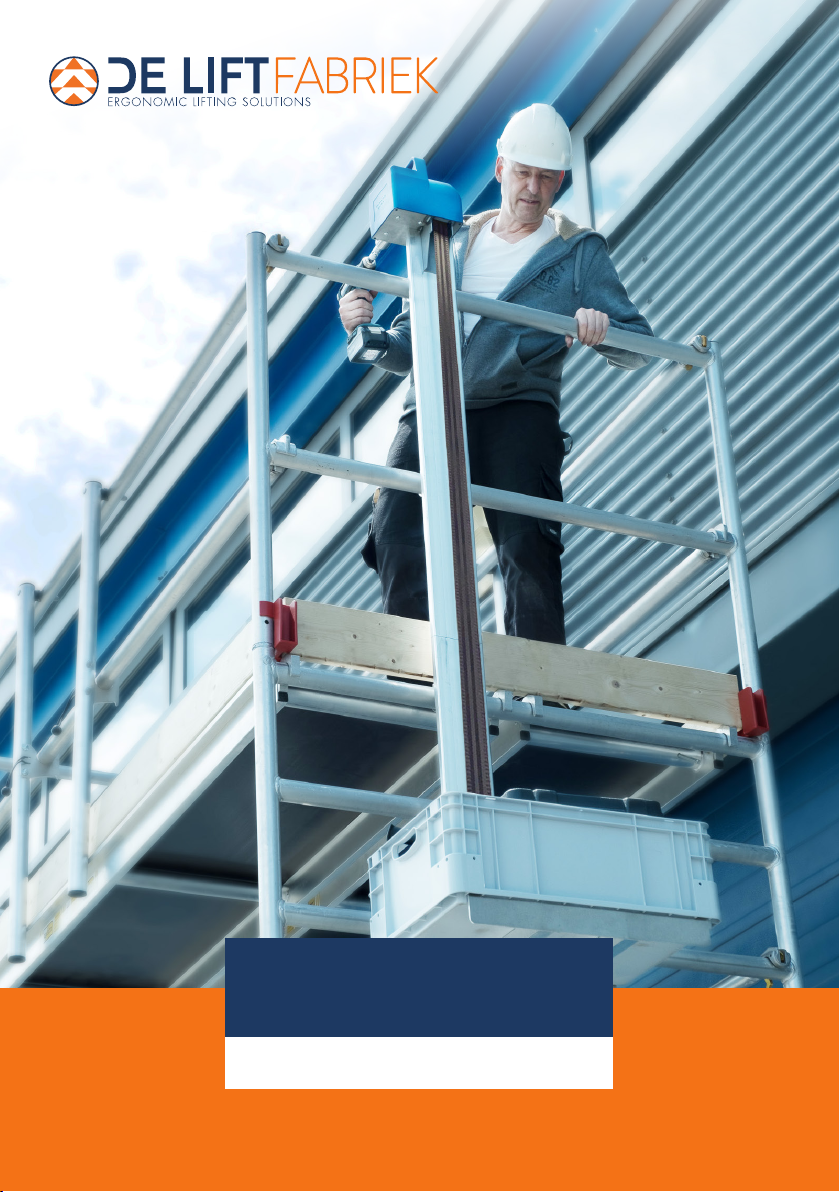
Check (i) that the outriggers are in place, (ii)
that the crate with load remains fully within
the outer diameter of the outriggers and (iii)
can move freely along the entire length of the
lift mast.
✓
✓Make sure that unauthorised persons
cannot operate the SHUTTLE. Disassemble
the SHUTTLE completely if the aforesaid
requirements cannot be (sufficiently) met.
✓Always use the slip coupling of the drill/driver
when operating the SHUTTLE winch. Set this
coupling in accordance with the instructions in
this manual.
✓Always use the SHUTTLE winch spring lock to
secure the SHUTTLE carriage at height.
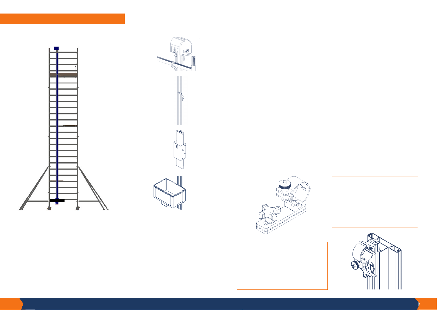
Make sure the lift mast is perfectly straight and
that the winch is completely perpendicular to
it. This is important to prevent folding of the
winch belt.
✓
DO
Do not use the SHUTTLE if there is anything
in the manual that you do not understand.
Contact the supplier for advice.
X
The SHUTTLE must never be assembled, used,
moved or disassembled by unauthorised
persons.
X
Never use the SHUTTLE in poor weather
conditions that could endanger the user (snow,
sleet, heavy rain, lightning).
X
Never use the SHUTTLE near overhead
electrical cables that are within reach of the
user.
X
X
The SHUTTLE is exclusively intended for the
vertical transport of goods and not of persons
and/or animals. Lifting and/or lowering
persons and/or animals with the SHUTTLE is
strictly forbidden.
X
Never load the SHUTTLE crate with a weight
higher than 30 kilos.
X
Never bend over the railing of the platform
to take goods out of the loading crate. The
user’s upper body must at all times remain fully
behind the platform railing.
X
Never use the SHUTTLE if the winch slip
coupling has not been properly adjusted and/
or if it is not working properly.
X
X
Never allow the SHUTTLE winch to run against
the rail end as this can damage the winch.
When using the SHUTTLE, never allow anyone
to stand or move underneath the SHUTTLE.
DON’T
3. SAFETY
DO’S/ DON’TS
Finally
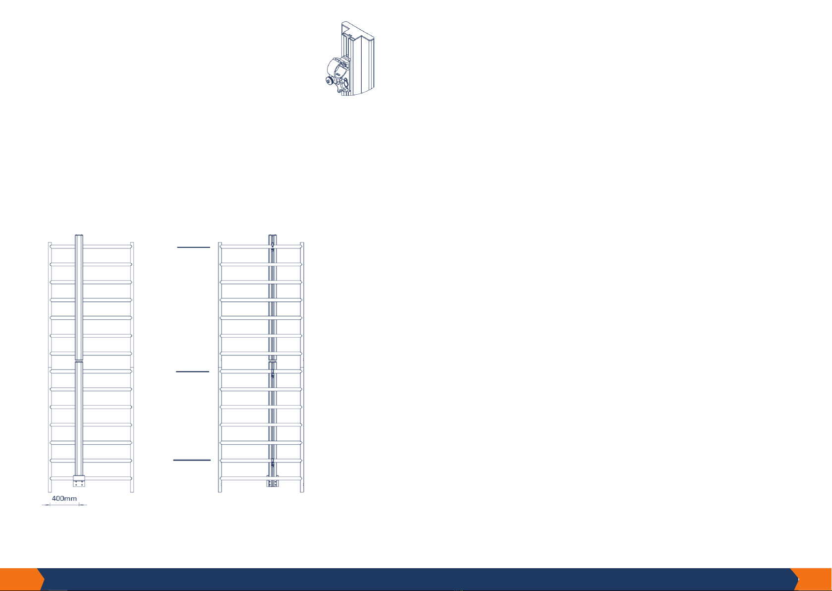
Avoid getting trapped: keep out of the way of the Shuttle.
Persons on the lower platforms of the scaolding should take care not to place their hands/
arms and feet/legs directly next to the Shuttle’s guide rail.
Likewise, make sure no objects are sticking out of the Shuttle’s path.
Warning stickers must be axed to the inside of the guide rail.
These stickers are supplied with the product by the manufacturer and more can be ordered
if desired.
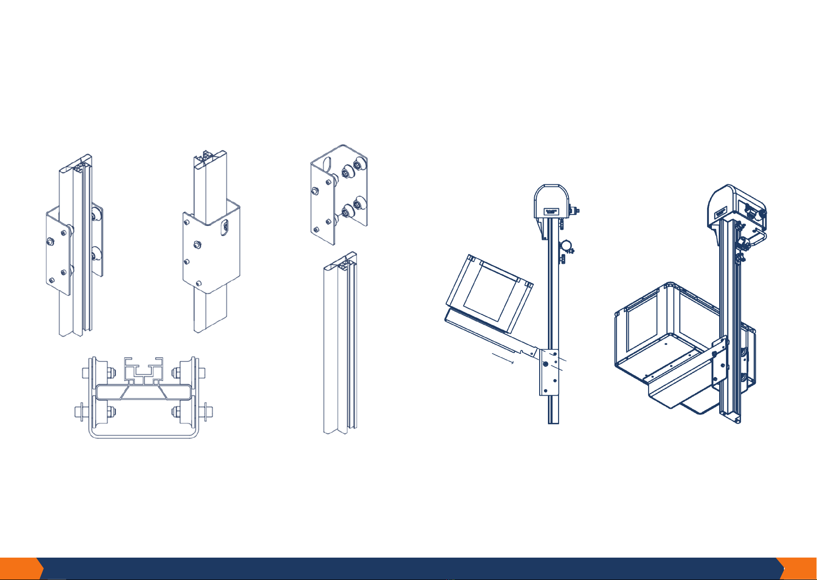
Regularly check your winch belt and make sure that it always runs perfectly flat and
straight when in operation
The most important point to pay attention to when using the winch belt is that it always
enters the winch flat and without folding and twisting. Avoid folds in the winch belt. When
entering the winch drum enters, these folds become worse and the belt no longer rolls up
flat. This will damage and weaken the winch belt.
The winch belt has enormous strength. The belt must nevertheless be checked regularly (at
least once a month) to ensure that no damage has been caused, for example, by contact
with sharp objects.
If you detect any cracks, frays or notches, replace your belt immediately!
The winch belt must be replaced with a new belt five years after its production date, due to
UV rays acting on the belt. This also applies if the belt is still completely intact.
Remember - maximum 30-kilo load and goods only
The Shuttle is designed for loads of up to 30 kilos. Do not exceed that weight. Overloading
can also damage your drill.
The Shuttle must be used to lift goods only. Under no circumstances should it be used to
lift or lower animals or children/adults.
17.
^
16.
^

4. REPAIRS AND WARRANTY
If you have a question about the SHUTTLE,
our specialists will be happy to assist and/or advise you.
Therefore, do not hesitate to contact us.
+31 (0)85 130 1956
Assembly and/or repairs
Assembly (attachment) and/or repairs are at your own expense and risk. De Liftfabriek is
not liable for damage caused by incorrect assembly and/or repairs. De Liftfabriek can be
called in to repair your product or assemble the relevant parts, at a charge.
Replacement parts
Replacement parts for the Shuttle may only be used if they have been supplied by De
Liftfabriek.
Warranty provision
The Shuttle has been designed, produced and tested with the utmost care. The following
warranty applies under the express condition that this product is used in accordance with
the instructions and its intended purpose:
1. DeLiftfabriekguaranteesthereliabilityoftheproductandthequality ofthematerial used.
2. Defects covered by the warranty will be remedied by us by replacing the defective part
or product or by sending a replacement part.
3. The following defects are, in any case, not covered by the warranty:
i. Use of the product contrary to its intended purpose or contrary to the operating
instructions.
ii. Normal wear and tear..
iii. Assembly or repairs by the customer or third parties (with the exception of fitting
parts sent as referred to under point 2 above).
iv. Changes in government regulations regarding the nature or quality of the materials
used.
4. Defects identified upon delivery must be reported to De Liftfabriek immediately. Failure
to do so will void the warranty. In order to claim under the warranty, De Liftfabriek or
your De Liftfabriek dealer requires proof of purchase.
5. Defects in the product must be reported to De Liftfabriek or your De Liftfabriek dealer as
soon as possible, but in any case, within 14 days of discovery thereof.
i. When claiming under the warranty, De Liftfabriek must be able to inspect the product in
its quality centre. The customer must make the product available for this. If the
investigation establishes that the product has been used incorrectly, investigation costs
will be charged.
ii. If the customer wishes an investigation to be conducted by an independent institute
and this investigation concludes that the product has been used incorrectly, the costs of
the investigation will be at his expense. The costs of the investigation are also payable by
the customer if De Liftfabriek has oered to repair or replace the product at its expense
prior to such an investigation.
^
19.18.
^

De Maas 22D - 5684 PL - Best (NL)
+31 (0)85 130 1956
Machine Directive
2006/42/EG
Z20-612-999-A
Table of contents
Popular Lifting System manuals by other brands

Upright
Upright SL20 Series Service & parts manual

Palax
Palax Lifter Instruction and spare parts manual

Skyjack
Skyjack SJIII 3220 Service manual

Savaria
Savaria Ceiling Lift Track Bridge owner's manual

Braun
Braun Millennium 2 AD NL Series Service manual

CarlStahl
CarlStahl CondorGrip CGUK 1.0 t operating instructions