De Lisle Amp-Speaker Selector 8x6 Pro User manual

Thank you for purchasing the de Lisle Amp-Speaker Selector 8x6 Pro! Your workflow is about to get a lot more streamlined! Please
read and understand the contents of this manual before connecting your new 8x6 Pro to any of your gear.Should you have any
questions, please contact us directly. We’re happy to help!
The exclamation point within an equilateral triangle is intended to alert the user to the presence of important operating and
maintenance (servicing) instructions in the literature accompanying the product.
1)
2)
3)
4)
5)
6)
7)
8)
9)
10)
11)
12)
13)
14)
Read these instructions.
Keep these instructions.
Heed all warnings.
Follow all instructions.
Do not use this apparatus near water.
Clean only with dry cloth.
Do not block any ventilation openings. Install in accordance with the manufacturer’s instructions.
Do not install near any heat sources such as radiators, heat registers, stoves, or other apparatus (including amplifiers) that produce heat.
Do not defeat the safety purpose of the polarized or grounding-type plug. A polarized plug has two blades with one wider than the other.
A grounding type plug has two blades and a third grounding prong. The wide blade or the third prong are provided for your safety. If the
provided plug does not fit into your outlet, consult an electrician for replacement of the obsolete outlet.
Protect the power cord from being walked on or pinched particularly at plugs, convenience receptacles and the point where they exit from
the apparatus.
Only use attachments/accessories specified by the manufacturer.
Unplug this apparatus during lightning storms or when unused for long periods of time.
Refer all servicing to qualified service personnel. Servicing is required when the apparatus has been damaged in any way, such as
power-supply cord or plug is damaged, liquid has been spilled or objects have fallen into the apparatus, the apparatus has been exposed
to rain or moisture, does not operate normally, or has been dropped.
This product should be operated only from the type of power source indicated in this manual.
SAFETY INSTRUCTIONS
WARRANTY
de Lisle Guitar Company warrants this product to be free from manufacturing defects in material and workmanship under normal use for the
life of the product. If service is required, please contact de Lisle Guitar Company directly. This warranty is void if the product has been:
a) Damaged through misuse, negligence, or abuse. b) Modified or repaired by anyone other than de Lisle Guitar Company. c) Damaged because
it is improperly connected to any other equipment.
Note: This warranty does not cover: a) Ordinary adjustments as outlined in this manual which can be performed by the customer. b) Damage to
equipment connected to the product. c) Any cost incurred in shipping the product for repair. d) Damage to the product not used in the USA.
This warranty is not transferable and only applies to the original purchase. Any implied warranties, including the warranty of merchantability, are
limited in duration to the period of this expressed warranty and no warranty whether expressed or implied shall apply to the product thereafter.
Under no circumstance shall de Lisle Guitar Company be liable for special or consequential damages arising from the use of this product, or for
any delay in the performance of this warranty due to causes beyond our control. Some states do not allow limitations on how long an implied
warranty lasts and/or do not allow the exclusion or limitation of consequential damages, so the above limitations on implied warranty and
consequential damages may not apply to you. This warranty gives you specific legal rights. You may have other rights that vary from state to
state.
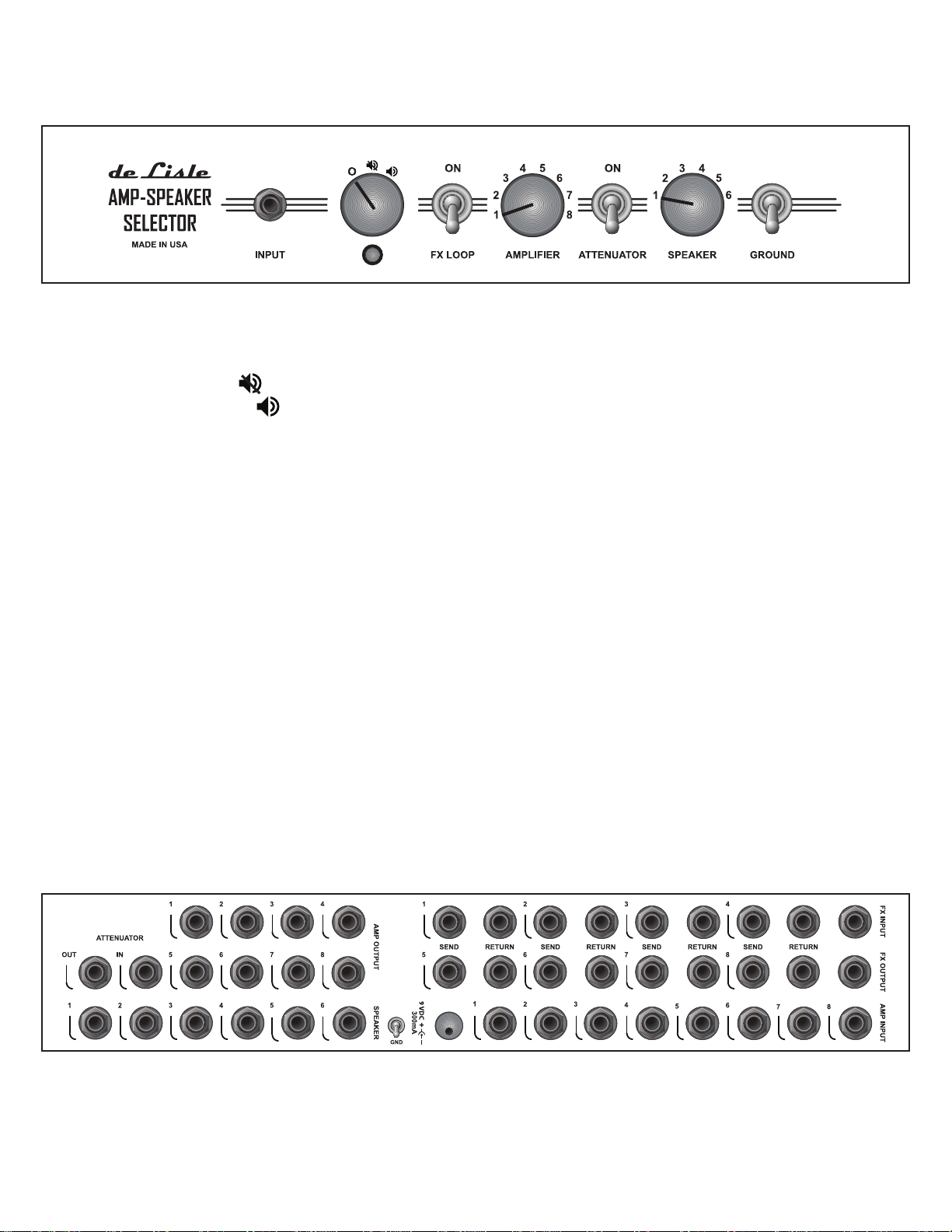
FRONT PANEL
INPUT
POWER
LED
FX LOOP
AMPLIFIER
ATTENUATOR
SPEAKER
GROUND
Connect your guitar or pedalboard output here.
The power switch has three positions. Ois off. No power is applied.Amps are muted
at their inputs, amp outputs are connected to a load and loops are put in bypass mode.
In the position, amps are muted but power is still applied to the device. In the third
position , all front panel controls are fully operational.
The LED indicator lights up when power is applied in positions 2 and 3.
If your amp is equipped with an FX loop, you can engage it by placing the switch in the
up position. This will route any FX connected to the FX INPUT and FX OUTPUT to
the corresponding Send / Return jacks on your amp. To bypass your connected FX,
place the switch in the down position.
Rotate to select the desired amplifier. The INPUT jack on the front panel will be
connected to the corresponding AMP INPUT jack on the rear panel. The AMP OUTPUT
jack will be connected to the selected SPEAKER or the ATTENUATOR if it is active. All
unused amps are muted at their inputs, switched to protection loads and their fx loops
are put in bypass mode.
Flip up to bring the connected attenuator in circuit. Use the down position to bypass
the attenuator or if no attenuator is connected to the switch. Your amps will be protected
should you not have an attenuator connected and place the switch in the active position.
Rotate to the select the desired speaker cabinet.
In most cases, this switch should be in the down position. However, should you
experience any noise that might be a grounding issue, place the switch in the up
position. For the GROUND switch to function, the amp must be connected at both the
AMP INPUT and AMP OUTPUT jacks.
REAR PANEL
ATTENUATOR IN
ATTENUATOR OUT
SPEAKER 1-6
Connect to your attenuator’s input jack (e.g. “FromAmplifier”)
Connect to your attenuator’s output jack (e.g. “To Speaker”).
Connect to your speaker cabinets.

AMP OUTPUT 1-8
GND
9V DC
AMP INPUT
Connect to the speaker output jacks of your amplifiers.
Should you experience switching noise when FX are connected to the FX INPUT
and FX OUTPUT jacks and active, find the ground position that is the quietest
with your power supply and FX. NOTE: this switch is disabled when in FX are
bypassed with the FX LOOP switch. Use the front panel GROUND switch in that
case for grounding issues.
Use only 9VDC center-negative power supplies. The switch draws between
110mA and 250mA depending on the settings. Should you hear any “whining” or
see dimming of the LED when functions are switched, the power supply is not
able to deliver enough current for the 8x6 Pro to function properly. We suggest
a 300mA or higher power supply.
Connect to the input jacks of your amplifiers. AMP INPUT 1 must be connected
to a properly ground amplifer to eliminate noise.
REAR PANEL (CONTINUED)
SPECIFICATIONS • Input Impedance: 1 Meg
• Output Impedance: 500 Ohm
• Input Sensitivity: +15 Vp-p
• Switching Time: 4-8ms
• Contact Resistance: 0.075 Ohm
• Power Consumption: 2.6W Max
• Guitar / Pedalboard Input (1)
• Amplifier Input (8)
• FX Send (8)
• FX Return (8)
• Amplifier Output (8)
• Speaker Input (6)
• Attenuator Input (1)
• Attenuator Output(1)
• Attenuator Bypass Switch
• FX Bypass Switch
• FX Input
• FX Output
• Signal Ground Switch
• Power Ground Switch
• Transformer Isolation
• Internally Isolated DC Power Supply
• Silver Relay Contacts with Gold Overlay
• Protection Loads for Unused Amplifiers
• Auto Muting of Unused Amplifiers
• Auto Bypass of Unused Amplifier FX Loops
• Premium 2U Rack Chassis with Laser Etched Panels
• 9VDC 500mA Power Supply Included (300mA Minimum Required)
• Hand-Wired
• 150W Maximum Power
• Lifetime Warranty

make or break any rear panel cable connections with the 8x6 Pro, amplifers, FX or
attenuators powered on.
use this device as a load box. Always be sure to have a proper load connected
whether it is a speaker, load box or attenuator with a built-in load.
exceed the maximum power rating of the device.
leave cables unsupported on the back of the device.
place the device near large magnetic fields such as power transformers. Doing so
may induce a voltage in the isolation transformers which will be heard as hum.
use improper cables. Be sure to use instrument cable for all AMP INPUT, FX INPUT,
FX OUTPUT, SEND and RETURN jacks. Use speaker cable for the AMP OUTPUT,
SPEAKER, ATTENUATOR IN, and ATTENUATOR OUT jacks.
DO NOT
DO NOT
DO NOT
DO NOT
DO NOT
DO NOT
PRECAUTIONS
INITIAL SETUP PROCEDURE
We recommend starting with one amp and checking your progress. With so many
cables, it can be easy to connect things incorrectly.
Be sure all devices are powered off before making any connections. Place the front
panel FX LOOP andATTENUATOR switches in the down position.
Connect a speaker cabinet to SPEAKER 1
Connect an amplifier’s speaker output toAMP OUTPUT 1.
Connect the same amplifier’s input jack toAMP INPUT 1.
If equipped, connect the same amplifier’s FX send jack to theAMP 1 SEND jack and
its FX return jack to the AMP 1 RETURN jack.
Connect the input of your pedalboard or FX unit to the FX INPUT jack and its output
to the FX OUTPUT jack. Note: FX will be bypassed while the front panel FX LOOP
switch is in the down position.
If you have an attenuator, connect its input to the ATTENUATOR INPUT jack and
its output to the ATTENUATOR OUTPUT jack. Note: the attenuator will be bypassed
while the front panel ATTENUATOR switch is in the down position.
Connect your guitar to the front panel INPUT jack. Rotate theAMPLIFIER dial to
position 1. Rotate the SPEAKER dial to position 1.
Power on the 8x6 Pro and then turn on your amplifier.
Listen for the guitar signal. If you hear it coming from the speaker, move on to 12. If
not, double check your cable connections as well as the amplifier and guitar volume
controls. Should you hear ground noise, you may need to move this amp to another
position or place the front panel GROUND switch in the up position.
To test your FX connections, place the FX LOOP switch in the up position. Should the
sound disappear, check your cable connections as well as the FX output level. Should
you hear excessive noise when switching the FX LOOP on or off, try switching the
rear panel GND switch to find the quietest position.
To test your attenuator, place the ATTENUATOR switch in the up position. Should the
sound disappear, check your cable connections as well as the attenuator output level.
Repeat the above steps as necessary to add the rest of your amps and cabinets.
1
2
3
4
5
6
7
8
9
10
11
12
13
14
Table of contents
Other De Lisle Amplifier manuals


Popular Amplifier manuals by other brands


Rockford Fosgate
Rockford Fosgate T400-2 Installation and operation

Viscount
Viscount V8.250 user manual

Link electronics
Link electronics 200 Series Mounting Frame Audio and Video DA's... Specifications

Inter-m
Inter-m AFD-6218 Operation manual

AVE
AVE VECA UTP Applications and operation manual

JUMA
JUMA PA1000 user manual