pro bel V6271 User manual

V6271
VideoMonitoring Distribution Amplifier
and DAC
UserGuide
Issue:1.0
©Pro-Bel Ltd
www.pro-bel.com

VISTEKV6271 Video Monitoring DA
&DAC
2 HU-V6271
Contents
1Description 3
2Installation 4
2.1 RearPanel Connections 4
2.2 Interfacing 4
2.3 InsertionDelay 4
2.4 Hardware 5
2.5 FrontPanel 6
2.5.1 PanelIndicators 7
2.5.2 ControlSwitches 7
2.6 Initialisation 7
3Operation 8
3.1 DefaultRate 8
3.2 625 Standard 8
3.3 525 Standard 8
3.4 NTSCStandard 8
3.5 Vertical Blanking 8
3.6 AncillaryBlanking 8
3.7 Horizontal Blanking 8
3.8 OutputsA&B 9
3.9 TestPattern 9
3.10 InScreenText 9
3.11 OutputsC, D&E 9
3.12 ComponentFormats 9
3.13 ComponentLevels 9
3.14 Feature1 9
3.15 Feature2 9
3.16 Feature3 10
4DACCalibration 11
4.1 Proceedure 11

VISTEKV6271 Video Monitoring DA
&DAC
Issue 1.0 3
1 Description
The V6271 isaSerialDigitalVideo Distribution Amplifierwithconverterstoanalague
compositeand componentsignals,whichformspartofthe VistekV1600 range ofinterface
products.It isa3U high card,whichisfitted intoeitheraV1601,V1603 orV1606 rack,from
whichitgetsitspowerand remotecontrol.The modulecan alsobe housed inthe 1-Boxor2-
Box.Apassiverearmodule, 16VR1Bor16VR3B, isrequired forall signalinterconnections.
The unitisfullydualstandardforboth625/50 and 525/60 D1 signals.It can automatically
detectthe inputstandardand operateaccordingly,and itisalsoforced intoastandardwhen
thereisno input.
The unit can producethe analogue compositeand component signalsinvariousformats.
The formatsare: -
Composite
PAL, PALN, PALM, NTSC, NTSC-Japan
Component
YC (standardlevels, BetalevelsorUSMII levels), withorwithout set-up
Y, Pb, Pr (standardlevels, BetalevelsorUSMII levels), withorwithout set-up
GBR withorwithout set-up
Aninternaltestpatterngeneratorisalsoincluded foralignmentpurposes,producing either
ColourBarsorPluge.
Incommon withall VistekV1600 modularunitsthereislocalcontrol,whichletsthe user
adjustall ofthe controls.Inaddition the modulemaybe controlled remotelyusing the DART
system.DARTisthe generalpurposecontrolarchitecturesupplied byVistekand other
manufacturers, and enablesfull controland monitoring ofthisand all otherV1600 units.
The frontpanelshowsthe statusofthe modulesoutputsand alsohasthe TestPatternon/off
switch,whichoperateswhen inlocalmode.All otherlocalcontrolsarelocated on switches
behind the frontpanelon the module.Local/Remotemode isalsoselected fromaswitchon
the front panel.
VISTEKV6271 Video Monitoring DA
&DAC
4 HU-V6271
2 Installation
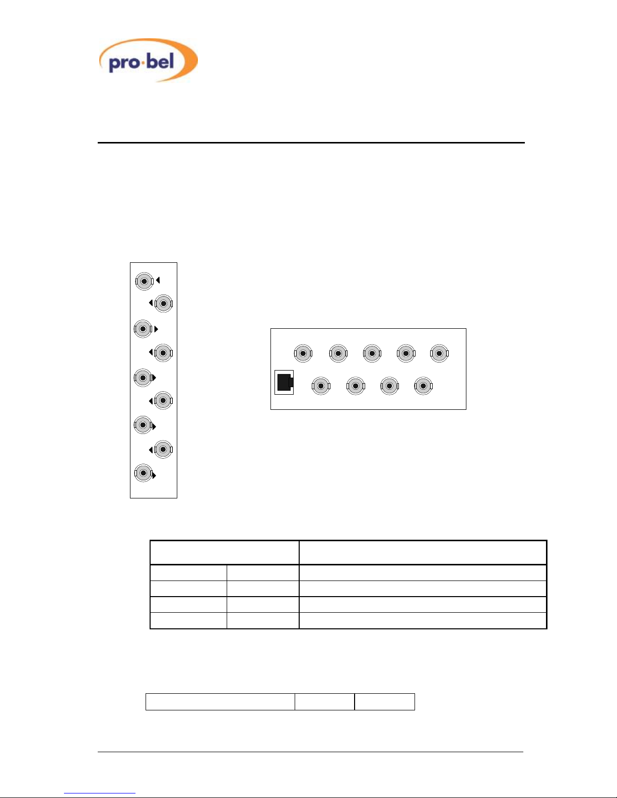
2.1 RearPanel Connections
The V6271 rearmoduleconnectionsareshownbelow.
3U RearModule(16VR3B)1U RearModule(16VR1B)
2.2 Interfacing
SIGNAL COMMENTS
Power ~3.5W Supplied fromrack
SDI I/PBNC Video toSMPTE259M. Receivecablelengthup to200m
SDI O/P1-4 BNC Video toSMPTE259M. Drivecablelengthup to200m
Outputs BNC Compositeand ComponentAnalogue Video Standards
2.3 Insertion Delay
SDI Input toAnalogue outputs 2.5 ms
SDI 1
SDI 2
DART
SDI
I/P
SDI
O/P
SDI 1
O/P
SDI 2
O/P
SDI 3
O/P
CVBS/Y
SDI 3
SDI 4
CVBS
Y
CVBS
C
CVBS
Pb/B
CVBS
Y/G
CVBS
Pr/R
O/P
CVBS/C
O/P
CVBS/Y/G
O/P
CVBS/Pb/B
O/P
CVBS/Pr/R

VISTEKV6271 Video Monitoring DA
&DAC
Issue 1.0 5
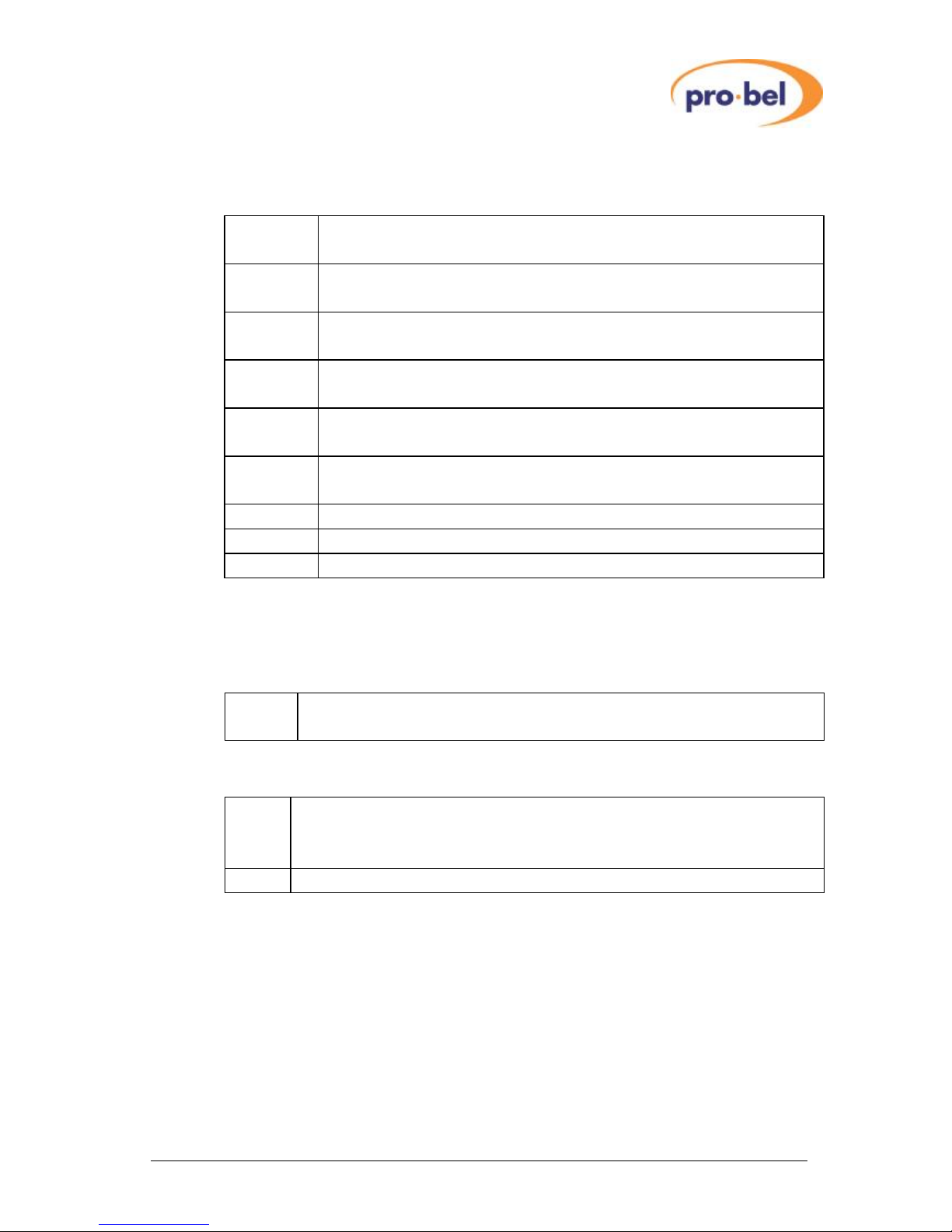
2.4 Hardware
The figurebelowshowsdiagrammaticallythe printed circuitboardalong withcertainother
componentsofinterest. Inparticularitshowsthe position and orientation ofthe controlsand
switches, whichset up Outputswhen operated inLocalcontrol
The purposesofthe controlswitchesareshowninthe following table
Switch1 Title LeftPosition (Default) RightPosition
SW1-1 Default Rate 625 Lines 525 Lines
SW1-2 625 Standard PAL PalN
SW1-3 525 Standard NTSC PALM
SW1-4 NTSCStandard NTSC NTSC–Japan
SW1-5 VerticalBlanking Pass Blank
SW1-6 Ancillary Blanking AlwaysBlanked
SW1-7 HorizontalBlanking Narrow Wide
SW1-8 OutputsA&B CVBS YC
Switch 2 Title LeftPosition (Default) RightPosition
SW2-1 Test Pattern Pluge ColourBars
SW2-2 InScreen Text On Off
SW2-3 OutputsC, D&E CVBS Component
SW2-4 Component Format Y, Pb, Pr GBR
SW2-5 Component Levels N10 Beta
SW2-6 Feature1 Black detect ON Black detect Off
SW2-7 Feature2 AudioGroupsdisplayOn AudioGroup displayOff
SW2-8 Feature3 Reserved -
Front Panel
Rear Connector
SW1SW2
PL1
PL2

VISTEKV6271 Video Monitoring DA
&DAC
6 HU-V6271
2.5 FrontPanel
The front panelshownabovehasthree purposes:
Provide the userwithindication ofthe operating conditions
OfferLocalcontrolofTest Signal
Select the controlsource
REM +V
Local
Rem
V6271
Monitoring
DAC
RemoteControl AccessandPower indicators
Input SignalFormat
REMOTE/LOCALcontrolselection
NTSC
PALM
PALI
PALN
TestSignal
ONOFF
LocalSelection &GlobalIndication of Test Pattern
YC
Analogue OutputType(CVBSor YC, YUV/GBR) (amber)
YUV/
GBR
VISTEKV6271 Video Monitoring DA
&DAC
Issue 1.0 7
2.5.1 Panel Indicators
The LEDson the panelhavethesemeanings
REM Shortblinkstoindicateaccess bythe DARTcontroller,iffitted.It does not
indicatethat the unit isinone ofitsremotecontrolmodes.
+V Indicatesthat5Vispresenton the board.Thisisderived fromthe +15V
distributed through the rack.
PALI Indicatesthata625/50 YC,YUV,GBRand/orPALIformatsignalisbeing
Output.
PALN Indicatesthata625/50 YC,YUV,GBRand/orPALNformatsignalisbeing
Output.
PALM Indicatesthata525/60 YC,YUV,GBRand/orPALMformatsignalisbeing
Output.
NTSC Indicatesthata525/60 YC,YUV,GBRand/orNTSCorNTSC-Japan format
signalisbeing Output.
YC Indicatesthat aYCformat signalisbeing Output on OutputsA&B.
YUV/ GBR Indicatesthat aYUVorGBRformat signalisbeing Output on OutputsC,D&E.
Test Signal Indicatesthat the Test Signalhasbeen switched on.
Note:Aflashing standardLEDindicatesthat thereisno input.
2.5.2 Control Switches
The upperswitchhastwopositionsand selectsthe Test Patternwhen inLocalControlMode:
Off/ On Switcheson the InternalTestPattern,ColourBarsorPluge,when the unitis
operating inLocalMode. (Hasno effect inRemoteMode)
The lowerswitchhastwopositionsand selectsthe controlsource:
Rem Controlisfromthe DARTsystem.Thisrequiresthe useofan externalcontroller
running asuitableprogramme,whichcommunicateswithmultipleracksusing the
Dartnet protocol.
Local Controlisfromthe front panelitself.
2.6 Initialisation
When the unitpowersup itwill be setitselftothe conditionsassetbythe localcontrol
switches,butwill updatetothe Remotecontrolsettingsif enabled and present. Inthe Remote
controlmode anychangeswill be made bythe controlsystem,butinLocalcontrolmode they
will be made on the switchesbehind the front panel.

VISTEKV6271 Video Monitoring DA
&DAC
8 HU-V6271
3 Operation
3.1 DefaultRate
Thisselection determinesthe defaultline ratewhen no inputispresent. If thereisan inputthe
moduleoutputswill switchtothe input line rateand standarddefined below.
3.2 625 Standard
When thereisno input and the default rateisset to625 orthereisa625 line ratesignalon the
input, thisswitchwill determine the output standardofthe compositesignals.
3.3 525 Standard
When thereisno input and the default rateisset to525 orthereisa525 line ratesignalon the
input, thisswitchwill determine the output standardofthe compositesignals.
3.4 NTSCStandard
The NTSCstandardisselected bythiscontroltobe eithernormalNTSCorthe Japanese
format ofNTSCwithout pedestal.
3.5 Vertical Blanking
The VerticalBlanking controlwill removeall dataduring the verticalinterval,suchasWide
Screen signalling and VerticalIntervalTest signals.
3.6 AncillaryBlanking
The Ancillary Blanking hasno effect, asthe outputsarealwaysblanked horizontally.
3.7 Horizontal Blanking
The HorizontalBlanking controlselectsthe widthofthe blanking toeitherdigitalvideo or
analogue video standards.

VISTEKV6271 Video Monitoring DA
&DAC
Issue 1.0 9
3.8 Outputs A&B
The outputsA&Bcan be selcted tobe eithercompositevideo orYCcomponents
3.9 Test Pattern
The internalTestpatterncan be selected between Pluge (formonitoralignment)and Colour
Bars.
3.10 InScreenText
The InScreen Textcan be selected toprovide indication withinthe outputactivepicturearea,
ofthe inputSDIvideo status.Thisisusefulasthe modulewill provide avalidoutputpicture
even withno input, thereforethe InScreen Textwill indicateI/PFailed.Using the Feature
switchesthe input at Black and AudioGroupscan alsobe displayed.
3.11 Outputs C, D&E
The outputsC,D&Ecan be selcted tobe eithercompositevideo orYPbPr/GBRcomponent
video.
3.12 ComponentFormats
Thiscontrolwill selectthe formatofthe C,D&Eoutputstobe eitherY,Pb,Pr orG,B,R,
when theyareoperating incomponent mode.
3.13 ComponentLevels
The levelsofthe componentsignalscan be settobe eitherN10 (standardLevels)orBeta
Levels.
3.14 Feature1
Feature1enablesthe displayofinscreen textwhen the inputsignalhasbeen atblack for
about 10 seconds.The InScreen Text selection must alsobe on.
3.15 Feature2
Feature1enablesthe displayofinscreen textofthe Embedded audiogroupson the input
signal.The InScreen Text selection must alsobe on.

VISTEKV6271 Video Monitoring DA
&DAC
10 HU-V6271
3.16 Feature3
Reserved.

VISTEKV6271 Video Monitoring DA
&DAC
Issue 1.0 11
4 DAC Calibration
The V6271 hastwocalibrations,one controlsthe CVBS,Y,Coutputsand the othercontrols
the Y, Pb, Pr, G, B, Routputs.
When incalibration mode the outputsareautomaticallyselected toCVBS and Y,Pb,Pr and
onlythe CVBS/Y(orthe CVBS/Con aV6271/4)and Y/G outputsneed tobe monitored for
adjustment.
4.1 Proceedure
Connectashorting linktoPL1.(Thiswill setthe outputstoCVBS,Y,Pr,Pband selectthe
internalcolourbartest signal.)
Monitorone ofthe CVBS channels.
Set SW2switch1off
2on
3on
4off
Set SW1switchestoobtain1Vp-pbetween syncbottomand whitebar.
ToggleSW2switch4on and offtwicetostorevalue inProm.
Monitorthe Youtput ofthe Y,Pb,Pr channels.
Set SW2switch1on
2off
3on
4off
Set SW1switchestoobtain1Vp-pbetween syncbottomand whitebar.
ToggleSW2switch4on and offtwicetostorevalue inProm.
Removethe linkon PL1 and connect toPL2 momentarilytoreset the module.
Returnall switchestooffexceptSW2switch1,2&3whichshouldbe on.Selectthe test
patterngeneratorand check the twoYchanneloutputlevels,toensurethe calibration values
havebeen stored inthe PROM.
Table of contents
Other pro bel Amplifier manuals


