De Nora Capital Controls CHLORALERT T17CA4000 Series User manual
- 1 - 325.6030.7
Instruction Manual
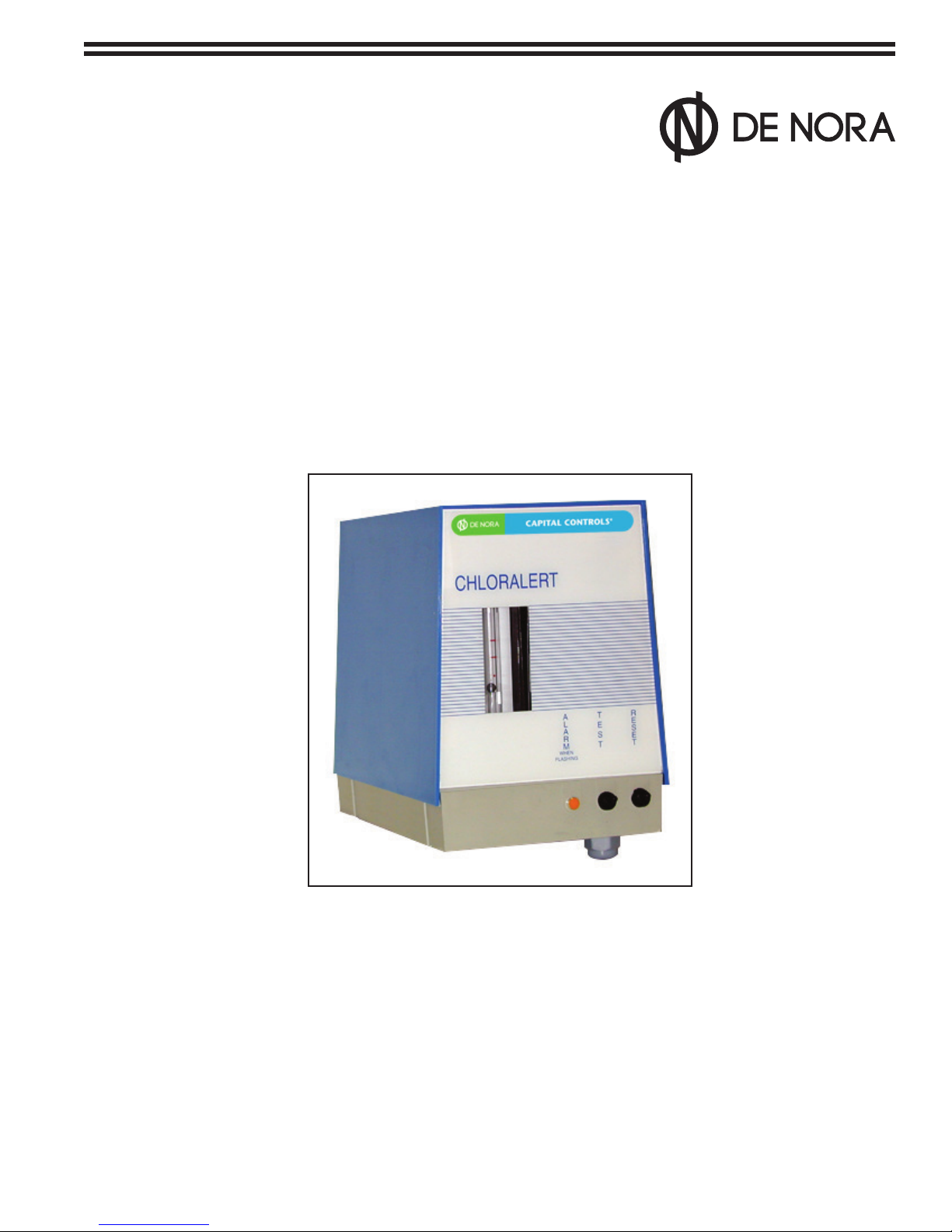
CHLORALERTTM
Series T17CA4000
Chlorine Gas Leak Detector CAPITAL CONTROLS®

325.6030.7 - 2 -
These instructions describe the installation, operation and maintenance of the subject equipment. Failure to strictly
follow these instructions can lead to an equipment rupture that may cause signicant property damage, severe
personal injury and even death. If you do not understand these instructions, please call De Nora Water Technologies
for clarication before commencing any work at +1 215-997-4000 and ask for a Field Service Manager. De Nora Water
Technologies, Inc. reserves the rights to make engineering renements that may not be described herein. It is the
responsibility of the installer to contact De Nora Water Technologies, Inc. for information that cannot be answered specically
by these instructions.
Any customer request to alter or reduce the design safeguards incorporated into De Nora Water Technologies
equipment is conditioned on the customer absolving De Nora Water Technologies from any consequences of such a
decision.
De Nora Water Technologies has developed the recommended installation, operating and maintenance procedures with
careful attention to safety. In addition to instruction/operating manuals, all instructions given on labels or attached tags
should be followed. Regardless of these eorts, it is not possible to eliminate all hazards from the equipment or foresee every
possible hazard that may occur. It is the responsibility of the installer to ensure that the recommended installation instructions
are followed. It is the responsibility of the user to ensure that the recommended operating and maintenance instructions are
followed. De Nora Water Technologies, Inc. cannot be responsible deviations from the recommended instructions that may
result in a hazardous or unsafe condition.
De Nora Water Technologies, Inc. cannot be responsible for the overall system design of which our equipment may be
an integral part of or any unauthorized modications to the equipment made by any party other that De Nora Water
Technologies, Inc.
De Nora Water Technologies, Inc. takes all reasonable precautions in packaging the equipment to prevent shipping damage.
Carefully inspect each item and report damages immediately to the shipping agent involved for equipment shipped“F.O.B.
Colmar” or to De Nora Water Technologies for equipment shipped“F.O.B Jobsite”. Do not install damaged equipment.
De Nora Water Technologies, Colmar Operations
Colmar, Pennsylvania, USA
is ISO 9001: 2008 Certied
READ THE ENTIRE MANUAL BEFORE OPERATING
USE ONLY IN ACCORDANCE WITH INSTRUCTION MANUAL
WARNING: HAZARDOUS VOLTAGES

- 3 - 325.6030.7
INSTRUCTION BULLETIN
CHLORINE GAS LEAK DETECTOR
"CHLORALERT"
Model T17CA4000
Rev. 1.2
IMPORTANT
The instructions given herein cover generally the description, installation, operation and maintenance of subject
equipment.
DNWT reserves the right to make engineering renements that may not be reected in this Bulletin.
Should any question arise which may not be answered specically by these instructions, they should be directed to
De Nora Water Technologies for further detailed information and technical assistance.
DNWT takes all possible precautions in packing each equipment item to prevent damage during shipment.
Carefully inspect each item and if damage has occurred report it immediately.
Do not install any equipment if damage is such that faulty operation is likely to result.
If plant engineering drawing are available at the installation site , locate, mount , pipe and wire thesubject equipment
in accordance with these drawings.
If plant engineering drawings are not available, refer to the Installation section for information concerning these
requirements.
Carefully inspect all packing material before discarding it to prevent loss of mounting hardware, accessories, spare
parts or instructions.
All instructions given on any attached tag should be followed.
WARNING
To assure safe operation this equipment carefully follow use and installation instructions
and recommendations illustrated in this Manual. Improper use of the equipment
may damage the equipment and endanger the safety
of the operating personnel.

325.6030.7 - 4 -
PAGE INTENTIONALLY LEFT BLANK

- 5 - 325.6030.7
TABLE OF CONTENTS
1 INTRODUCTION ............................................................................................................................................................ 6
1.1 General Description ............................................................................................................................................................................. 6
2 TECHNICAL SPECIFICATIONS ....................................................................................................................................... 7
3 MODEL NUMBER BREAKDOWN ................................................................................................................................... 9
3.1 Standard accessories............................................................................................................................................................................ 9
4 INSTALLATION .......................................................................................................................................................... 10
4.1 Location ..................................................................................................................................................................................................10
4.2 Mounting................................................................................................................................................................................................10
4.3 Sampling line ........................................................................................................................................................................................11
4.4 Electrical wiring....................................................................................................................................................................................11
5 OPERATION, MAINTENANCE AND TESTING.............................................................................................................. 12
5.1 Electrolyte lling at start up ............................................................................................................................................................12
5.2 Electrolyte renewal after operation .............................................................................................................................................12
5.3 Sample ow rate..................................................................................................................................................................................12
5.4 Gas Test 12
5.5 Circuit performance check...............................................................................................................................................................13
6 MAINTENANCE PROCEDURES.................................................................................................................................... 14
6.1 Measuring cell maintenance...........................................................................................................................................................14
6.2 Flowmeter ..............................................................................................................................................................................................14
6.2.1 For Model T17CA4100 ......................................................................................................................................................14
6.2.1 For Model T17CA4200 ......................................................................................................................................................14
6.3 Electronic circuit board .....................................................................................................................................................................14
6.4 Optical sensor (Only for Model T17CA4200)..............................................................................................................................14
7 CE DECLARATION........................................................................................................................................................ 15
FIGURES
1 CHLORALERT Internal View................................................................................................................................................................ 4
2 Outline Dimensions.............................................................................................................................................................................. 8
3 Typical Installation ..............................................................................................................................................................................10
4 Electrical Wiring....................................................................................................................................................................................11

325.6030.7 - 6 -
1 INTRODUCTION
1.1 General Description
The De Nora Water Technologies chlorine gas leak detector, CHLORALERT™ T17CA4000, continually monitors air
samples for the presence of chlorine. It is usually installed in chlorine usage and storage areas to protect personnel
and equipment.
A small internal air blower continually draws a sample of air into the Chloralert. The owmeter and valve enable a
xed amount of air to be passed over the surface of the special electrolyte, where the chemical reaction takes place
in presence of chlorine. Two platinum electrodes, half immersed in the electrolyte, pick up the electrochemical
current thus generated which is measured by the electronic circuit and used to trigger an alarm system.
The trip point may be factory set to 1 or 3 ppm chlorine in air by volume. The power on/alarm lamp commences
ashing in the alarm condition.
In the Model T17CA4100, a relay is also energized to enable external alarms, extractor fans etc. to be activated. The
alarm condition is generated, in addition to the presence of chlorine in air, also by power failures, when the power is
returned to the system.
In the Model T17CA4200, a relay is also de-energized to enable external alarms, extractor fans etc. to be activated.
The electrical circuits are designed such that power supply failure causes the alarm relay to go into the alarm state.
A ow sensor detects when there is no sample ow and causes the alarm relay to go into the alarm state. The
sample fan is stopped when the alarm condition is actuated, to prevent saturation of electrolyte with chlorine and
contaminated air to be discharged in safe area through the Chloralert™ itself.
The unit has an integral electrical test facility.
The alarm needs operator's acknowledgment to be reset.
Figure 1 - CHLORALERT Internal View

- 7 - 325.6030.7
2 TECHNICAL SPECIFICATIONS
Power supply: 120 Vac, 60 Hz
220 Vac, 50 Hz
110 Vac, 50 Hz
Detection level: 1 ppm (3 mg/m3), or 3 ppm (9 mg/m3)
Relay contacts: DPDT, 10 A. 240 Vac, resistive load or 28 Vdc
Cell response time: Instantaneous
Warm up time: Max 3 minutes
Sampling rate: 0.05 m3/min
Ambient temperature: -20°C (-4°F) to +65 °C (149°F)
Sample inlet connection: 1" NPT
Weight: approx. 2.8 kg
Mounting: Wall
Dimensions: 215 H x 162 W x 235 D (mm)
Material of construction: Housing: ABS
Cell: ABS
Electrodes: Platinum

325.6030.7 - 8 -
Figure 2 - Mounting and Outline Dimensions in inches (mm)
CHLORALERT
R
E
S
E
T
A
L
A
R
M
T
S
T
E
WHEN
FLASHING
C
C
NREVES
SERVICES
TR N
E T

- 9 - 325.6030.7
3 MODEL NUMBER BREAKDOWN
T17CA4 B
Basic CHLORALERT™
Alarm Design
1 - Standard
2 - Fail Safe
Electrical Requirement
10 - 120 Vac, 60 Hz
20 - 220 Vac, 50 Hz
30 - 110 Vac, 50 Hz
Design Level
Alarm Level
3 - 1 ppm, Fixed
4 - 3 ppm, Fixed
3.1 Standard accessories
1 kit P/N 614S071U0l including:
• 1 electrolyte bottle
• 1 spare oat
• 1 set of spare O-Ring
• 1 insect screen

325.6030.7 - 10 -
4 INSTALLATION
4.1 Location
The Chloralert™ should ideally be mounted outside the area to be monitored. However it can be mounted in the
contaminated area if it is considered absolutely necessary. The location should be such that the ambient temperature
never falls below -20 °C (-4°F) nor rises above 65 °C (149°F).
It should never be mounted in direct sunlight and should be protected from the weather if mounted outside.
4.2 Mounting
Securely mount the Chloralert™ at a convenient working height (approx. 1,3 - 1.5 m from the oor).
4.3 Sampling line
As the Chlorine weight is higher then the air, we recommend that the sample inlet point is located at
about 200 mm (8") from the oor. Use of frigid or exible 1” PVC tubing is recommended. It is
recommended to install the proper insect screen (supplied) at the terminal point of the sample line to
avoid dust suction.
WARNING
NEVER USE TUBES WITH A DIAMETER LOWER THAN 1" WHEN
THE SAMPLE PIPE LENGTH EXCEEDS 4 M
Figure 3 - Typical Installation
CHLORALERT
R
E
S
E
T
A
L
A
R
M
T
S
T
E
WHEN
FLASHING
C
C
NREVES
SERVICES
T R N
ET

- 11 - 325.6030.7
4.4 Electrical wiring
Cable gland on the Chloralert™ will accept a cable of diameter between 5 to 10 mm. Refer to the following drawings
to connect the power supply and the external signals to the Chloralert.
Figure 4 - Electrical Wiring

325.6030.7 - 12 -
5 START-UP, OPERATION AND MAINTENANCE
5.1 Electrolyte lling at start up
Refer to gure 5.
Switch o power supply or unplug instrument.
Remove cover rising it.
Disconnect cell cable from terminal block noting carefully position of each cable.
Disconnect exhaust tubing from the cell.
Unscrew the four retaining screws and drop bottom half of cell from the upper for lling.
The electrolyte bottle contains a dropper. Fill dropper stem to mark 1ml- Carefully transfer electrolyte from dropper
to cell, taking care not to allow it to touch the top surface of the cell.
Remove any electrolyte on this surface with a tissue then reassemble cell together taking care not to tilt the
bottom half too much.
Reassemble exhaust tubing, reconnect the cell cable, replace lid and nally reconnect supply cable and switch on.
Hold RESET switch down until alarm lamp ceases to ash then wait further 5-10 sec. before releasing
switch (this operation can take up to 3 minutes.)
The unit is now in operation.
5.2 Electrolyte renewal after operation
Approximately once a year or as necessary the electrolyte should be renewed.
Proceed as for start up but wash the electrolyte thoroughly from the cell with water and gently clean the
electrode faces with a non abrasive chlorine-free cleaner.
Again thoroughly wash cell with water, dry with a clean tissue and rell with electrolyte as described under
Section 5.1.
5.3 Sample ow rate
At start up set the sample ow so that the ow indicator sits between the two graduation marks on the
owmeter tube.
The ow may be adjusted by inserting a broad bladed screwdriver in the rate valve and gently twisting until the oat
is properly positioned.
This should be done with the air control knob in the wide open position.
If the required cell ow cannot be obtained, the air control knob should be gradually closed, until the
adjustment of the oat position is possible.
The position of the oat in the owmeter tube should be checked from day to day (during the rst week) and
adjusted if necessary.
5.4 Gas test
Verify the instrument operation in presence of chlorine gas after the start up.
The test suggested hereafter is only qualitative and can be performed using solutions commonly available such as
bleach and vinegar.
Mix 6 parts of bleach and one part of vinegar in a beaker.
Place the beaker under the sampling fan. The alarm LED should start ashing and any remote device connected to
the alarm relay should be actuated.
The alarm is reset by pressing RESET switch till the alarm LED stops ashing
(this operation may require up to 3 minutes).

- 13 - 325.6030.7
5.5 Circuit performance check
Simultaneously press and hold down both TEST and RESET switches. The alarm LED must change
from the steady condition to ashing and the sampling fan stays activated.
This checks that the electronic circuits are operating properly.
If it is desired to check external circuits the RESET switch must be released: any remote device
connected to the relay will be actuated.
If it is required that external devices are not actuated during this test, release the TEST switch rst wait for the LED to
assume a steady state, (this operation may require up to 3 minutes), then release the RESET switch.

325.6030.7 - 14 -
6 MAINTENANCE PROCEDURES
Note: disconnect power supply before removing the instrument cover.
6.1 Measuring cell maintenance
Refer to Section 5.1 and 5.2 of this manual.
6.2 Flowmeter
6.2.1 For Model T17CA4100
Clean tube and oat whenever dirt has accumulated causing malfunction.
Using a screwdriver loosen and slide the top tube retainer ring towards the enter of the tube.
Remove tube by pulling forward.
WARNING
TAKE CARE NOT TO LOSE THE ORING AND THE FLOATS!
Clean all parts in mild detergent, rinse and wipe dry using clean tissue paper.
To reassemble, place the tube retainer ring over the tube, replace the O-ring, drop the oat
in the tube and re-position tube between inlet and outlet connections.
Gently slide the tube retainer ring back into position, making sure it is properly located by
carefully rotating (red mark on the tube should be on the front side).
6.2.2 For Model T17CA4200
Clean tube and oat whenever dirt has accumulated causing malfunction.
Remove the plastic ow tube retainer by unclipping from the ow tube.
Using a screwdriver loosen and slide the top tube retainer ring towards the enter of the tube,
also lift the optical sensor housing towards the center of the tube.
Remove tube by pulling forward.
WARNING
TAKE CARE NOT TO LOSE THE ORING AND THE FLOATS!
Clean all parts in mild detergent, rinse and wipe dry using clean tissue paper.
To reassemble, place the tube retainer ring and optical sensor over the tube, replace the O-ring, drop the
oat in the tube and re-position tube between inlet and outlet connections.
Gently slide the tube retainer ring and sensor housing back into position, making sure they are properly
located by carefully rotating (red mark on the tube should be on the front side).
6.3 Electronic circuit board
It is recommended that in the event of failure of the electronic board a replacement is tted and the
faulty board is returned to factory for repair.
6.4 Optical sensor (Only for Mod. T17CA4200)
The ow sensor is housed in a heat shrunk sleeve. For this reason it is recommended that the faulty
unit is replaced with a spare item.

- 15 - 325.6030.7
7 CE DECLARATION
Chlorine Gas Leak Detector Model T17CA4000 is in conformity with the following standards:
• EN 56681-2 (Generic emission standard, industrial environment)
• EN 56682-2 (Generic emission standard, industrial environment)
Following the provisions of directives:
“Electromagnetic compatibility 89/336/CEE, modied by directive 92/31/CEE".

325.6030.7 - 16 -
Represented by:
Design improvements may be made without notice.
DEC 2018
De Nora Water Technologies
3000 Advance Lane Colmar, PA 18915
ph +1 215 997 4000 • fax +1 215 997 4062
web: www.denora.com
mail: info[email protected]
®Registered Trademark. © 2018. All Rights Reserved.
Table of contents
Other De Nora Gas Detector manuals

Popular Gas Detector manuals by other brands

IGD
IGD 2-Wire Systems Installer's guide

Honeywell
Honeywell Searchpoint Optima Plus Safety manual

Mircom
Mircom CO1224T quick start guide

Herth+Buss
Herth+Buss ELPARTS SelectH2 mini operating instructions

Control Equipment
Control Equipment GX-3R Quick reference guide

yellow jacket
yellow jacket 69310 instructions


Riken Keiki
Riken Keiki SD-1DRI operating manual

Helios
Helios KWL-VOC eC Installation and operating instructions

Bellman & Symfon
Bellman & Symfon BE1555 manual

Adicos
Adicos GSME-X22 Supplementary instructions manual

United Electric Controls
United Electric Controls Vanguard Installation and maintenance instructions

MSA
MSA ALTAIR4 Quick start card