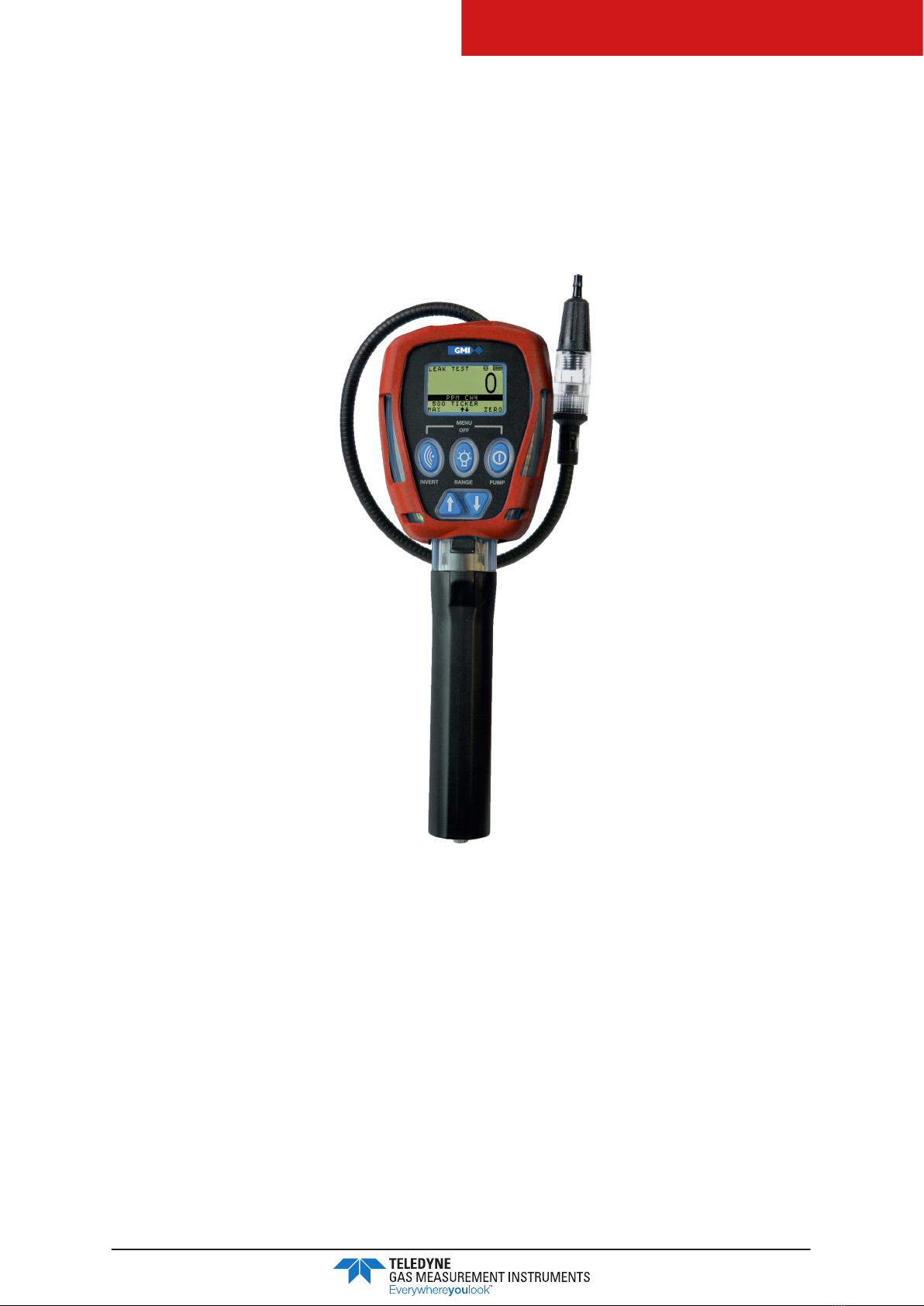
Teledyne Everywhereyoulook GT-FIRE User manual

User Manual
67816 Revision D
GT-FIRE
PORTABLE GAS DETECTOR

GT-FIRE
PORTABLE GAS DETECTOR
67816
Revision D
2
WARNING: ALL INDIVIDUALS WHO HAVE, OR WILL HAVE,
RESPONSIBILITY FOR USING, MAINTAINING, OR SERVICING THIS
PRODUCT MUST READ THIS ENTIRE MANUAL CAREFULLY. FAILURE TO
USE THIS EQUIPMENT PROPERLY COULD RESULT IN SERIOUS INJURY
OR DEATH.
LEGAL STATEMENT
Teledyne, the Teledyne Logo, Gas Measurement Instruments, GMI and GT-Fire are registered
and/or unregistered marks of Teledyne Gas Measurement Instruments Ltd, also referred to as “the
Company.”
All rights reserved. No part of this documentation may be reproduced in any form or by any means
or used to make any derivative work (such as translation, transformation, or adaptation) without
written permission from the Company.
Microsoft, Windows, Windows 2000, Windows Me, Windows XP, Windows NT, Windows
Vista, Windows 7, Internet Explorer and MS-DOS are either trademarks or registered trademarks
of Microsoft Corporation in the United States and other countries. Solaris and JAVA are either
trademarks or registered trademarks of Sun Microsystems, Inc. All other products or service names
are the property of their respective owners.
DESCRIPTION
This User Guide provides information for use only with the GT-Fire Portable Gas Monitor (or “the
monitor”).
LIABILITY
Every care has been taken in the preparation of this user guide, but the Company does not accept
any responsibility for errors or omissions and their consequences. Information in this user guide is
subject to change without notice. This user guide does not constitute a specification or basis for a
contract.
MODIFICATION NOTICES
The Company aims to notify customers of relevant changes in the product operation and maintain
this user guide up to date. Due to continuous product improvement, there may be operational
differences between the latest product and this user guide.
This user guide is an important part of the monitor, and it should be referred to for the life of the
product.
SOFTWARE
Any software supplied must only be used in this product and may not be copied without the written
permission of the Company. Reproduction or disassembly of such embodied programs or algorithms
is prohibited. Ownership of such software is not transferable, and the Company does not warrant
that the operation of the software will be error free or that the software will meet the customer’s
requirements.

GT-FIRE
PORTABLE GAS DETECTOR
67816
Revision D
3
DISPOSAL ADVICE
Dispose of the monitor carefully and with respect for the environment. If returned, the Company will
dispose of the monitor without charge.
AREAS OF USE
Exposure to certain chemicals can result in a loss of sensitivity of the flammable sensor. Where such
environments are known or suspected, it is recommended that more frequent response checks are
carried out.
Environmental factors may affect sensor readings. This includes changes in pressure, humidity and
temperature. Note that both pressure and humidity changes can also affect the amount of oxygen
present in the atmosphere.
Exposure to silicones, high levels of H2S and other sulfur-containing compounds, phosphates, and
refrigerant gases (Freon) may contaminate, poison, or inhibit the sensor.
Do not use the monitor in a potentially hazardous atmospheres containing greater than 21% oxygen.
SPECIAL CONDITIONS OF USE
The monitor is designed for use in harsh environments. The monitor is sealed to IP54 and, if not
subjected to misuse or malicious damage, will provide many years of reliable service.
The monitor may contain electrochemical sensors. Under conditions of prolonged storage, these
sensors should be removed. These sensors contain potentially corrosive liquid and care should be
taken when handling or disposing, particularly when a leak is suspected.
WARNING: ANY RAPID UPSCALE READING, FOLLOWED BY
A DECLINING OR ERRATIC READING, MAY INDICATE A GAS
CONCENTRATION BEYOND THE UPPER SCALE LIMIT, WHICH MAY BE
HAZARDOUS.

GT-FIRE
PORTABLE GAS DETECTOR
67816
Revision D
4
Table of Contents
1. About This Guide .......................................................................................................................7
1.1. Guide Conventions ................................................................................................................7
1.2. Safety ......................................................................................................................................7
1.2.1. Additional Safety Requirement - CSA Only......................................................................8
1.2.2. Certifications And Approvals.............................................................................................8
1.2.3. Batteries ...............................................................................................................................8
1.3. Storage, Handling and Transit ..............................................................................................9
2. Introduction ............................................................................................................................. 10
2.1. Monitor Overview............................................................................................................... 10
2.2. Features ................................................................................................................................ 10
2.3. Monitor Ranges....................................................................................................................11
2.4. Modes of Operation ............................................................................................................11
3. Operation.................................................................................................................................12
3.1. Operation Procedure ...........................................................................................................12
3.2. Switching the Monitor ON ..................................................................................................12
3.3. Monitor Identification...........................................................................................................13
3.4. Filter Check/Flow Fault Test.................................................................................................13
3.4.1. Filter Check........................................................................................................................13
3.4.2. Flow Fault Test....................................................................................................................13
3.5. Time and Date ......................................................................................................................14
3.6. Calibration Due ....................................................................................................................14
3.7. Service Due...........................................................................................................................15
3.8. Sensor Zeroing .................................................................................................................... 16
3.8.1. Zero Faults ........................................................................................................................ 16
3.9. Warm-up Complete .............................................................................................................17
3.10. Switch the Monitor OFF.......................................................................................................17
4. Modes of Operation ...............................................................................................................18
4.1. Leak Test Mode.....................................................................................................................18
4.1.1. Available Ranges..............................................................................................................18
4.1.2. Features..............................................................................................................................18
4.1.3. Display...............................................................................................................................18
4.1.4. Button Operation ..............................................................................................................19
4.1.5. Logging............................................................................................................................. 20
4.2. Confined Space Mode....................................................................................................... 20
4.2.1. Available Ranges............................................................................................................. 20

GT-FIRE
PORTABLE GAS DETECTOR
67816
Revision D
5
4.2.2. Features..............................................................................................................................21
4.2.3. Display...............................................................................................................................21
4.2.4. Pump ..................................................................................................................................21
4.2.5. Button Operation ............................................................................................................. 22
4.2.6. Logging............................................................................................................................. 22
4.2.7 Confidence Signal ........................................................................................................... 23
5. Alarms...................................................................................................................................... 24
5.1. Instantaneous Gas Alarms.................................................................................................. 24
5.2. Time-Averaged Toxic Gas Alarms ..................................................................................... 24
5.3. Gas Alarm Examples .......................................................................................................... 25
5.4. Gas Alarm Options............................................................................................................. 25
5.4.1. Latching/Non Latching ................................................................................................... 25
5.4.2. Acknowledging................................................................................................................ 25
5.4.3. Muting............................................................................................................................... 26
5.5. Warnings & Fault Alarms .................................................................................................... 26
5.5.1. Battery Warning............................................................................................................... 26
5.5.2. Zero Fault.......................................................................................................................... 26
5.5.3. Sensor Fault (After Warm-up) ......................................................................................... 26
5.5.4. Sample / Flow Fault ........................................................................................................ 27
5.6. Default Alarm Options ........................................................................................................ 28
6. Operator Maintenance.......................................................................................................... 29
6.1. Replacing/Recharging Batteries........................................................................................ 29
6.1.1. Replacing Batteries .......................................................................................................... 29
6.1.2. Charging Batteries ............................................................................................................31
6.2. Cleaning............................................................................................................................... 35
6.3. Replacing the Filters ............................................................................................................36
6.3.1. Dust Filter ..........................................................................................................................36
6.3.2. Hydrophobic Filter ........................................................................................................... 37
6.3.3. Chemical Filter (optional accessory).............................................................................. 38
6.3.4. Cotton Filter (optional accessory) ..................................................................................40
7. Bump Test................................................................................................................................. 42
7.1. Bump Test Process................................................................................................................ 42
7.2. Viewing Bump Test Results ..................................................................................................44
7.3. Bump Test Logging...............................................................................................................44
8. Calibration .............................................................................................................................. 45
8.1 Calibration Validity .............................................................................................................45
9. Accessories .............................................................................................................................46

GT-FIRE
PORTABLE GAS DETECTOR
67816
Revision D
6
9.1. Consumables .......................................................................................................................46
9.2. Accessories ..........................................................................................................................46
9.3. Spare Parts........................................................................................................................... 47
9.4. Software............................................................................................................................... 47
A. Monitor Specifications ...........................................................................................................48
B. Technical Support ................................................................................................................... 49

GT-FIRE
PORTABLE GAS DETECTOR
67816
Revision D
7
1. About This Guide
This guide instructs gas detection personnel on the features and usage of the GT-Fire gas detectors
(or “the monitor”). It also provides information on configuration, operation, maintenance,
specifications and trouble shooting. This user guide assumes the reader has a basic knowledge of
gas detection procedures.
1.1. Guide Conventions
The following visual elements are used throughout this guide:
WARNING: THIS ICON AND TEXT INDICATE A POTENTIALLY
HAZARDOUS SITUATION, WHICH, IF NOT AVOIDED, COULD RESULT
IN DEATH OR INJURY.
Caution: This icon and text indicate an action or situation, which, if not
avoided, could result in damage to the equipment.
Note: This icon and text designates information of special note to the operator.
1.2. Safety
• The monitor must be regularly serviced and calibrated by fully trained personnel in a safe
area.
• Only 0% to 100% LEL combustible gas detection portion of this instrument has been
assessed for performance.
• Only GMI replacement parts should be used.
• If the monitor detects gas, follow your own organization’s procedures and operational
guidelines.
• Any right of claim relating to product liability or consequential damage to any third party
against GMI is removed if the warnings are not observed.
• Batteries: Alkaline or Rechargeable batteries must be exchanged in a safe are and fitted
correctly before use. Never use damaged batteries or expose to extreme heat. See Section
6. Operator Maintenance for more details.
WARNING: TO PREVENT IGNITION OF FLAMMABLE OR COMBUSTIBLE
ATMOSPHERES, REMOVE BATTERIES BEFORE SERVICING.
WARNING: TO PREVENT IGNITION OF FLAMMABLE OR COMBUSTIBLE
ATMOSPHERES, READ, UNDERSTAND AND ADHERE TO THE
MANUFACTURER’S MAINTENANCE PROCEDURES.
WARNING: TO REDUCE THE RISK OF IGNITION OF A FLAMMABLE OR
EXPLOSIVE ATMOSPHERE, BATTERIES MUST BE CHANGED ONLY IN A
LOCATION KNOWN TO BE NONHAZARDOUS.

GT-FIRE
PORTABLE GAS DETECTOR
67816
Revision D
8
WARNING: TO REDUCE RISK OF EXPLOSION, DO NOT MIX OLD
BATTERIES WITH USED BATTERIES OR MIX BATTERIES FROM DIFFERENT
MANUFACTURERS.
WARNING: NEVER ATTEMPT TO RECHARGE NONRECHARGEABLE
CELLS.
Caution: Not for use in oxygen enriched atmospheres.
1.2.1. Additional Safety Requirements - CSA Only
Caution: Before each day’s usage, sensitivity must be tested on a
known concentration of Methane equivalent to 25% - 50% of full-scale
concentration. Accuracy must be within 0 to +20% of actual. Accuracy
may be corrected by using the GT Calibration Software and manually
applying the gas.
1.2.2. Certification and Approvals
The monitor has the following approvals:
Mark
UL 913 Class I, Div 1 Groups C and D.
1.2.3. Batteries
Caution: Only use approved batteries.
1. UL APPROVED MONITORS:
A. Alkaline: Any ‘LR14’ type
B. Rechargeable NiMH: Any ‘C’ type
2. ATEX/IECEx/CSA APPROVED MONITORS:
A. Alkaline:
i. Energizer No. E93, Alkaline, (Zn/MnO2), LR14 Size ‘C’ cell
ii. Duracell Procell, Alkaline, (Zn/MnO2), LR14 Size ‘C’ cell
iii. Duracell Plus, Alkaline, (Zn/MnO2), LR14 Size ‘C’ cell
iv. Duracell, Alkaline, (Zn/MnO2), LR14 Size ‘C’ cell
B. Rechargeable:
i. Panasonic Type HHR-2SRE Nickel-Metal Hydride cell

GT-FIRE
PORTABLE GAS DETECTOR
67816
Revision D
9
1.3. Storage, Handling and Transit
• Rechargeable batteries contain energy and care should be taken in their handling and
disposal.
• Remove batteries if the monitor will be stored for longer than 3 months.
• The monitor may contain electrochemical sensors with an expected life of 2 years. Under
conditions of prolonged storage, the sensors should be removed. Sensors contains
potentially corrosive liquid. Handle and dispose with care.

GT-FIRE
PORTABLE GAS DETECTOR
67816
Revision D
10
2. Introduction
2.1. Monitor Overview
The GMI GT-Fire portable gas detector is a multifunction, multi-application gas monitor designed
to suit the needs of the fire industry.
Figure 1: GT-Fire Portable Gas Detector
2.2. Features
• PPM and LEL Methane (CH4) gas ranges
• Manual and automatic datalogging
• Loud audible and high visual ‘ticker’ (Geiger) on ppm range
• Integral flashlight
• Alkaline or rechargeable battery options
• Charging via simple power cable or docking station
• Rugged polycarbonate case

GT-FIRE
PORTABLE GAS DETECTOR
67816
Revision D
11
2.3. Monitor Ranges
The following ranges are available in the GT:
• 0-2,000 ppm Methane
• 0-100% LEL Methane
• 0-25% Oxygen (O2)
• 0-1000 ppm Carbon Monoxide (CO)
• 0-100 ppm Hydrogen Sulphide (H2S)
Note: Your GT-Fire may not have all ranges fitted.
Note: The GT-Fire is calibrated for Methane. PPM & LEL ranges will respond to other
flammable gases but will only detect Methane accurately.
Caution: Avoid exposing to flammable gases other than Methane. This
can alter the performance of the flammable sensors and generate faults.
If however the monitor has been exposed to hydrocarbons other
than Methane, an immediate calibration should be performed before
returning the monitor to normal operation.
2.4. Modes of Operation
Leak Test: Used to investigate odour or leak complaints and to pinpoint leaks.
Confined Space: Used for confined space pre-entry testing and for personal monitoring in
areas such as basements.
Bump Test: Allows the user to set up and apply gases for Bump Testing and
automatically log readings.

GT-FIRE
PORTABLE GAS DETECTOR
67816
Revision D
12
3. Operation
3.1. Operation Procedure
Check the following before use:
• The monitor is clean and in good condition.
• The hydrophobic filter is clean and in good condition.
• The clear probe filter bulb is screwed tightly and in good condition.
• The sample line and any other accessories used are in good condition.
• The batteries are in good condition, fully charged and fitted correctly.
• The battery indication provides sufficient capacity for the application.
• The monitor is within your calibration period.
• The flow fault and filter check are successful.
• All applicable ranges are operational.
• There are no fault indications.
• Attach optional accessories, as required.
3.2. Switching the Monitor ON
WARNING: ALWAYS SWITCH THE MONITOR ON IN FRESH AIR.
Figure 2: Switching the Monitor On
• Press and hold the RH button for one second.
• A 30-second warm-up routine begins (a countdown timer appears).
• The Power ON LED and the display backlight illuminates. Both remain ON during warm-up.
• When warm-up is complete, the backlight automatically switches OFF.
• The Fault LED illuminates during the warm-up flow fault test.
Refer to Figure 2: Switching the Monitor On for more details.

GT-FIRE
PORTABLE GAS DETECTOR
67816
Revision D
13
3.3. Monitor Identification
During warm-up, the serial number, software version and battery status information are listed, as
shown in Figure 3: Monitor ID.
Figure 3: Monitor ID
3.4. Filter Check/Flow Fault Test
By default, this check is performed daily. This option can be enabled or disabled by the user.
3.4.1. Filter Check
Figure 4: Filter Check
• Press YES to continue.
• Press NO to enter the Switch OFF sequence.
3.4.2. Flow Fault Test
When Flow Fault Test screen is displayed (as shown in Figure 5: Flow Fault Test), there are three
options:
1. Perform the Flow Fault Test.
2. Press SKIP to continue warm-up without performing the test.
3. Press OFF to initiate the Switch OFF sequence.
Figure 5: Flow Fault Test
To perform a flow fault test:
1. Block probe tip inlet with finger for approximately 5 seconds.
2. If successful, the pump will flow fault and the display will flash SUCCESSFUL, as shown in
Figure 6: Successful Test.

GT-FIRE
PORTABLE GAS DETECTOR
67816
Revision D
14
3. Select NEXT to switch the pump ON and continue warm-up cycle.
Figure 6: Successful Test
If the monitor fails the flow fault test, the screen shown in Figure 5: Flow Fault Test remains displayed.
Note: The monitor logs a successful Flow Fault test or if SKIP was selected.
3.5. Time and Date
The time and date are displayed as shown in Figure 7: Time and Date. Verify they are correct, as
they are used with datalogging.
Figure 7: Time and Date
3.6. Calibration Due
Calibration of the monitor is important.
By default, CAL DUE date is set to 365 days, but can be set to from 1 to 400 days.
The CAL DUE date is updated when the monitor is successfully calibrated.
The monitor has five options to alert the user when calibration is due or is overdue:
1. Cal Due disabled - no date is displayed. The monitor does not require a valid calibration to
operate.
2. Cal Due enabled - if overdue, monitor is switched OFF.
3. Cal Due enabled - if overdue, message is displayed as shown in Figure 8: Calibration Due
Date, but after five seconds, the monitor warm-up continues automatically.
Figure 8: Calibration Due Date

GT-FIRE
PORTABLE GAS DETECTOR
67816
Revision D
15
4. Cal Due enabled - if overdue, message is displayed as shown in Figure 9: Calibration Overdue
and the user is required to acknowledge the message before continuing the warm-up.
Note: This is the default setting.
If calibration is due, the user must either:
• Press and hold YES button for monitor warm-up to continue.
• Press and hold NO button to switch OFF.
Figure 9: Calibration Overdue
5. Cal Due enabled - if overdue, user can extend the due date by up to 31 days.
If calibration is within the “extended period”, the user must still acknowledge that Calibration
has expired.
• Press and hold YES button for monitor warm-up to continue.
• Press and hold NO button to reject extended period. The screen in Figure 10: Switch Off
is displayed.
Figure 10: Switch Off
Note: If the extended period option has expired, the user’s only option will be to switch
the monitor OFF.
3.7. Service Due
Service Due date allows essential maintenance, e.g. sensor replacement, to be programmed.
The interval can be set from 1 to 36 months.
This feature can be configured to operate in five ways - similar to the options available for CAL
DUE:
1. Service Due disabled - no date is displayed.
Note: This is the default setting.
2. Service Due enabled - if overdue, the monitor is switched OFF.

GT-FIRE
PORTABLE GAS DETECTOR
67816
Revision D
16
3. Service Due enabled - if overdue, message is displayed as shown in Figure 11: Service Due
Date, but after five seconds, the monitor warm-up continues automatically.
Figure 11: Service Due Date
4. Service Due enabled - if overdue, user acknowledge is required.
Figure 12: Service Overdue
5. Service Due enabled - if overdue, user can extend the due date by up to 31 days.
Figure 13: Service Due - Switch Off
Note: The service due date will only show at 90 days prior to the preset date.
3.8. Sensor Zeroing
At the end of warm-up, each sensor is zeroed, as shown in Figure 14: Zero Sensors.
Figure 14: Zero Sensors
3.8.1. Zero Faults
If a Zero Fault is detected, the monitor should be restarted in fresh air. If the fault persists, recalibrate
the monitor. If that fails, return the monitor to an approved service center.
Two types of Zero Fault are possible:
• A positive zero fault - indicated by a flashing gas reading.
• A negative zero fault - indicated by a wrench symbol alternating with a zero reading.

GT-FIRE
PORTABLE GAS DETECTOR
67816
Revision D
17
3.9. Warm-up Complete
The monitor automatically selects the Leak Test mode by default. The monitor can be configured to:
1. Start up in specific mode.
2. Start up in the mode last used.
3.10. Switch the Monitor OFF
Note: Allow the monitor to run for 1-2 minutes in fresh air before switching it OFF.
To switch off the monitor, press and hold both the LH and RH buttons simultaneously for 5
seconds (refer to Figure 15: Switch OFF).
Figure 15: Switch OFF
The mode selection menu will display for 2 seconds and then a countdown from 3 to OFF, as shown
in Figure 16: OFF Sequence will begin.
Figure 16: OFF Sequence
Note: In Confined Space Mode, to prevent accidental monitor switch OFF while alarms
are active, the user must press and hold both buttons for an additional five seconds to
commence the switch OFF.

GT-FIRE
PORTABLE GAS DETECTOR
67816
Revision D
18
4. Modes of Operation
4.1. Leak Test Mode
Note: The monitor pump must be switched ON to perform correct measurement in Leak
Test mode.
This mode is used to investigate odour or leak complaints and pinpoint leaks.
4.1.1. Available Ranges
• 0 – 2000 ppm Methane
• 0 – 100% LEL Methane
• 0 – 1000 ppm Carbon Monoxide (CO)
if fitted
4.1.2. Features
Leak Test mode features:
• Audible / Visual PPM Ticker (Geiger) alarm
• Ticker threshold adjustment
• Audible / Visual Gas Alarms
• Pump ON / OFF (will stop automatically if flow fault is detected)
• Max Display
• Methane autoranging (ppm and LEL)
• Display Invert
• Automatic datalogging
• Backlight
• Flashlight
4.1.3. Display
Figure 17: Methane Only Display
Note: Continuous display of both Methane and CO is a configurable option, as
shown in Figure 18: Methane + CO.

GT-FIRE
PORTABLE GAS DETECTOR
67816
Revision D
19
Figure 18: Methane + CO
4.1.4. Button Operation
Action Button Note
Invert Display
Press
Max1
Press and Hold Displays the Maximum readings since the mode was
selected.
To return to live readings, press and hold again or
wait 30 seconds.
Alarm
Acknowledging
Press and Hold
Available when monitor is in alarm.
Refer to Section 5 - Alarms for more details.
Range
Selection2
Press
Toggle between “Methane” and “Methane & CO”
displays.
Lights
Press and Hold 1st press and hold - backlight ON
2nd press and hold - flashlight ON
3rd press and hold - backlight/flashlight OFF
Backlight / flashlight automatically switch OFF after
two minutes.
Pump ON/OFF
Press
Clear Flow Fault
Press
Available only when monitor has a flow fault alarm.
Refer to Section 5 - Alarms for more details.
Zero
Press and Hold
Zero the Methane PPM range.
Pump must be switched ON.
Mode Selection
Press and Hold Release 1s after the mode selection menu appears.
Use the UP or DOWN buttons to select
desired mode.

GT-FIRE
PORTABLE GAS DETECTOR
67816
Revision D
20
Action Button Note
Ticker (Geiger)
ON/OFF
Press and Hold
Audible and visual alarms are enabled when Leak
mode is selected. To change alarms:
1st press and hold - visual only.
2nd press and hold - disable both.
3rd press and hold - enable both.
When PPM autoranges to LEL, the Ticker (Geiger)
continues until an LEL alarm is reached.
If no LEL alarm is set, the Ticker (Geiger) remains
active.
Ticker (Geiger)
Adjust
Press and Hold
When altered, the threshold setting is displayed
briefly, e.g. 500 as shown in Figure 19: Ticker
(Geiger) Threshold.
Figure 19: Ticker (Geiger) Threshold
1Note: If the monitor is in alarm, the Max function cannot be used until the alarm is
acknowledged.
2Note: An optional configurable feature enables manual selection between “PPM”
and “LEL”. If this option is enabled and a CO range is present, it will not be possible to
only view the flammable range.
4.1.5. Logging
Automatic datalogging is active for the LEL and CO ranges. By default, these logs are recorded
every minute.
4.2. Confined Space Mode
This mode is used for confined space pre-entry testing and for personal monitoring in areas such
as basements.
4.2.1. Available Ranges
• 0 - 100% LEL Methane
• 0 - 25% Oxygen (O2)
if fitted
• 0 - 1000 ppm Carbon Monoxide (CO)
if fitted
• 0 - 100 ppm Hydrogen Sulphide (H2S)
if fitted
Table of contents
Other Teledyne Gas Detector manuals

Teledyne
Teledyne GT Series User manual

Teledyne
Teledyne OLCT 10 N User manual

Teledyne
Teledyne OLCT 60 User manual

Teledyne
Teledyne GASURVEYOR 7B-500R Operating instructions

Teledyne
Teledyne Meridian User manual

Teledyne
Teledyne Gasurveyor 700 User manual

Teledyne
Teledyne GAS LASER User manual

Teledyne
Teledyne 700 IR Series User manual

Teledyne
Teledyne GASURVEYOR 7B-500R Instruction Manual
Popular Gas Detector manuals by other brands

JB
JB QUEST LD-3000 operating manual

NodeTalks
NodeTalks S2B-300 user manual

FORENSICS DETECTORS
FORENSICS DETECTORS FD-VAPE-WALL user manual

Watts
Watts UR20S Series Technical data sheet

Southern Cross
Southern Cross 46 Hawk 3.0 quick start guide

Seitron
Seitron RGY 000 MBP4 Operation, installation, and maintenance manual