DECODE GT340 User manual

GSM Terminal GT340
Industrial GSM Communicator
User's Manual

Legal notice
Reproduction, transfer, distribution or storage of part or all of the contents in this document
in any form without the prior written permission is prohibited. All rights reserved. All
trademar s mentioned herein belong to their respective owners.
Copyright © 201 Decode
Disclaimer
Decode has used reasonable care in preparing the information included in this document, but
does not warrant that such information is error free.
Decode, its associates, representatives, employees, and others acting on its behalf disclaim
any and all liability for errors, inaccuracies, or incompleteness contained in any datasheet or
in any other disclosure relating to any product.
In the interest of continuous product development, the Decode reserves the right to ma e
improvements to this manual and the products described in it at any time and without prior
notification or obligation.
The use of the product is at sole discretion of the user. Decode cannot be held responsible for
any damages arising due to use of this product and ma es no warranty, representation or
guarantee regarding the suitability of the products for any particular purpose or the
continuing production of any product.
Note: The specifications in this document are valid as of the listed versions of software and/or
hardware. Revised versions of this manual, as well as software and driver updates are
available in the download area of the Decode web site.

Table of Contents
1 Preface......................................................................................................................4
1.1 Symbols.......................................................................................................................................4
1.2 Safety Instructions......................................................................................................................4
1.3 Document versions....................................................................................................................5
2 Overview..................................................................................................................6
2.1 Ordering information.................................................................................................................7
2.2 Accessories..................................................................................................................................7
3 Device Description...................................................................................................
3.1 SIM card.......................................................................................................................................8
3.2 Antenna connection...................................................................................................................9
3.3 LED indicators...........................................................................................................................10
3.4 RS232 serial interface..............................................................................................................11
3.5 Power supply............................................................................................................................12
3.6 DIN rail mounting holder........................................................................................................12
4 Operation description...........................................................................................13
4.1 Basic operation.........................................................................................................................13
4.1.1 Terminal program............................................................................................................13
4.1.2 AT command guide..........................................................................................................14
4.1.3 Factory settings................................................................................................................15
4.2 Dial-up connection...................................................................................................................16
4.2.1 Modem driver Installation..............................................................................................16
4.2.2 Creating Dial-up connection...........................................................................................21
5 Technical specifications........................................................................................23
6 Troubleshooting.....................................................................................................25
6.1 The PWR LED does not light....................................................................................................25
6.2 The GSM LED does not light...................................................................................................25
6.3 The terminal does not respond.............................................................................................25
7 Product label..........................................................................................................26
Disposal and Recycling..........................................................................................26
9 Contact...................................................................................................................26
User's Manual GSM Terminal GT340 Preface
1 Preface
1.1 Symbols
WARNING - Safety notice, which must be followed, may have influence on the user’s
safety or the function of the device.
IMPORTANT - Notice, which must be followed to avoid possible problems, which can
arise in specific cases.
NOTE - Notice, which contains useful advice.
1.2 Safety Instructions
Device must be used in compliance with any and all applicable international and national laws
and in compliance with special restrictions regulating the utilization of the communications of
the communication module in prescribed applications and environments.
WARNING - We suggest you to adhere to following recommendations so as to
avoid any damage to person or property.
•All the associated (interconnected) equipment, PC and power supply units (PSU)
shell comply with requirements of standard IEC 60950- 1:2005+A1:2009+A2:2013.
•Power supply must have SELV output and for security reasons connection must
include series 1A fuse protection.
•Access to relay connections must be checked and restricted in the end
installation using potential hazardous voltage.
•Installation and technical support of the device can be performed only by a
qualified personnel or a person who has enough knowledge about this device
and safety requirements.
•Unauthorized modifications or utilization of accessories that have not been
approved may result in damage to the device and in a breach of applicable
regulations, and result in the termination of the validity of the guarantee.
•Do not expose the device to extreme ambient conditions. Protect the device
against dust, moisture and high temperature.
IMPORTANT - GSM radio signal level and availability depends on the environment in
which it is wor ing, which could affect performance and functioning of device.
w
w
w
.
d
e
c
o
d
e
.
r
s
4
/
2
6

User's Manual GSM Terminal GT340 Preface
1.3 Document versions
Document
version Date Note
v1.0 24/07/2018 First release
w
w
w
.
d
e
c
o
d
e
.
r
s
5
/
2
6

User's Manual GSM Terminal GT340 Overview
2 Overview
DECODE GT340 is compact dual-band GSM/GPRS terminal which enables easy connection of
the user devices and PCs to the GSM networ . It is based on uBlox SARA-G340 module with
integrated TCP/IP stac . The micro SIM card is placed through the hole on the front panel of
the device. Communication connector is standard DB9 female connector with RS232 DCE
interface. The antenna connects to the female SMA 50Ω connector. LEDs on the front panel
indicate the presence of the power supply voltage and activity of the GSM networ . The device
is powered by DC voltage in the range of 8V to 30V. Device is delivered in des top case, but by
adding an optional adapter, it can be mounted on DIN 35mm rail.
DECODE GT900 terminal enables the communication of electronic devices and systems over
GSM networ using GPRS, CSD and SMS services. It is specially designed for remote
monitoring and control of industrial processes, security systems, POS terminals, level readers
(gas, water, electricity...).
Typical applications include:
•remote PLCs reading and control
•remote process monitoring
•paying at POS (point-of-sale) terminals
•vending machine monitoring
•traffic management
•device service and maintenance
•alarm systems
w
w
w
.
d
e
c
o
d
e
.
r
s
6
/
2
6

User's Manual GSM Terminal GT340 Overview
2.1 Ordering information
Pac age include GSM Terminal GT340 in des top aluminum case. For additional equipment
see section 2.2 Accessories.
Model SKU Description
GT340 10410 GSM/GPRS terminal, 900 MHz/1900 MHz, des top case,
RS-232 DCE interface, power supply voltage 8 - 30 V DC
2.2 Accessories
Additional equipment is listed in the table below. More information about accessories can be
found in the next chapter or at www.decode.rs.
Model SKU Description
ANT-GSM-R 21760 GSM Rod antenna, 2.2 dBi, SMA, quad band
ANT-GSM-S 21757 GSM Swivel antenna, 2.2 dBi, SMA, quad band
ANT-GSM-M 23266 GSM antenna, Magnetic mount, cable 2.5m, 2.2 dBi, SMA,
quad band
PS-1212-AD 10261 AC/DC adapter, DC12V 12W, AC100-240V 50/60Hz
PS-2415-DIN 23601 Power supply, DIN rail mount, DC24V 15W, AC85-264V 50/60Hz
CB-DB9MF-2M 21745 Serial Cable Assembly 1.8~2m, DB9 Male to DB9 Female
ENCL-DIN35-H2 23485 35mm DIN Rail Holder, Plastic
w
w
w
.
d
e
c
o
d
e
.
r
s
7
/
2
6

User's Manual GSM Terminal GT340 Device Description
3 Device Description
GSM Terminal GT340 is enclosed in 88x58x28mm aluminum des top housing. By obtaining
optional adapter, it can be mounted on DIN 35 mm rail.
Front panel contains slot for micro SIM card, SMA connector for GSM antenna and LEDs for
indication of power supply and activity of GSM networ .
Rear panel contains DB9 female connector for RS232 DCE serial interface and pluggable screw
clamp connector for DC power supply.
3.1 SIM card
Device supports standard Micro SIM card designed for 1.8V/3.0V voltage. SIM card holder is
push-push type.
Please pay attention to the direction of the card when inserting into the slot. Follow the
drawing on the front panel of the device.
w
w
w
.
d
e
c
o
d
e
.
r
s
8
/
2
6
Fig. 2: Front and rear panel connectors
Fig. 3: Micro SIM card

User's Manual GSM Terminal GT340 Device Description
3.2 Antenna connection
Connect external antenna with SMA male connector to SMA jac connector on device. Ma e
sure the antenna is for the GSM 900/1800MHz frequency with impedance of 50Ω, Secure the
connector tightly.
One can choose optional GSM rod, swivel or magnetic mount antenna. For ordering details
see chapter 2.2 Accessories.
w
w
w
.
d
e
c
o
d
e
.
r
s
9
/
2
6
Fig. 4: GSM Rod antenna

User's Manual GSM Terminal GT340 Device Description
3.3 LED indicators
LEDs on the front panel indicate the presence of the power supply voltage and activity of the
GSM networ .
Following table describes device status depending on LED PWR presentation:
Name State Presentation Description
PWR
(green)
Device is OFF Continuously OFF
Device is ON Continuously ON
Following table describes GSM status depending on LED GSM presentation:
Name State Presentation Description
GSM
(red)
No networ coverage,
not registered Continuously OFF
Registered home
2G networ Cyclically High for 100 ms, Low for 2 s
Registered roaming
2G networ
Cyclically High for 100 ms, Low for
100 ms, High for 100 ms, Low for 2 s
Voice or data 2G
call enabled Continuously ON
IMPORTANT: It is necessary to insert a SIM card and attach GSM antenna to enable
GSM LED to light up. Built-in GSM module has general purpose pin for driving LED GSM.
By default this pin is set for networ status indication. If for some reason the LED does not
light, chec and if necessary set the function using the AT command “ AT+UGPIOC=16,2↲ ”.
Save setting to non volatile memory using AT command “ AT&W↲ ”. Turn off device by issuing
↲command “ AT+CPWROFF ”, to safely save parameters in NVM (Non Volatile Memory).
Please refer to the “u-blox AT Commands Manual” for more details about AT commands.
w
w
w
.
d
e
c
o
d
e
.
r
s
1
0
/
2
6
User's Manual GSM Terminal GT340 Device Description
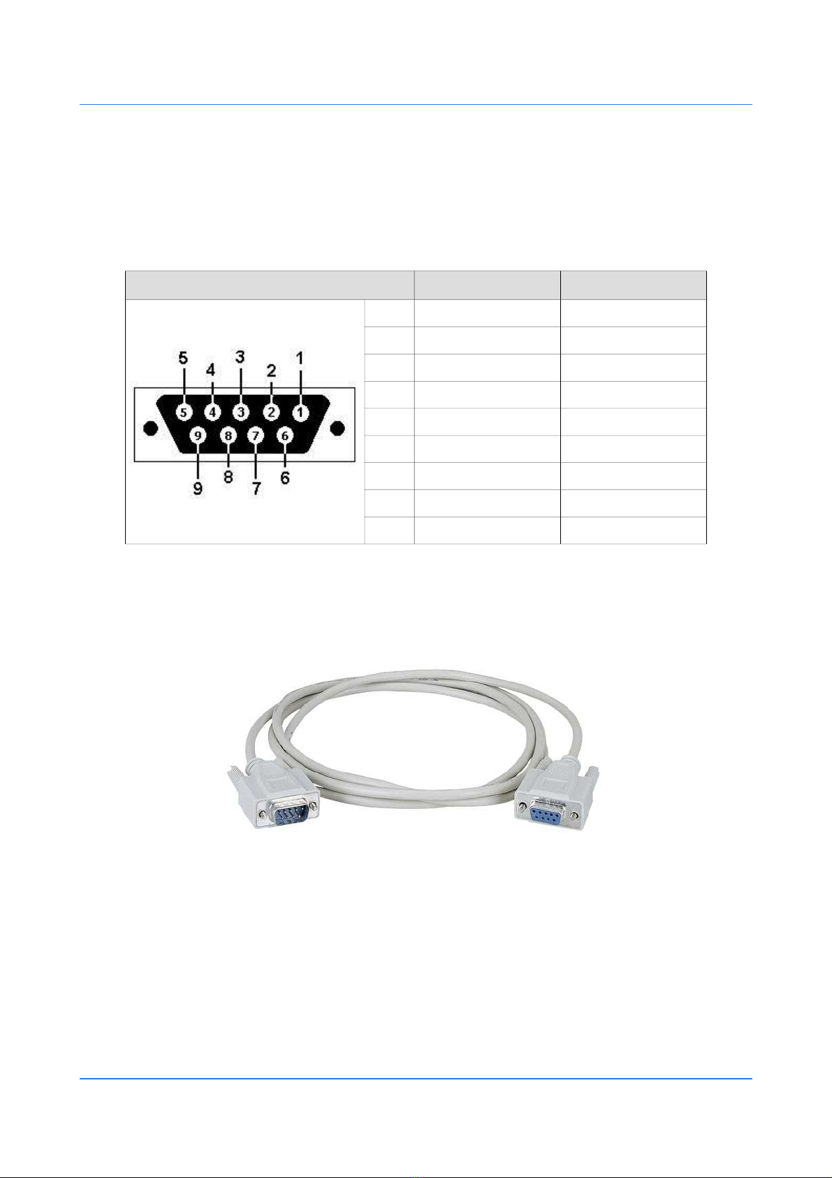
3.4 RS232 serial interface
RS-232 communication with user device or PC can be established via standard DB9 female
connector. GT340 acts li e standard DCE device.
Auto baud rate detection is set by default, format is 8N1, with enabled hardware flow control.
RS232 pinout Signal Type
1 DCD RS-232 Output
2 RxD RS-232 Output
3 TxD RS-232 Input
4 DTR RS-232 Input
5 GND Signal Ground
6 DSR RS-232 Output
7 RTS RS-232 Input
8 CTS RS-232 Output
RI RS-232 Output
Serial RS232 cable with DB9 male and DB9 female connectors is obtained separately. For
ordering details see chapter 2.2 Accessories.
w
w
w
.
d
e
c
o
d
e
.
r
s
1
1
/
2
6
Fig. 7: Serial cable

User's Manual GSM Terminal GT340 Device Description
3.5 Power supply
GSM Terminal GT340 must be powered with DC power supply in range from 8V to 30V. Follow
polarity designation on the rear panel of the device. Device has overvoltage protection (TVS
diode) and it is protected against reverse polarity (serial diode).
One can choose optional AC/DC adapter for wall mounting, or industrial grade power supply
for 35mm DIN rail mounting. For ordering details see chapter 2.2 Accessories.
The power supply of the device can be controlled using the DTR pin on the RS232 port. On the
rear panel of the device, it is necessary to remove two torx screws using the T8 screwdriver.
Remove the bac panel and carefully remove the PCB out of the case.
The jumper PWR_EN (close to the RS232 connector) defines how the power is turned on:
- in place – power is always ON
- removed – the power is turned ON by the DTR signal on the RS232 port
Choose how to turn on the power, return the PCB to the case, and mount the rear panel.
3.6 DIN rail mounting holder
DIN rail mounting holder can be mounted on the device and secured by two screws M3x5
(included with holder). For ordering details see chapter 2.2 Accessories.
w
w
w
.
d
e
c
o
d
e
.
r
s
1
2
/
2
6
Fig. 9: Power suppl 24V 15W,
35mm DIN rail mount, 17.5x90x58.4mm
Fig. 8: AC/DC adapter 12V 12W,
wall mount, 25x75x40mm
Fig. 10: 35mm DIN rail mounting holder
User's Manual GSM Terminal GT340 Operation description
4 Operation description
4.1 Basic operation
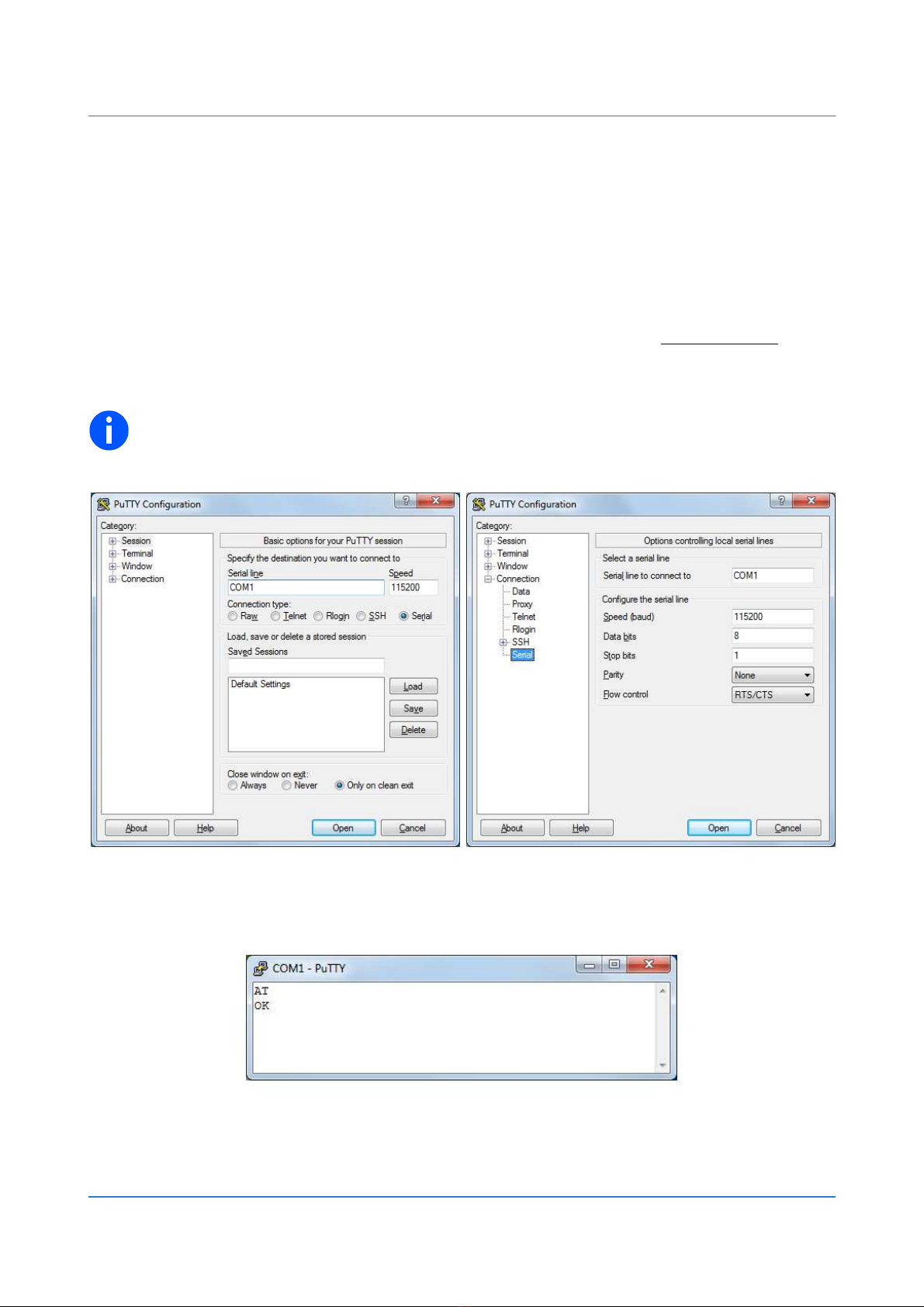
4.1.1 Terminal program
For communication and setting up the GT340, one can use terminal program such as “PuTTY”.
It is an open source software and can be downloaded, free of charge, at www.putty.org.
Choose the correct COM port and serial port parameters (e.g. 115200bps, 8bits, no parity bit,
1 stop bit, RTS/CTS hardware flow control).
NOTE: Auto baud rate detection is set by default. Issuing “ AT↲ ” command sets the
device to chosen baudrate.
w
w
w
.
d
e
c
o
d
e
.
r
s
1
3
/
2
6
Fig. 12: Issuing AT command
Fig. 11: PuTTY terminal program
User's Manual GSM Terminal GT340 Operation description
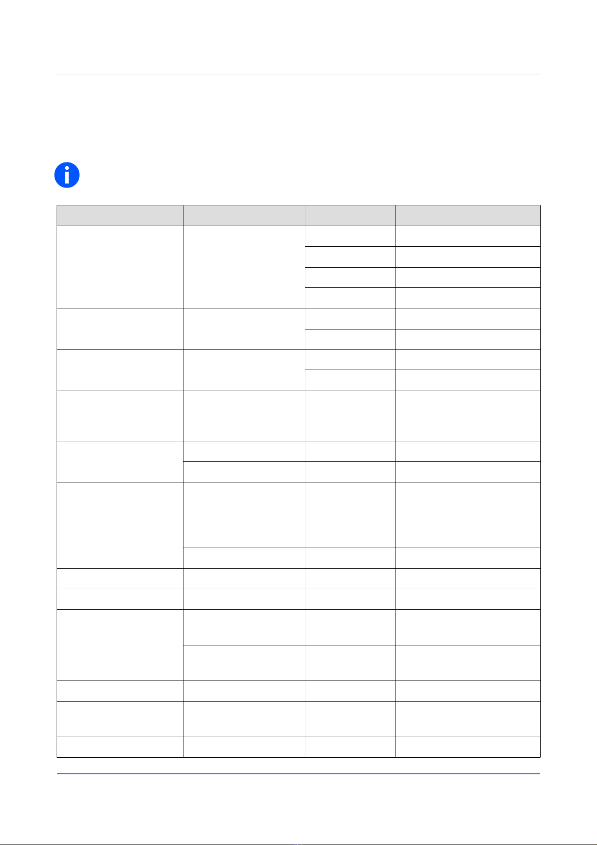
4.1.2 AT command guide
Following are examples of some AT commands. Please refer to the “u-blox AT Commands
Manual” for a full description.
NOTE: Issue “ AT+CMEE=1↲ ” to have extended error code (+CME ERROR), and
“ AT+CMGF=1↲ ” for text mode as preferred message format.
Description AT commands Response Comments
Networ
registration
chec ing
AT+CREG?
+CREG: 0,0 Not registered
+CREG: 0,1 Registered, home networ
+CREG: 0,2 Searching operator
+CREG: 0,5 Registered, roaming
Chec if PIN is required AT+CPIN? +CPIN: READY PIN not required
+CPIN: SIM PIN PIN is required
Enter PIN code AT+CPIN=1234 OK PIN code accepted
CME ERROR: 16 Incorrect PIN code
Receiving signal
strength AT+CSQ +CSQ: 21,99
The first parameter has to
be at least 10 for normal
communication
Receiving an
incoming call
RING Incoming call
ATA OK Answer the call
Ma e a call,
or ma e an
emergency call
ATD1234567;
ATD112; OK
Communication
established
Note: use “ ; ” at the end
for voice call
NO CARRIER Communication loss
Hang up call ATH OK Call ended
List all SMS messages AT+CMGL=”ALL” +CMGL: ... Lists all SMS messages
Send SMS message
AT+CMGS=”1234567”
↲>Initiate sending message,
wait for “ > ”
this is the text
CTRL+Z
+CMGS: 1
OK
Enter the text and issue
“ CTRL+Z “ to send
Set GSM LED AT+UGPIOC=16,2 OK Set LED OK
Save parameters in
non volatile memory AT&W OK The configuration settings
are stored
Safe power down AT+CPWROFF OK GSM module OFF
w
w
w
.
d
e
c
o
d
e
.
r
s
1
4
/
2
6
User's Manual GSM Terminal GT340 Operation description
4.1.3 Factory settings
In the following table are some of the factory settings for GT340 Terminal. Please refer to the
“u-blox AT Commands Manual” for a full description.
AT command Factory
settings Description
AT+IPR 0 Auto baud rate detection
AT+IFC 2,2 RTS/CTS hardware flow control
AT+ICF 0,0 Auto detect format, odd parity
ATE 1 Echo ON
AT&C 1 DCD ON if the Carrier is detected, OFF otherwise
AT&D 1 DTR ON-OFF transition – DCE enters command state
ATQ 0 DCE transmits result codes
ATV 1 DCE transmits verbose response text
AT&S 1 DSR ON in data mode, OFF in command mode
ATS0 0 Automatic answer disabled
AT+CLIP 0 Calling line identification presentation disabled
AT+CSCS “IRA” International Reference Alphabet (ITU-T T.50)
AT+CMGF 0 Preferred message format – PDU mode
AT+CSMP 17,167,0,0 Text mode parameters
AT+CNMI 1,0 New message indication procedure
AT+UGPIOC 16,2 Networ status indication mapped to LED GSM
w
w
w
.
d
e
c
o
d
e
.
r
s
1
5
/
2
6
User's Manual GSM Terminal GT340 Operation description
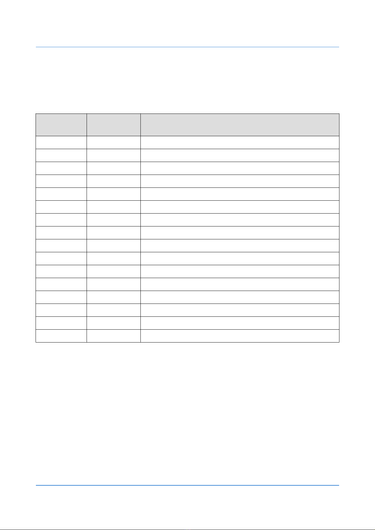
4.2 Dial-up connection
This chapter explains how to install modem driver and create dial-up connection for data
transmission via GSM/GPRS service.
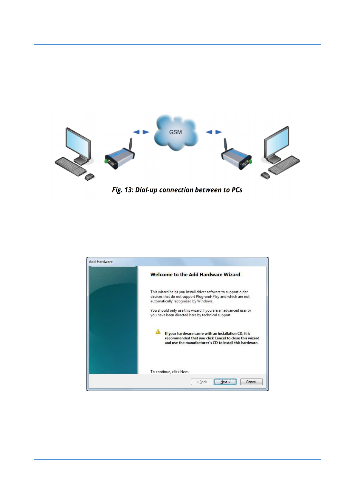
4.2.1 Modem driver Installation
Install the modem driver using the Control Panel -> Add New Hardware Wizard (Windows XP), or
typing hdwwiz in the Start Menu -> Search programs and files (Windows 7):
Clic Next.
w
w
w
.
d
e
c
o
d
e
.
r
s
1
6
/
2
6
Fig. 14: Add Hardware

User's Manual GSM Terminal GT340 Operation description
In the next window mar nstall the hardware that manually select from a list (Advanced):
Clic Next.
In the next window choose Modems:
Clic Next.
w
w
w
.
d
e
c
o
d
e
.
r
s
1
7
/
2
6
Fig. 15: Install the hardware
Fig. 16: Choose Modems

User's Manual GSM Terminal GT340 Operation description
Mar field Don't detect my modem; will select it from list. Clic Next.
In the next window choose Standard 9600 bps Modem:
Clic Next.
w
w
w
.
d
e
c
o
d
e
.
r
s
1
8
/
2
6
Fig. 17: Choose from a list
Fig. 18: Choose Standard 9600 bps Modem
User's Manual GSM Terminal GT340 Operation description
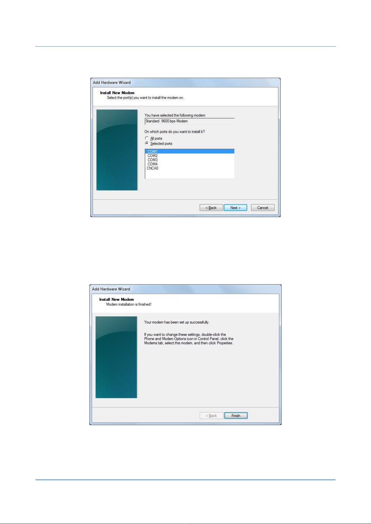
Choose serial port to which modem is connected:
Clic Next.
Wait for installation of modem driver to be finished.
Clic Finish.
w
w
w
.
d
e
c
o
d
e
.
r
s
1
9
/
2
6
Fig. 19: Choose serial port
Fig. 20: Finished modem install
User's Manual GSM Terminal GT340 Operation description
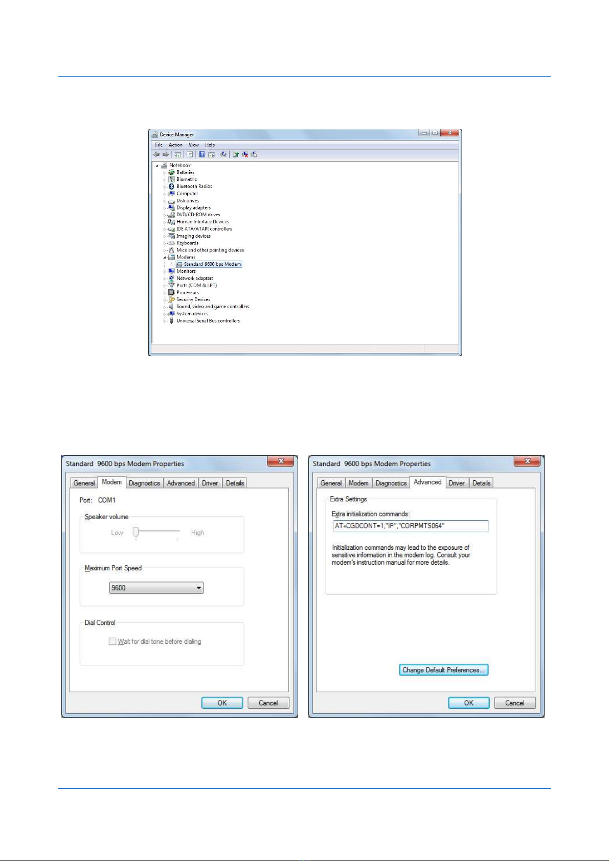
Open Device Manager and expand Modems group:
Right clic on Standard 9600 bps Modem and choose Properties. In field Extra initialization
commands enter APN name.
For example, for MTS provider, enter command AT+CGDCONT=1,"IP","CORPMTS064".
w
w
w
.
d
e
c
o
d
e
.
r
s
2
0
/
2
6
Fig. 21: Device Manager
Fig. 22: Modem Properties
Table of contents


