deconta green dec G 50 User manual
Operating instructions (original)
green dec
G 50, G 100, G 200, G 300, G 400, G 500
G 50
G 100
G 200
G 300
G 400
G 500
deconta GmbH
Im Geer 20
46419 Isselburg
Language: EN
Version: 4
Issue Date:
24.07.2023

Table of contents
Negative pressure unit green dec G 50, G 100, G 200, G 300, G 400, G 500 2 from 83
Original operating instructions Version 4
1Product and manufacturer..............................................................................................6
1.1 Product...................................................................................................................6
1.2 Manufacturer..........................................................................................................6
1.3 Change index.........................................................................................................6
2About these operating instructions................................................................................7
2.1 Purpose..................................................................................................................7
2.2 Availability..............................................................................................................7
2.3 Warnings................................................................................................................8
2.3.1 Warning words and warning colours.........................................................8
2.3.2 Structure...................................................................................................8
2.4 Symbols.................................................................................................................9
2.4.1 Warning sign.............................................................................................9
2.4.2 Instruction sign .........................................................................................9
3Description of the machine...........................................................................................10
3.1 General description..............................................................................................10
3.2 Scope of delivery..................................................................................................10
3.3 Return delivery after termination of a lease ..........................................................10
3.4 Operating modes..................................................................................................11
3.4.1 Available operating modes......................................................................11
3.5 Interfaces.............................................................................................................11
3.6 Type plate ............................................................................................................12
3.6.1 Content...................................................................................................12
3.6.2 Version...................................................................................................12
3.6.3 Position...................................................................................................12
3.7 Accessories..........................................................................................................12
3.7.1 Negative pressure unit green dec G 50...................................................12
3.7.2 Negative pressure unit green dec G 100.................................................14
3.7.3 Negative pressure unit green dec G 200.................................................15
3.7.4 Negative pressure unit green dec G 300.................................................16
3.7.5 Negative pressure unit green dec G 400 and G 500...............................18
4Technical data................................................................................................................19
4.1 Dimensions ..........................................................................................................19
4.2 Weights................................................................................................................19
4.3 Performance data.................................................................................................19
4.3.1 Negative pressure unit green dec G 50...................................................19
4.3.2 Negative pressure unit green dec G 100.................................................20
4.3.3 Negative pressure unit green dec G 200.................................................20
4.3.4 Negative pressure unit green dec G 300.................................................21
4.3.5 Negative pressure unit green dec G 400.................................................22
4.3.6 Negative pressure unit green dec G 500.................................................23
4.4 Performance data special versions.......................................................................24
4.4.1 Negative pressure unit green dec G 50...................................................24
4.4.2 Negative pressure unit green dec G 100.................................................24

Table of contents
Negative pressure unit green dec G 50, G 100, G 200, G 300, G 400, G 500 3 from 83
Original operating instructions Version 4
4.4.3 Negative pressure unit green dec G 200.................................................24
4.4.4 Negative pressure unit green dec G 300.................................................25
4.4.5 Negative pressure unit green dec G 400.................................................25
4.4.6 Negative pressure unit green dec G 500.................................................25
4.5 Environmental conditions .....................................................................................25
4.6 Noise emission.....................................................................................................26
4.7 Filter description / classification............................................................................27
5Security..........................................................................................................................29
5.1 Intended use ........................................................................................................29
5.2 Misapplication ......................................................................................................30
5.3 Tasks and qualifications of the staff......................................................................31
5.4 Notes on occupational health and safety..............................................................32
6Transport........................................................................................................................33
6.1 Loss of warranty claims........................................................................................33
6.2 Off-site transport...................................................................................................33
6.2.1 Transport space......................................................................................33
6.2.2 Legislation ..............................................................................................33
6.2.3 Qualification of the staff ..........................................................................33
6.2.4 Warning of residual risks.........................................................................33
6.2.5 Means of transportation..........................................................................34
6.3 Internal transport..................................................................................................34
6.3.1 Transport space......................................................................................34
6.3.2 Legislation ..............................................................................................34
6.3.3 Warning of residual risks.........................................................................34
6.3.4 Means of transportation..........................................................................34
7Assembly........................................................................................................................35
8Operation........................................................................................................................36
8.1 Qualification of the staff........................................................................................36
8.2 Warning of residual risks......................................................................................36
8.3 Personal protective equipment required...............................................................36
8.4 Number of persons...............................................................................................36
8.5 Tools needed .......................................................................................................36
8.6 Required equipment.............................................................................................36
8.7 Negative pressure unit with control SE.................................................................37
8.7.1 Room negative pressure maintenance....................................................37
8.8 Negative pressure units with SRE connect control ...............................................38
8.8.1 Create user account ...............................................................................39
8.8.2 Add the machine to the user account......................................................40
8.8.3 Preparation.............................................................................................43
8.8.4 Manual operation....................................................................................43
8.8.5 Automatic operation................................................................................44
8.8.6 Day / Night Settings (Day / Night)...........................................................45
8.8.7 Standby mode ........................................................................................45

Table of contents
Negative pressure unit green dec G 50, G 100, G 200, G 300, G 400, G 500 4 from 83
Original operating instructions Version 4
8.8.8 Consumption ..........................................................................................46
8.8.9 Dust Sensor............................................................................................46
8.8.10 Service ...................................................................................................47
8.8.11 Device information..................................................................................49
8.8.12 Alarms....................................................................................................50
8.8.13 Switch off the unit ...................................................................................52
9Maintenance...................................................................................................................53
9.1 Loss of warranty claims........................................................................................53
9.2 Maintenance.........................................................................................................53
9.3 Warning of residual risks......................................................................................53
9.3.1 Personal protective equipment required..................................................54
9.4 Filter change information......................................................................................54
9.4.1 Control SE..............................................................................................54
9.4.2 Control SRE connect..............................................................................55
9.5 Filter change ........................................................................................................55
9.5.1 Procedure using the G 300 as an example.............................................56
9.6 Troubleshooting and fault clearance.....................................................................59
9.6.1 Possible malfunctions and tips for rectifying malfunctions.......................59
10 Spare parts.....................................................................................................................60
10.1 Negative pressure unit green dec G 50................................................................60
10.2 Negative pressure unit green dec G 100..............................................................61
10.3 Negative pressure unit green dec G 200..............................................................62
10.4 Negative pressure unit green dec G 300..............................................................63
10.5 Negative pressure unit green dec G 400..............................................................64
10.6 Negative pressure unit green dec G 500..............................................................65
11 Circuit diagrams ............................................................................................................66
11.1 Negative pressure unit green dec G 50 SE, 110 volt version................................66
11.2 Negative pressure unit green dec G 50 SE, 230 volt version................................67
11.3 Negative pressure unit green dec G 100 SE, 110 volt version..............................68
11.4 Negative pressure unit green dec G 100 SE, 230 volt version..............................69
11.5 Negative pressure unit green dec G 100 SRE connect, 230 volt version..............70
11.6 Negative pressure unit green dec G 200 SE, 110 volt version..............................71
11.7 Negative pressure unit green dec G 200 SE, 230 volt version..............................72
11.8 Negative pressure unit green dec G 200 SRE connect, 230 volt version..............73
11.9 Negative pressure unit green dec G 300 SE, 110 volt version..............................74
11.10 Negative pressure unit green dec G 300 SE, 230 volt version..............................75
11.11 Negative pressure unit green dec G 300 SRE connect, 230 volt version..............76
11.12 Negative pressure unit green dec G 400 SE, 230 volt version..............................77
11.13 Negative pressure unit green dec G 400 SRE connect, 230 volt version..............78
11.14 Negative pressure unit green dec G 500 SE, 230 volt version..............................79
11.15 Negative pressure unit green dec G 500 SRE connect, 230 volt version..............80
12 Storage...........................................................................................................................81
12.1 Environmental conditions .....................................................................................81

Table of contents
Negative pressure unit green dec G 50, G 100, G 200, G 300, G 400, G 500 5 from 83
Original operating instructions Version 4
12.2 Requirements.......................................................................................................81
13 Disposal .........................................................................................................................82
13.1 Qualification of the staff........................................................................................82
13.2 Legislation............................................................................................................82
13.3 Waste...................................................................................................................82
14 EC Declaration of Conformity.......................................................................................83
Product and manufacturer
Negative pressure unit green dec G 50, G 100, G 200, G 300, G 400, G 500 6 from 83
Original operating instructions Version 4
1 Product and manufacturer
1.1 Product
This operating manual describes the following product:
Negative pressure unit green dec.
Types: G 50, G 100, G 200, G 300, G 400, G 500
1.2 Manufacturer
Name and address
deconta GmbH
Im Geer 20
46419 Isselburg
Phone
02874/9156-0
Fax
02874/9156-11
E-mail
Internet
www.deconta.com
1.3 Change index
Date
Version
Change
Responsible
07.03.2023
4
complete revision
Thomas Boland
About these operating instructions
Negative pressure unit green dec G 50, G 100, G 200, G 300, G 400, G 500 7 from 83
Original operating instructions Version 4
2 About these operating instructions
For proper and safe use of the machine, follow the descriptions and recommended actions
in these operating instructions.
Keep this manual for future reference until the machine has been disposed of.
2.1 Purpose
These operating instructions contain information on the safe, trouble-free and economical
use of the machine.
This information is intended for persons who perform tasks with or in connection with the
machine.
The following table gives an overview of persons and tasks.
Person
Task
Operator
<< Machine-specific >>
Occupational safety specialist
•Carry out a risk assessment
•Create operating instructions
•Instruct people
Maintenance staff
Maintenance of the mechanics
Electrician (EFK)
Installation and maintenance of electrical
equipment
Freight forwarder
Off-site transport of the machine
Conveyor
Internal transport of the machine
Disposer
Dispose of the machine in a legally
compliant, proper and professional
manner.
2.2 Availability
The operator shall make these operating instructions or extracts thereof available to
persons who perform tasks with or in connection with the machine.
The operator keeps these operating instructions or extracts thereof within easy reach in the
immediate vicinity of the machine.
When handing over the machine to another person, the operator passes these operating
instructions on to that person.
About these operating instructions
Negative pressure unit green dec G 50, G 100, G 200, G 300, G 400, G 500 8 from 83
Original operating instructions Version 4
2.3 Warnings
These operating instructions contain warnings of residual dangers.
The classification of the warnings is based on the severity of the damage that can occur if
the warnings are disregarded and recommended actions are not followed.
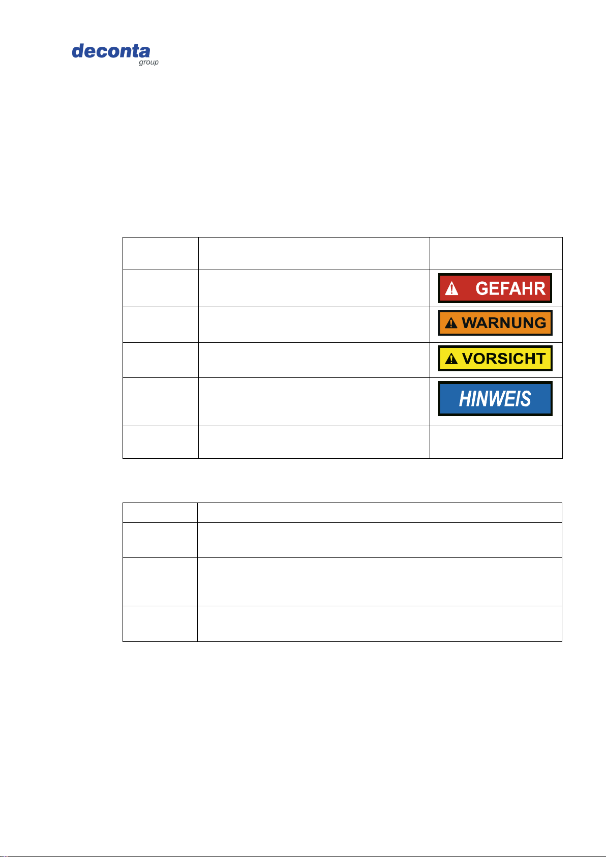
2.3.1 Warning words and warning colours
Warnings are introduced with one of the following warning words and marked with a
corresponding warning colour.
Warning
word
Meaning
Warning colour
DANGER
Consequence for non-compliance:
Death or most serious injuries.
WARNING
Consequence for non-compliance:
Death or most severe injuries possible.
CAUTION
Consequence for non-compliance:
Severe or minor injuries possible.
NOTE
Consequence for non-compliance:
Property damage or environmental
damage possible.
SAFE
ACTIVITY
Implement the following action guide.
-
2.3.2 Structure
Warnings are structured according to the SAFE method:
S
Warning word (DANGER; WARNING, CAUTION or NOTE)
A
Nature and source of the hazard
Description of the hazard and the cause of the hazard
F
Follow
Description of the possible consequences for humans, animals and
the environment that may occur as a result of the hazard.
E
Escape
Recommendations for action on how to avoid hazards
About these operating instructions
Negative pressure unit green dec G 50, G 100, G 200, G 300, G 400, G 500 9 from 83
Original operating instructions Version 4
2.4 Symbols
The following symbols are used in these operating instructions.
2.4.1 Warning sign
The warning sign is a safety sign that warns of a risk or danger.
The following table gives an overview of warning signs used and their meaning.
Symbol
Meaning
Symbol
Meaning
Warning of electrical
voltage
General warning sign
2.4.2 Instruction sign
The instruction sign is a safety sign that prescribes a certain behaviour.
The following table gives an overview of the instruction signs used and their meaning.
Symbol
Meaning
Symbol
Meaning
Use hearing protection
Use protective clothing
Wear safety shoes

Description of the machine
Negative pressure unit green dec G 50, G 100, G 200, G 300, G 400, G 500 10 from 83
Original operating instructions Version 4
3 Description of the machine
This section contains information for understanding the machine.
3.1 General description
General description of the product
The machine (the negative pressure unit) was designed and built by the company deconta
GmbH, Im Geer 20, 46419 Isselburg.
Negative pressure unit for filtering asbestos-contaminated room air via a 3-stage filter unit
(G 50 only 2-stage). The built-in HEPA filter meets the requirements of EN 1822 class H 13
or H 14.
Procedure for carrying out the risk assessment for machinery
•Language of the risk assessment: German
•Risk assessment: EN ISO 12100 Safety of machinery - General principles for design - Risk
assessment and risk reduction, three-step iterative process for risk reduction in conjunction with
Machinery Directive 2006/42/EC, Annex I, first general principle.
•Risk assessment: DIN ISO/TR 14121-2 Safety of machinery - Risk assessment - Part 2: Practical
guide and examples of procedures, 6.3 Risk graph; Determination of the required performance
level (PLr): EN ISO 13849-1 Safety of machinery - Safety-related parts of control systems - Part
1: General principles for design; Determination of SIL (Safety Integrity Level): EN 62061 Safety
of machinery - Functional safety of safety-related electrical, electronic and programmable
electronic control systems.
3.2 Scope of delivery
The delivery scope of the machine includes the following items:
•Negative pressure unit green dec
•These operating instructions
•Transport cover
•Sealing plug
3.3 Return delivery after termination of a lease
For the protection of our customers and in terms of dangerous goods transport regulations,
we must insist on the following return delivery conditions:
▪As listed above
▪Thoroughly cleaned (ready for use)
▪Free from any adhesive residues
▪Without residual fibre encapsulation
▪Without filter
▪Without damage

Description of the machine
Negative pressure unit green dec G 50, G 100, G 200, G 300, G 400, G 500 11 from 83
Original operating instructions Version 4
3.4 Operating modes
3.4.1 Available operating modes
Type of use
The machine is intended exclusively for use in the following types of use.
Use for other types of use is not in accordance with the intended use.
User groups
▪Commercial users
User environment
▪outdoors
▪on roofed areas
▪in rooms closed on all sides
Operating modes
Operating modes for use:
▪Automatic mode (SRE connect version only)
▪Manual operation
3.5 Interfaces
This section contains information about interfaces.
The following interfaces are available on the machine:
▪Human product: Control panel, touch screen
▪Product power supply: Electrical power supply 110 V / 230 V / 400 V
▪Product waste: Connection spigot for clean air
▪Product material feed: Connecting piece for contaminated air
▪Product building: feet or castor wheels
Description of the machine
Negative pressure unit green dec G 50, G 100, G 200, G 300, G 400, G 500 12 from 83
Original operating instructions Version 4
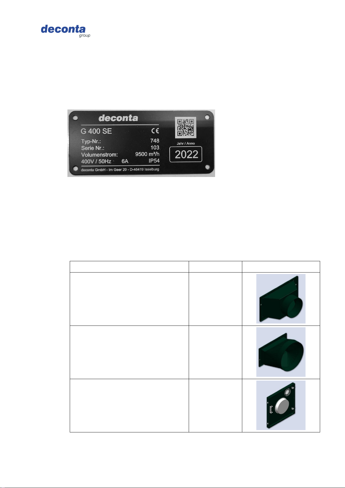
3.6 Type plate
The type plate contains information for identifying the machine.
3.6.1 Content
The following illustration shows an example type plate.
3.6.2 Version
Aluminium plate, riveted
3.6.3 Position
Near the control panel on the outlet side.
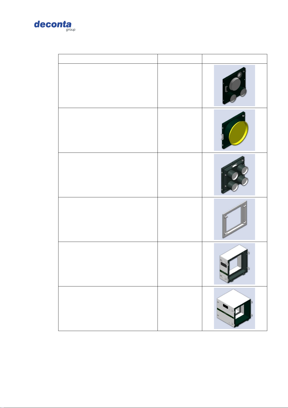
3.7 Accessories
The following accessories are optionally available for the machine:
3.7.1 Negative pressure unit green dec G 50
Designation
Item no.
Illustration
Air outlet flange NW 150
BO13928
Air outlet flange NW 300
BO13931
Inlet flange NW 150
BO13949
Description of the machine
Negative pressure unit green dec G 50, G 100, G 200, G 300, G 400, G 500 13 from 83
Original operating instructions Version 4
Designation
Item no.
Illustration
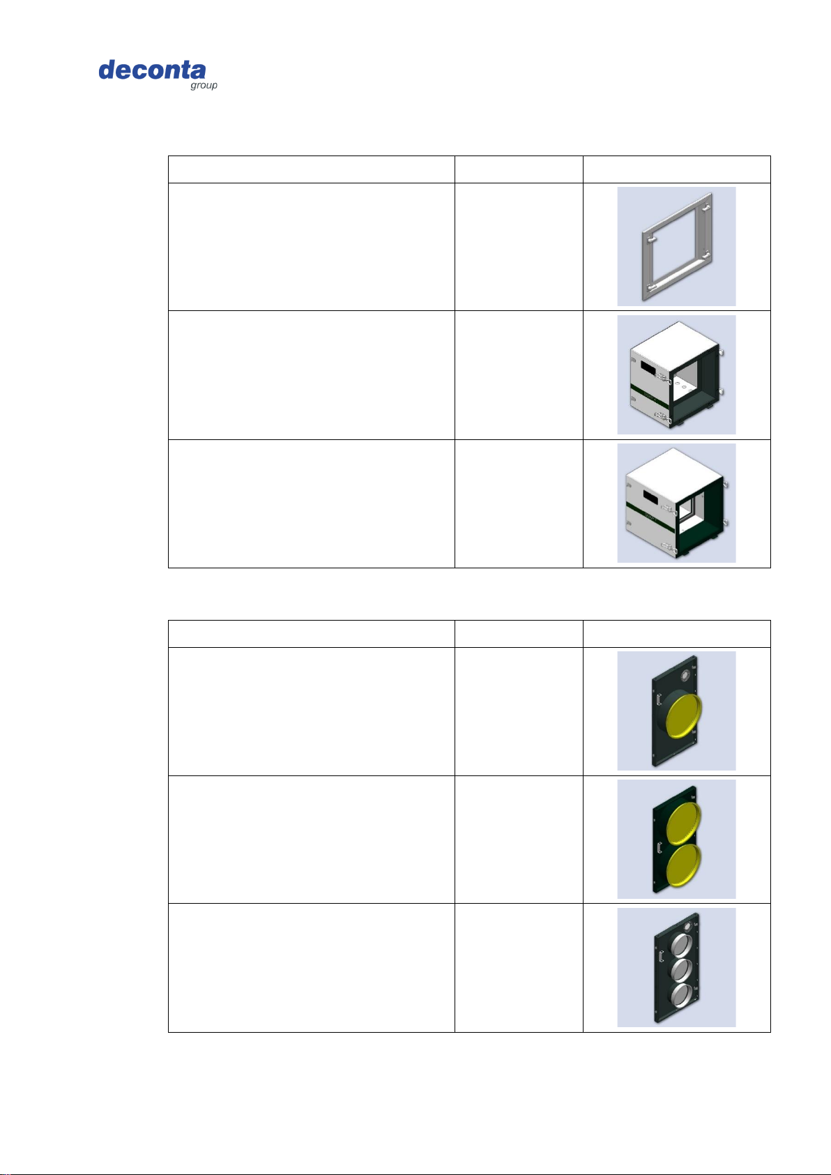
Inlet flange 1x NW 150 and
2x NW 100
BO20998
Inlet flange NW 300
BO15422
Adapter 4-fold, 4 x NW 100,
Individually adjustable
BO14211
Adhesive frame
BO23144
SNAP A double filtration
687
SNAP T pocket filter
682
Description of the machine
Negative pressure unit green dec G 50, G 100, G 200, G 300, G 400, G 500 14 from 83
Original operating instructions Version 4
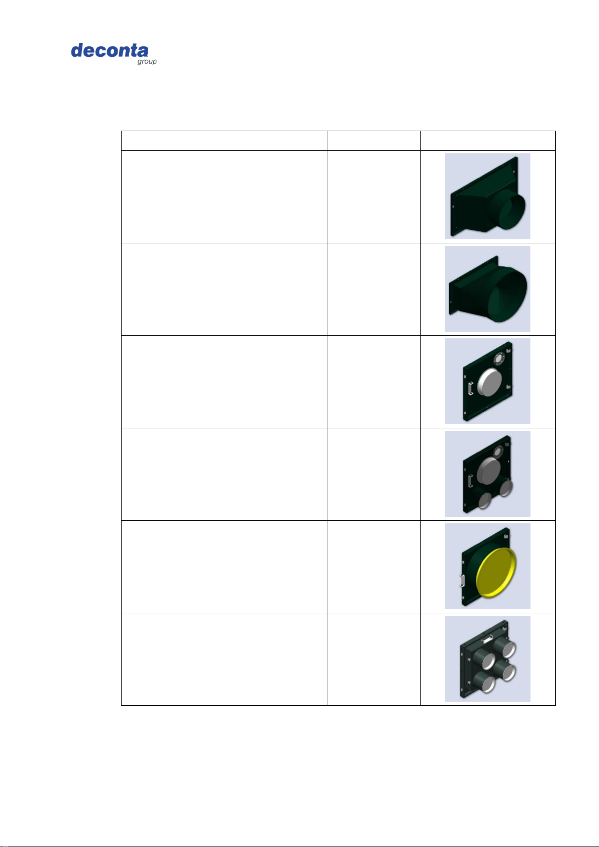
3.7.2 Negative pressure unit green dec G 100
Designation
Item no.
Figure
Air outlet flange NW 150
BO13928
Air outlet flange NW 300
BO13931
Inlet flange NW 150
BO13949
Inlet flange 1x NW 150 and
2x NW 100
BO20998
Inlet flange NW 300
BO15422
Adapter 4-fold, 4 x NW 100,
Individually adjustable
BO14211
Description of the machine
Negative pressure unit green dec G 50, G 100, G 200, G 300, G 400, G 500 15 from 83
Original operating instructions Version 4
Designation
Item no.
Figure
Adhesive frame
BO23144
SNAP A double filtration
681
SNAP T pocket filter
682
3.7.3 Negative pressure unit green dec G 200
Designation
Item no.
Figure
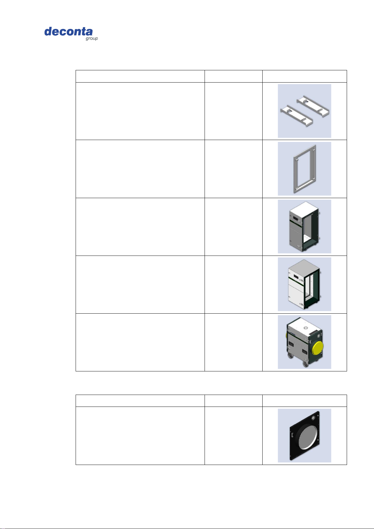
Inlet flange NW 300
BO14010
Inlet flange 2 x NW 300
BO19660
Inlet flange 3 x NW 150
BO16629
Description of the machine
Negative pressure unit green dec G 50, G 100, G 200, G 300, G 400, G 500 16 from 83
Original operating instructions Version 4
Designation
Item no.
Figure
Stacking device set
BO14701
Adhesive frame
BO23141
SNAP A double filtration
685
SNAP T pocket filter
686
Filter unit FG 200 SNAP
765
3.7.4 Negative pressure unit green dec G 300
Designation
Item no.
Figure
Inlet flange NW 450
BO14695
Description of the machine
Negative pressure unit green dec G 50, G 100, G 200, G 300, G 400, G 500 17 from 83
Original operating instructions Version 4
Designation
Item no.
Figure
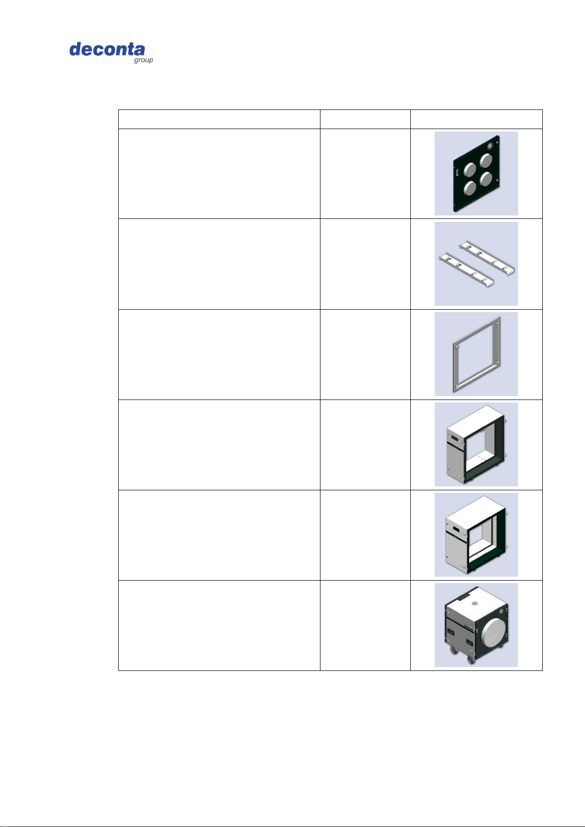
Inlet flange 4x NW 150
BO22214
Stacking device set
BO14702
Adhesive frame
BO23138
SNAP A double filtration
669
SNAP T pocket filter
684
Filter unit FG 300 SNAP
697
Description of the machine
Negative pressure unit green dec G 50, G 100, G 200, G 300, G 400, G 500 18 from 83
Original operating instructions Version 4
3.7.5 Negative pressure unit green dec G 400 and G 500
Designation
Item no.
Figure
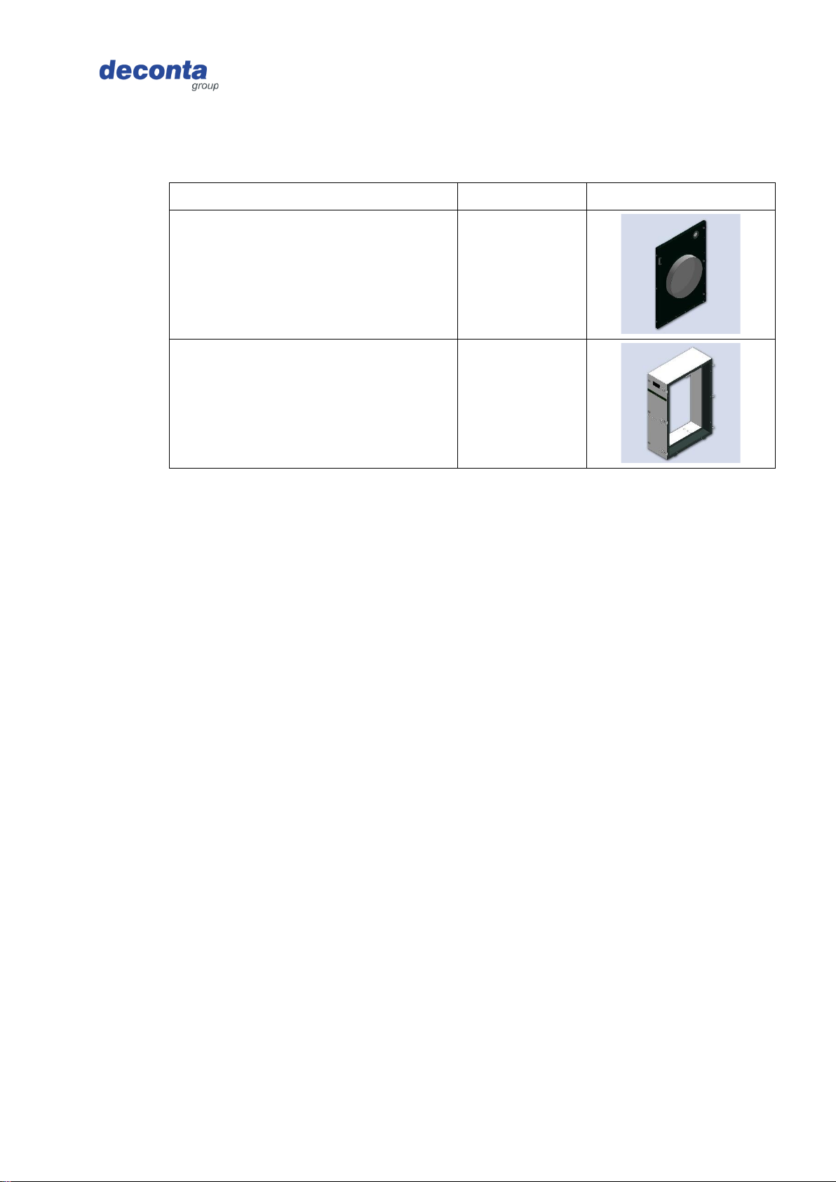
Inlet flange NW 450
BO20486
SNAP A double filtration
806
Technical data
Negative pressure unit green dec G 50, G 100, G 200, G 300, G 400, G 500 19 from 83
Original operating instructions Version 4
4 Technical data
4.1 Dimensions
Length x width x height (mm)
G 50
525 x 390 x 390
G 100
770 x 410 x 410
G 200
970 x 410 x 840
G 300
1150 x 720 x 840
G 400
1200 x 720 x 1150
G 500
Fan unit1180 x 785 x 955
Filter unit715 x 720 x 1150
4.2 Weights
Weight incl. filter (kg)
G 50
18,8
G 100
27,5
G 200
55,0
G 300
79,0
G 400
105,0
G 500
Fan unit110 .0
Filter unit63 .0
4.3 Performance data
All data on air performance and volumetric flows taking into account a measurement
tolerance of ±15% referred to the measuring range end value, determined in a multi-point
measurement procedure with a calibrated impeller anemometer.
4.3.1 Negative pressure unit green dec G 50
110 V
230 V
Air output free-blowing max.
1500 m³/h
1500 m³/h
Air performance with deconta H13 or H14
filter, max.
1100 m³/h
1100 m³/h
Air performance with deconta H13 or H14
filter, prefilter, max.
1000 m³/h
1000 m³/h
Power connection
100 - 120 V
230 V
Power consumption
3 A
1,2 A
Engine power
0.17 kW
0.17 kW
Technical data
Negative pressure unit green dec G 50, G 100, G 200, G 300, G 400, G 500 20 from 83
Original operating instructions Version 4
110 V
230 V
Power cable type
H07RN-F 3G1.5
Protection class
I
Protection class
IP 54
Filter system
2-stage
Pre-filter
EU 4
HEPA filter
according to EN 1822 class H13 or H14
4.3.2 Negative pressure unit green dec G 100
110 V
230 V
Air output free-blowing max.
2000 m³/h
2300 m³/h
Air performance with deconta H13 or H14
filter, max.
1500 m³/h
1800 m³/h
Air performance with deconta H13 or H14
filter, pre- and intermediate filter, max.
1350 m³/h
1650 m³/h
Power connection
100 - 120 V
230 V
Power consumption
4 A
2,5 A
Engine power
0.345 kW
0.5 kW
Power cable type
H07RN-F 3G1.5
Protection class
I
Protection class
IP 54
Filter system
3-stage
Pre-filter
EU 3
Intermediate filter
EU 4
HEPA filter
according to EN 1822 class H13 or H14
4.3.3 Negative pressure unit green dec G 200
110 V
230 V
Air output free-blowing max.
4000 m³/h
4500 m³/h
Air performance with deconta H13 or H14
filter, max.
3050 m³/h
3400 m³/h
Air performance with deconta H13 or H14
filter, pre- and intermediate filter, max.
2500 m³/h
3000 m³/h
Power connection
100 - 120 V
230 V
Power consumption
7 A
4 A
Engine power
2x 0.345 kW
0.75 kW
Other manuals for green dec G 50
1
This manual suits for next models
5
Table of contents
Other deconta Vacuum Cleaner manuals


