deconta ME 12 User guide
Original instruction manual
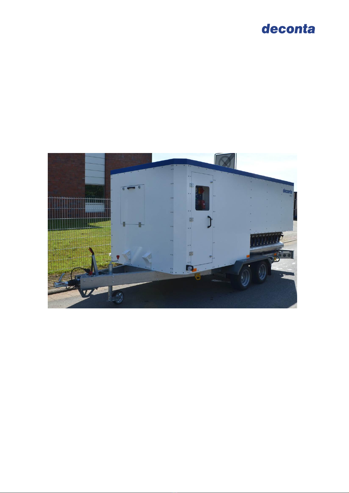
Mobile Deduster
ME 12
Manufacturer: deconta GmbH
Im Geer 20, 46419 Isselburg
Description / Type-No.: Mobile Deduster ME 12 Type 94, 565
Serial-No.: .................

Instruction manual
Mobile Deduster ME 12
Version 1 Seite 2
Table of contents
1.Basic safety advice............................................................................................................3
1.1.Intended use....................................................................................................................................4
1.2.Dangers...........................................................................................................................................4
2.Transport and storage.......................................................................................................5
2.1.Delivery / Transport .........................................................................................................................5
2.1.1.Coupling to towing vehicle.......................................................................................................5
2.1.2.Uncoupling...............................................................................................................................6
2.2.Storage ............................................................................................................................................6
3.Volume of delivery .............................................................................................................6
4.Technical data....................................................................................................................7
4.1.Connections, dimensions and weights............................................................................................7
4.2.Performance data............................................................................................................................7
4.3.Filter data 1. Filter stage (regenerative Filter).................................................................................7
4.4.Filter data 2. Filter stage (HEPA-Filter) ...........................................................................................8
4.5.Requirement for towing vehicle.......................................................................................................8
5.Technical description ........................................................................................................9
5.1.Unit description................................................................................................................................9
5.2.Options.............................................................................................................................................9
5.3.Filter system ....................................................................................................................................9
5.4.Filter cleaning ..................................................................................................................................9
6.Initial operation ................................................................................................................10
6.1.Option automatic control SRE.......................................................................................................11
6.2.Option Dust bunker with filling level control and emptying via suction port ..................................13
7.Maintenance .....................................................................................................................14
7.1.Details on filter change..................................................................................................................14
7.2.Regular maintenance ....................................................................................................................14
8.Possible disturbances and their elimination.................................................................15
9.Declaration of conformity................................................................................................16

Instruction manual
Mobile Deduster ME 12
Version 1 Seite 3
The copyright of this instruction manual remains with deconta. This manual is intended for assembly,
operation and maintenance personnel. It contains instructions and drafts of technical nature which may
neither be distributed nor used in any unauthorised way for competitive purposes or passed on to others.
1.Basic safety advice
The operation of the equipment must only be carried out by trained competent personnel.
The information and instructions contained within this publication are of paramount
importance to the user.
The manual is always to be kept in the immediate proximity, accessible to all personnel.
deconta insists as the equipment user you follow the information and instruction
contained within the handbook and only use it in accordance with the regulations and
never use this Unit in an inappropriate way. In the event of non-observance, deconta
assumes no liability.
To ensure safe operation of the NPU, the following must be strictly observed:
Do not use in potentially explosive atmospheres.
Maintenance work, including removal and replacement of the filters, may only be
carried out by authorized persons wearing suitable protective clothing.
The device must be completely disconnected from the power supply during all
repairs and maintenance work.
The safety and protective systems must be maintained and functioning correctly.
Safety instructions affixed to the unit must be maintained in a legible condition and
must be adhered to.
General, legal and other binding regulations and procedures for accident
prevention and handling of hazardous substances must be observed.
To ensure safety, modifications to the device are not permitted.
To avoid damage, never operate the unit without built-in filters.
ATTENTION!
The Mobile Deduster is not suitable for use in condensing, corrosive, flammable
and explosive atmospheres.
The ambient and medium temperature must not exceed 60 ° C.
We explicitly point out the additional regional and national safety measures and
regulations for the operation of the appliance technology.
The operator must carry out the inspection of the exhaust air at initial acceptance as well
as at a minimum gap of 3 years.
In addition to the instruction manual, general, legal and other binding regulations on
accident prevention and environmental protection must be observed.
Instruction manual
Mobile Deduster ME 12
Version 1 Seite 4
1.1.Intended use
The dust extraction unit is designed for the collection of mineral, metal and other dry fine
and coarse dust in the air.
The unit is not suitable for filtering flammable gases or dusts.
The user must comply with the specified operating parameters of this manual.
The device may only be used according to its intended use. Any further use beyond this
is not intended. The user is liable for any damages or injuries of any kind whatsoever.
1.2.Dangers
DANGER
Electric shock due to faulty mains cable.
Touching a defective mains cable may result in death or serious injury.
Do not damage the mains cable (e.g. by vehicle overrun, tearing, squeezing).
Regularly check the mains cable for damage.
Have defective mains cable replaced before use by the deconta service or a qualified
electrician.
CAUTION
Damage due to unsuitable mains voltage.
The device can be damaged if it is connected to an unsuitable mains voltage.
Check whether the voltage indicated on the rating plate matches the local mains
voltage.
WARNING
Hazardous materials.
The following materials may not be filtered:
hot materials (glowing cigarettes, hot ash etc.)
combustible, explosive, aggressive materials and dusts
WARNING
Contaminated Filter.
Filter changes may only be carried out by authorized persons, wearing suitable
protective clothing.
Disposal of filters according to local legal regulations.

Instruction manual
Mobile Deduster ME 12
Version 1 Seite 5
2.Transport and storage
2.1.Delivery / Transport
For transportation and moving of the Mobile Deduster unit, it is coupled to a towing
vehicle with ball head coupling (requirement see technical data) and pulled to its
destination.
Transport damages are to be documented immediately when handed over. Additionally
take down eventual damages on the freight documents.
2.1.1. Coupling to towing vehicle
Put towing vehicle and Deduster in Position (Move coupling of Deduster over the
trailer ball of towing vehicle)
Pull stabilization handle (Pos.1) upwards
Put opened coupling (Pos.2 coupling handle pulled upwards) by winding down of
support wheel on the trailer ball of the towing vehicle
Release coupling handle handle slides back independently into original position
Use our hand to press down handle locking and securing is done automatically
Press stabilisation handle downwards
Pull up support wheel and lock pointing in driving direction
Fasten breakaway cable to eyelet of trailer coupling (towing vehicle)
Plug in light connector of Deduster into socket of towing vehicle
Check lighting of Deduster
Attention: It is only coupled correctly, if the green edge of the safety indicator
(Pos.3) is visible.
1
2
3

Instruction manual
Mobile Deduster ME 12
Version 1 Seite 6
2.1.2. Uncoupling
Wind down support wheel
Release both breakaway cable and light connector
Pull stabilisation handle (Pos.1) upwards
Pull coupling handle (Pos.2) forcibly upwards
Lift coupling off trailer ball of towing vehicle
Safety instructions:
The trailer coupling may only be operated by one person when opened and closed.
2.2.Storage
To avoid any damages the unit may only be parked in areas inaccessible for
unauthorized persons.
3.Volume of delivery
Regardless if the unit is purchased or rented, unless no other agreements have been
made, the volume of delivery of the Mobile Deduster consists of:
Unit ME 12
Instruction manual
Stoppers
Return delivery after ending of rental period
For the protection of our clients and in accordance with the rules for hazmat transport, we
must insist on the following return delivery conditions:
complete as stated above
thoroughly cleaned (ready-to-operate), with emptied dust bunker
free from any adhesive residue
without fibre binding
without damages

Instruction manual
Mobile Deduster ME 12
Version 1 Seite 7
4.Technical data
4.1.Connections, dimensions and weights
Power connection : 400V 32A 3 N PE
Hose connection : 2 x 300 mm
Length (incl. drawbar) : ca. 5200 mm
Width : ca. 2000 mm
Height : ca. 2010 mm
Weight : ca. 1400 Kg
4.2.Performance data
Exhaust air volume : up to 12000 m³/h
Suction speed : up to 25 m/s
Bunkervolumen : ca. 0,5 m³
Shock valve G1 : 12 pcs
Control : electric 12 channels
Dedusting : continuously
Operating pressure : 4,5bar
4.3.Filter data 1. Filter stage (regenerative Filter)
Filter material :Polyester needle, pleated
Filter area :ca. 100m²
Quantity filters :24 pcs
Filter resistance :4300 Pa
Clean air concentration :< 0,15mg/m³

Instruction manual
Mobile Deduster ME 12
Version 1 Seite 8
4.4.Filter data 2. Filter stage (HEPA-Filter)
Frame Plastic
Filter medium Micro-Glas fibre paper
Casting compound Polyurethane
Sealing Polyurethane
Filter area per filter 48 m²
Filter class H13 pursuant EN 1822
Degree of separation >99,95% leak-tested in MPPS
(Most Penetrated Particle Size)
Temperature / humidity 110°C/100% RF
(relative humidity)
Filter dimensions (in mm): 610 x 910 x 292
Handle protection Expanded metal, double-sided
4.5.Requirement for towing vehicle
Ball head coupling
Permissible drawbar load 75 kg
Ball head 94/20 EG A 50 with min. diameter 49 mm
Control device not rotatable over 25°
technical changes reserved!

Instruction manual
Mobile Deduster ME 12
Version 1 Seite 9
5.Technical description
5.1.Unit description
The dust extraction unit is designed for the collection of mineral, metal and other dry fine
and coarse dust in the air.
mounted on chassis, complete and ready-to-use
quick relocation possible
galvanized tandem chassis with hit brake, TÜV approved
electronic control unit with various special functions
robust construction, designed for continuous operation
recoverable filter system (automatic cleaning during operation)
dust bunker to collect fine and coarse dust
HEPA-Filter stage
high air flow velocity at the inlet side to prevent deposits in the suction line
differential pressure monitoring for filter control
Manual speed control
5.2.Options
Automatic control SRE
Dust bunker with fill level monitoring and emptying via suction connection
5.3.Filter system
The collected fine dust is deposited on the filter surface and forms the “filter cake” (coat).
An automatically working Jet-cleaning system ensures the cleaning of the filters during
operation. The injection nozzles pull air by a suction effect and jet the coat off the filter,
working from inside to the outside. The blown off dust is collected in the dust bunker and
can be removed from there.
5.4.Filter cleaning
The cleaning operates automatically when the compressor and the cleaning are switched
on. The compressor fills the pressure accumulator, which operates the Jet-cleaning
system.
The Deduster is provided with an integrated compressor for short term uses. In
case of long term uses, it is essential to use the external compressed air supply!

Instruction manual
Mobile Deduster ME 12
Version 1 Seite 10
6.Initial operation
The Mobile Deduster ME12 is supplied ex works and is in a ready-to-use state.
In case of visible damages, do not operate the unit. Please contact deconta GmbH
immediately.
Determine the location of the Deduster. Choose it close to the working area to avoid
unnecessary long hoses and loss of power.
Connect suction line of Deduster to working area.
Establish power supply to Deduster (400V 32A 3N PE)
Switch on Main switch, make sure the Lamp „Mains Ok“ lights up
Switch on „Fan“ („Fan active“ lights up) and wait until the motor is running
Switch on „Cleaning“ („Cleaning active“ lights up). When an external Compressor is
connected the lamp “Compressed air external” lights up.
The unit is operating!
The desired performance can be set, by turning the rotary knob „Fan control“.
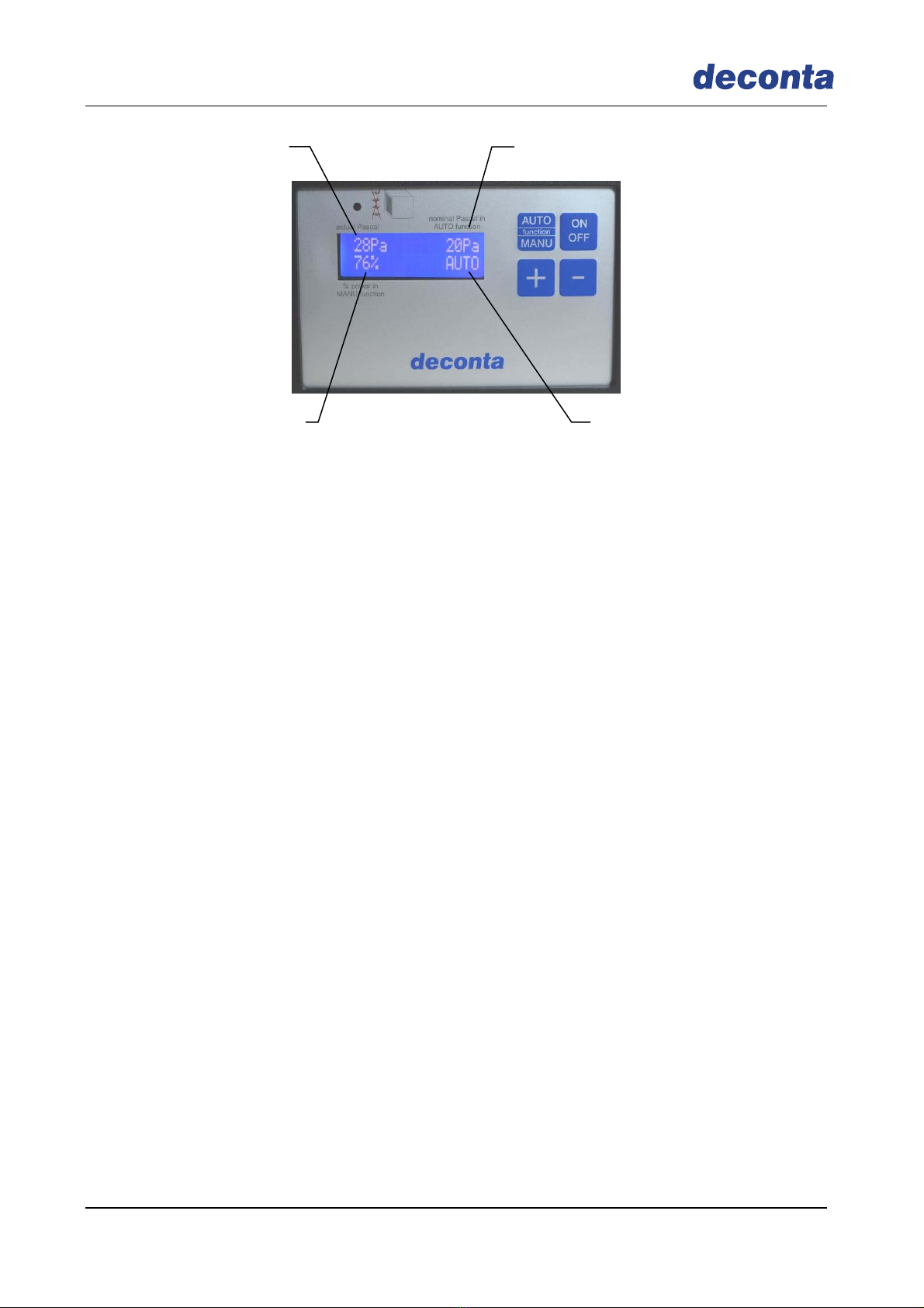
Main switch
Mounted plug
Mains OK
Fan active
Fan ON/OFF
Fan control
Filter control
1. Filter stage
(regenerative Filter)
Filter control
2. Filter stage
(HEPA Filter)
Cleaning active
Operating hours
Com
p
resso
r
Cleaning ON/OFF
Operating hours
Fan
Compressed ai
r
external

Instruction manual
Mobile Deduster ME 12
Version 1 Seite 11
6.1.Option automatic control SRE
The main task of the control unit is to measure and to control the required negative
pressure in the working area.
Specify the measuring point in the working area and connect to the connection
negative pressure with PE-hose 8 x 1
Determine the measuring point in the clean area (adjoining rooms) an connect to
the connection atmosphere with PE-hose 8 x 1
Connection external Compressor
Min. 5 bar / max. 10 bar
Connection
negative pressure
Connection
atmosphere
Instruction manual
Mobile Deduster ME 12
Version 1 Seite 12
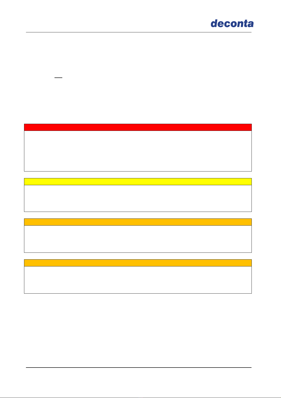
Manual operation:
In manual operation, the „+“ and „-“ keys are used to set the fan performance. The
display show the performance value in „%“ and the measured negative pressure.
Automatic operation:
In automatic mode, the set point in Pascal for the negative pressure is preset with the
keys „+“ and „-„ (display set value in automatic mode). By comparing the entered set
point value with the permanently measured current actual value (measured negative
pressure), the speed of the fan is automatically adapted, that is, the fan moves
automatically „up“ and „down“.
Important:
In the event of power failure, the control saves the last set values, restarts automatically
after damage elimination and restores the saved data.
Set value in automatic operation
Operating mode (AUTO or MANUAL)
Measured negative pressure
Fan performance in %
Instruction manual
Mobile Deduster ME 12
Version 1 Seite 13
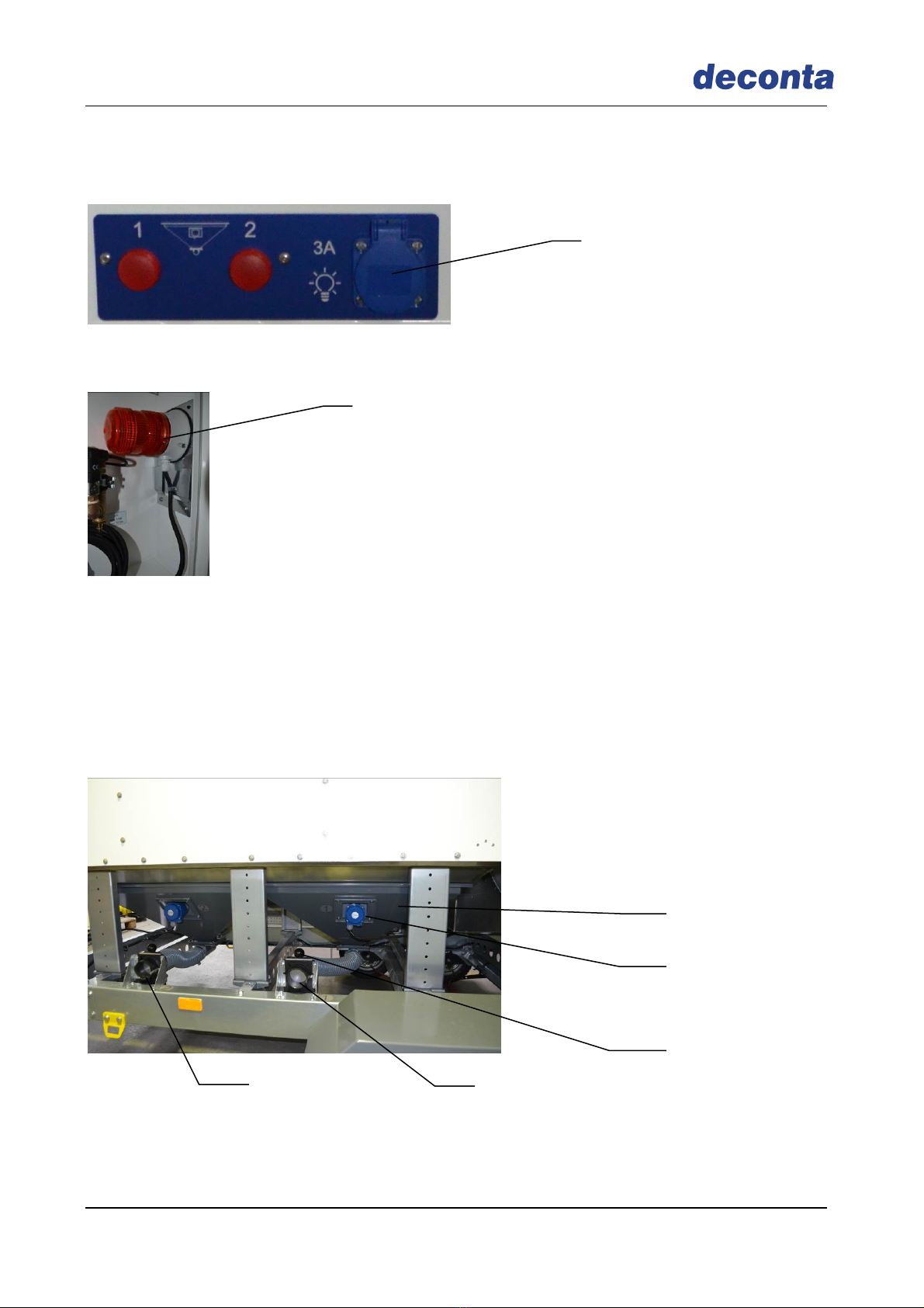
6.2.Option Dust bunker with filling level control and emptying via suction port
A full bunker is indicated by two signal lights on the control unit.
When the bunker is full, the alarm socket is supplied with power. An external signal light
or signal horn can be connected to this alarm socket.
For emptying the bunker, there are 2 suction connections on the unit.
Switch off Fan and Cleaning function of the mobile dust extractor!
Connect the suitable vacuum cleaner to the suction connection
Open shut-off valve
The Bunker can now be vacuumed
Please note!
After emptying, the shut-off valve must be closed again.
Dust bunker
Fill level monitoring
Suction connection 1
Suction connection 2
Shut-off valve
Alarm socket
Signal lamp in
transport mechanism

Instruction manual
Mobile Deduster ME 12
Version 1 Seite 14
7.Maintenance
Maintenance work, including changing/removing filters, may only be carried out by
authorised persons wearing suitable protective clothing.
The appliance must be completely disconnected from the power supply during all repairs
and maintenance work.
We expressly refer to possible additional regional and national regulations in the
maintenance of the appliance technology.
The air-conditioning systems (dust extraction unit, industrial vacuum cleaners and
devices used for venting or negative pressurisation) must be serviced as required, at
least once a year, and checked by a qualified technician. The test result shall be
presented on request.
7.1.Details on filter change
The frequency of the filter change depends on the degree of contamination of the filters.
As the filter occupancy is increased (contamination of the filters), the air performance
decreases.
For filter monitoring during operation, there are two manometers installed on the device.
We recommend a filter change when the “max” mark has been reached.
Important: Only use approved, flawless filters!
7.2.Regular maintenance
Check for air tightness
Check solenoid valves function properly
Check oil level of compressor
Regularly emty dust bunker
After the end of work, release overpressure in pressure accumulator by moving the hand
gear.
Filter control
1. Filter stage
(regenerative Filter)
Filter control
2. Filter stage
(HEPA Filter)

Instruction manual
Mobile Deduster ME 12
Version 1 Seite 15
8.Possible disturbances and their elimination
Disturbance Possible reason Elimination
Unit does not work Power source out of order Have power source repaired by expert
Unit does not work Defective compononents Have unit repaired by deconta or a
workshop authorized by deconta
Cleaning of filter does
not work Plug of solenoid valve
may be loose Insert plug one more time
Compressor does not
run Compressor is not
switched on Remove right front panel und switch
on compressor
Compressor does not
run Plug of compressor came
off Remove right front panel and insert
plug again
Caution!
Work on the unit may only be carried out in a voltage-free state.

Instruction manual
Mobile Deduster ME 12
Version 1 Seite 16
9.Declaration of conformity
EC Declaration of Conformity acc. to Machinery Directive 2006/42 / EC Annex II 1.A
The manufacturer
deconta GmbH
Im Geer 20
46419 Isselburg
hereby confirms that the following product
Product description: mobile dust extraction unit
Type designation: ME 12
Type number: 94, 565
complies with all applicable regulations of the above-mentioned directive and the other applicable
directives (hereafter), including the amendments applicable at the time of the declaration.
The following other EU directives were applied:
EMC directive 2004/108 / EC
The following harmonized standards were applied:
EN 60204-1:2006/AC:2010
EN 60335-2-69:2012
The following national or international standards (or parts / clauses thereof) and specifications were
applied:
DIN VDE 0701-0702 (VDE 0701-0702):2008-06
Place: Isselburg
Date: 14.11.2016
(Wilhelm Weßling)
Director
Table of contents
Other deconta Vacuum Cleaner manuals


