Dectron DRY-O-TRON Supervisaire DS 010 User manual

FOR MODELS
DS DSV DB RS RB
010 010 010
015 015 015
020 020 020
030 030 030
040 040 040 040 040
042 042 042 042 042
050 050 050 050 050
060 060 060 060 060
062 062 062 062 062
080 080 080 080 080
082 082 082 082 082
100 100 100 100 100
102 102 102 102 102
120 120 120 120 120
122 122 122 122 122
150 150 150 150 150
152 152 152 152 152
162 162 162 162
164 164 164 164
182 182 182 182
184 184 184 184
202 202 202 202
204 204 204 204
242 242 242 242
244 244 244 244
282 282 282 282
284 284 284 284
362 362 362 362
364 364 364 364
368 368 368 368
402 402 402 402
404 404 404 404
408 408 408 408
482 482 482 482
484 484 484 484
488 488 488 488
562 562 562 562
564 564 564 564
568 568 568 568
804 804 804 804
808 808 808 808
Dectron, Inc. March 2012
Data subject to change without notice.
1
®
For future reference,
write your model number* here ______________
write your serial number* here ______________
write your ref number* here ______________
*See Product Description - Unit Nameplate.
Design, Installation, Start-Up, and Operation Manual
Arranged by Trades and Tasks
(Attach pages as addenda to contracts & work-orders.)
Contents: Section
Product Description 1
Building Design and Construction 2
Receiving, Unloading, Lifting, & Locating 3
Installation 4
Pre-Assembly 4a
Air Distribution, Ventilation, & Ducts 4b
Piping 4c
Wiring 4d
Testing, Adjusting, and Balancing 5
Startup 6
Operation and Maintenance 7
Service 8
Prg
Esc
Esc
Prg
Supervisaire®CONTROLLER
1

Dectron, Inc. March 2012
DSH/DSV/RSH/DBH/RBH Series Dehumidifier Owner’s Manual
Data subject to change without notice.
2
USER AGREEMENT:
Where any differences exist between the named electronic file obtained directly from Dectron,
Inc. and other versions, the named electronic file shall have precedence. Electronic versions
are subject to validation by Dectron, Inc.
CANADA
DECTRON INC.
4300 Poirier Boulevard
Montreal, QC.
H4R 2C5
Tel.: 514-334-9609 or
1-800-667-6338 or
1-888-DECTRON
U.S.A
DECTRON INC.
10898 Crabapple Road
Suite 103
Roswell, GA 30075
Tel.: 770-649-0102 or
1-800-676-2566
Fax: 770-649-0243
Corresponding Electronic File Name:
DS_SPVR_OM_2012-Mar-27.pdf
NOTE:
For your convenience this manual is organized into tasks arranged in a workable order. Most
material relevant to a single task is on one page or a group of sequential pages.
Please attach copies of the appropriate pages to the task contract or work-order. License is
hereby granted to copy and distribute as appropriate any pages contained herein for the sole
purpose of assisting in the proper application, installation, operation, maintenance, and/or
service of Dectron products only. All other rights are retained by Dectron.
To the Owner:
This manual contains important instructions on designing for, installing, starting, operating, and
maintaining your DRY-O-TRON® and system. Please read the entire manual carefully and if you
have any questions contact your local Dectron representative.
Your warranty is valid only if conditions explained in this manual are met.
To the Installer:
This manual contains vital instructions for installing and starting up the DRY-O-TRON® and
system. Please read the entire manual carefully and if you have any questions contact your local
Dectron representative. Your customer’s satisfaction is at stake and the DRY-O-TRON® warranty
may be void if conditions explained in this manual are not met.
Heating, Cooling, or Dehumidifying Construction Sites
The DRY-O-TRON®unit is not a convenience air conditioner. Its capacity is carefully
matched to the expected load. Errors of installation, damage to the unit, and other
performance reductions will be obvious once the building begins normal use.
Never use the unit to heat, cool, or dehumidify a construction site. The air coils must be
protected against construction dusts until all construction dusts have been removed from the
space, and from the outdoor-air intake (if any). Construction dusts bind to the cooling coil
permanently and cannot be removed. Once bound, the dusts reduce heat transfer and airflow
rate. Filters will not prevent this.
The resulting performance reduction and possible component damage are not covered by
the Dectron warranty.
2

Page
Safety 4
Product Description 1.1
Major Airflow Options 1.5
Unit Nameplate Information 1.11
Building Construction 2.1
Safety 2.2
Moisture Migration & Required Vapor Retarder 2.4
Door and Window Design 2.5
Component Overview 2.6
Space Heating and Cooling Availability 2.8
Outdoor-Air Intake 2.9
Air-Handler Location 2.10
Condenser or DryCooler Location 2.12
Maximum Refrigerant-Tube Length 2.13
Ducts 2.14
Fire / Smoke Detectors 2.21
Air Distribution 2.22
Supply Diffuser Proximity and Aiming 2.29
Fabric Duct 2.30
Pool-Chemical Storage Facility 2.31
Pool-water Chemistry 2.32
Receiving, Unloading, Lifting, and Locating
Safety 3.2
Air Handler
Select Air Handler Location 3.4
Nameplate Information 3.4
O/A Intake Clearances 3.5
Flue and Exhaust Clearances 3.5
Minimum Service Clearances 3.6
Door Clearances 3.7
Unit Support 3.9
Vibration Isolation 3.9
Underside Piping 3.10
Overhead Installation 3.11
Lifting Air Handler 3.12
Remote Condenser or DryCooler
Select Location 3.14
Vibration Isolation 3.16
Lifting 3.17
Installation 4.1
Safety 4.2
Component Overview 4.4
Air Distribution 4b.1
Ducts 4b.11
Standard Practice 4b.12
Determine Allowable O/A Flow 4b.14
Standard Supply-Air Flows 4b.15
Ducting Parallel Units 4b.16
Return-Duct Requirements 4b.17
Return Grille Location 4b.19
Construction Dust 4b.20
Supply-Duct Requirements 4b.21
Supply-Duct Heater 4b.21
Outdoor-Air Duct 4b.23
Ventilation Systems 4b.24
Exhaust Duct 4b.28
Checklist 4b.29
Page
Piping
Safety 4c.1
Refrigerant Piping 4c.4
General Piping 4c.16
Cooling Water 4c.18
Heating Water 4c.21
Condensate Drain 4c.22
Pool Water 4c.23
Checklist 4c.27
Wiring
Safety 4d.1
Power 4d.4
Control Signals 4d.11
Checklist 4d.33
Test, Adjust, and Balance
Safety 5.2
Determine Damper Types 5.11
Apply Electric Power 5.13
Controller Interface 5.14
(NO LINK) Interface Addressing 5.15
Set Air Dampers 5.16
Enable Blower(s) 5.19
Determine Allowable Outdoor-Air Intake Rate 5.27
Test, Adjust, and Balance Airflows 5.28
Test Adjust, and Balance Water Flows 5.30
Checklist 5.38
Startup 6.1
Safety 6.2
Pre-Startup Adjustments 6.4
Pre-Startup Checklist 6.8
Controller Interface 6.13
Enable Operation 6.22
Adjustments 6.26
Instructions for Warranty Registration 6.36
Warranty Registration 6.37
Operation 7.1
Safety 7.2
Maintenance 7.4
Maintenance Record 7.5
Air Filters 7.7
Pool Chemistry 7.19
Heating and Cooling Availability 7.20
Logical Flow Charts 7.21
Controller Interface 7.25
User Interface Map 7.26
Read Status Messages 7.28
Set-Point Adjustments 7.30
Warranty 7.32
Service 8.1
Safety 8.2
Alarms 8.4
Sensor Curves 8.22
Other Possible Problems 8.23
Closing Manual Valves 8.33
Display Contrast 8.34
Dectron, Inc. March 2012
Owner’s Manual DSH/DSV/RSH/DBH/RBH Series Dehumidifier
Contents
Data subject to change without notice.
3
3

WARNING
Dectron, Inc. March 2012
DECTRON
DSH/DSV/RSH/DBH/RBH Series Dehumidifier Owner’s Manual
Safety Warnings
Data subject to change without notice.
4
Save this manual and refer to it whenever a question arises. This manual contains important safety information.
Read the entire manual first, then follow the instructions for designing for, installing, starting, and/or operating this
product.
Follow any safety, warning,operating, or instructional labels on and inside the product.
Do not attempt to move, install, or service this product unless you are qualified to do so.
Risk of electric shock. Can cause injury or death.
Some installation and service procedures could expose personnel to the risk of
electric shock. Electric shock can cause injury or death.
The unit controller does not disconnect electrical energy from the unit, even in the
OFF condition. Use only approved devices (e.g. locking safety switch), to disconnect,
lockout, and tagout all sources of electrical energy before working inside the unit
cabinet. Follow all applicable safety regulations.
Risk of explosive pressure release. Can cause injury or death.
This product contains refrigerant liquid and vapor under high pressure. Some
installation and service procedures could expose personnel to the risk of explosive
discharge. Some installation and service procedures could expose personnel to the
risk of frostbite from release of refrigerant.
Reclaim refrigerant to reduce the pressure to atmospheric before working on pipes,
valves, heat exchangers, compressors, pressure switches, etc.
Once opened, do not close any manual refrigerant valves that might isolate
refrigerant from the relief valve. If necessary, install relief valves (by others).
Risk of contact with moving parts. Can cause injury or death.
This product contains rotating parts and V-belt drives. Some installation, service,
and maintenance procedures could expose personnel to the risk of injury or death
from contact with these parts.
Using only approved devices (e.g. locking safety switch), disconnect, lockout, and
tagout all sources of electrical energy before working inside the unit cabinet. Allow
adequate time for rotating parts to stop. Follow all applicable safety regulations.
Do not operate the unit until ductwork or a screen is installed at each blower
outlet.
Risk of top-heavy units tipping over. Can cause property damage, injury, or death.
Some units and some ancillary equipment may be shipped in crates that are top
heavy. Follow the instructions in the Lifting and Locating section, along with all
appropriate codes and procedures.
Vertical units may be top-heavy even after removal from shipping materials. Follow
the instructions in the Lifting and Locating section, along with all appropriate codes
and procedures.
WARNING
Risk of flying liquids, gases, particles. Can cause eye injury.
Many tasks involve risk of exposure to flying materials which can cause eye injury.
Always wear protective safety glasses or goggles, as appropriate.
WARNING
WARNING
WARNING
DESCRIPTION
4

Dectron, Inc. March 2012
DECTRON
Owner’s Manual DSH/DSV/RSH/DBH/RBH Series Dehumidifier
Warnings
Data subject to change without notice.
5
Risk of falling. Can cause injury or death.
Depending on the size and location of this product, some installation, service, and
maintenance procedures could expose personnel to the risk of injury or death by falling.
Designs should include adequate service and maintenance access. Use fall-
protection equipment as appropriate.
Risk of contact with hot surfaces. Can cause injury.
This product contains surfaces which can cause burn injury.
The compressor, refrigerant-discharge tubes, and heat exchangers can become
extremely hot during operation.
Compressor crankcase heaters can be extremely hot at any time.
Turn off the unit and allow time for these parts to cool before working inside the unit
cabinet. Wear protective clothing (gloves, sleeves, etc.) while working on these parts.
Risk of leaking water. Can cause property damage.
This product may use circulating water under pressure.
This product requires a free-flowing drain.
Freezing or other abnormal conditions could cause leakage or overflow.
Uncontrolled water can cause expensive damage to buildings and other equipment.
Do not locate this product above any equipment that could be damaged by water.
Risk of contamination of breathing air. Can cause injury or death.
Application of this product may involve the intake of outdoor air. The point of intake
must be carefully chosen to prevent intake of contaminants.
Application of this product may involve air-handling equipment, e.g. ducts, cabinets,
plenums, etc., which operate below atmospheric pressure. Such equipment must be
carefully located and installed to prevent the intake of contaminants.
Follow the instructions in this manual and all applicable codes.
NOTICE
NOTICE Risk of uncontrolled condensation. Can cause property damage.
This product is intended to control relative humidity and temperatures. Improper
design, installation, and/or operation can lead to uncontrolled condensation of water,
with associated property damage.
Read and follow the instructions in this manual. Optional material will be noted as
being optional. All other material should be considered as important to the proper
function of the product.
WARNING
WARNING
CAUTION
DESCRIPTION
5

Dectron, Inc. March 2012
DSH/DSV/RSH/DBH/RBH Series Dehumidifier Owner’s Manual
Data subject to change without notice.
6
Product Description
DESCRIPTION
DRY-O-TRON®is the original energy recycling
dehumidifier. Tens of thousands of units have
been installed throughout the world, and DRY-
O-TRON®has become synonymous with qual-
ity, reliability and energy savings.
Dectron Inc., the inventor of DRY-O-TRON®, is
a company committed to being the absolute
best at what they do - providing leading expert-
ise and quality products to customers who
need to control high humidity efficiently.
Today’s DRY-O-TRON®represents years of
intensive research and development by a team
of highly qualified experts. Dectron has the
only large-scale dehumidifier testing and envi-
ronmental simulation laboratory in the industry.
Every DRY-O-TRON®model line has been
developed in this laboratory, and every cus-
tomer’s unit is factory tested before shipment.
The DRY-O-TRON®is available in a broad
range of standard products for industrial and
commercial applications. We also have a team
of highly skilled engineering and manufacturing
professionals who are dedicated to custom
design projects.
DRY-O-TRON®DS Series
Energy-Recycling
Dehumidifiers and
Water Heaters for
Indoor Pools,
Whirlpools and Spas
1.1

Dectron, Inc. March 2012
Owner’s Manual DSH/DSV/RSH/DBH/RBH Series Dehumidifier
Data subject to change without notice.
Product Description
Your DRY-O-TRON®energy
recycling dehumidifier and water
heater is a precision engineered
product, finely tuned to the condi-
tions in your natatorium to
achieve maximum performance
and energy savings.
Your DRY-O-TRON®has been
tested at our factory by skilled
personnel. The installation of this
state-of-the-art equipment must
be performed by an experienced
heating, ventilation and air condi-
tioning (HVAC) technician, who
has been trained by Dectron.
IMPORTANT!
The DRY-O-TRON®is one of
several key components in
your natatorium environment
control system. In order for
your natatorium to be comfort-
able and condensation free the
following areas must be
addressed by you and your
contractor, engineer and archi-
tect design team:
ΔΔHumidity control
ΔΔAir distribution
ΔΔDuct design
ΔΔVentilation requirements
ΔΔMoisture migration
ΔΔPool water chemistry
A humidity control system will
not provide the expected com-
fort level and building protec-
tion if any of these are over-
looked.
Dectron provides guidelines
(included in this manual) for each
of these critical areas. These
guidelines have been devel-
oped from years of field experi-
ence and should be strictly
adhered to or there is a good
chance that your system will
not work as expected. It is the
responsibility of the owner and
his design team (contractor, engi-
neer and architect) to ensure that
careful consideration has been
given to all of the aspects of
natatorium environment control.
At Dectron, we care about how
you protect your investment.
The DS Series
ΔRecycles energy
ΔSaves up to 80% of the energy
costs associated with indoor
pools and spas
ΔHelps protect against building
damage resulting from uncon-
trolled humidity
ΔHeats the pool water (See
ventilation limitations under
Major Airflow Options and
under Building Construction-
Outdoor-Air Intake.)
ΔMaintains relative humidity
levels between 50 and 60% -
Guaranteed!
ΔCan provide year round
comfort with optional air
conditioning
ΔContributes to space heating in
cold weather
The DRY-O-TRON®DS Series
When properly installed accord-
ing to Dectron’s instructions, the
DRY-O-TRON®will give years of
trouble-free comfort, energy sav-
ings and building protection.
The DRY-O-TRON®features a
unique patented simultaneous
energy recycling system. Only
DRY-O-TRON®can heat air and
water continuously and at the
same time with recycled energy
to provide ultra-smooth control
over space conditions. This
means a more comfortable envi-
ronment for the bather. Water and
air temperatures are always
maintained close to their set
point, while relative humidity lev-
els are kept to a comfortable 50-
60%. DRY-O-TRON®can also be
equipped with optional air condi-
tioning for year round space tem-
perature control.
Dectron is the only manufacturer
of energy recycling dehumidifiers
that will guarantee pool water
temperature and space relative
humidity conditions, in writing.
Dectron stands behind their
product!
DRY-O-TRON®dehumidifiers
features standard microprocessor
control. For the owner this
means precise automatic control,
high reliability, and ease-of-use.
For the installer and service
person this means simpler
installation and start-up with
built-in diagnostics and
troubleshooting in the unlikely
event that service is required.
Dectron uses state-of-the-art
computer design and model
selection programs which incor-
porate ASHRAE ventilation
requirements to design the right
DRY-O-TRON®system for every
application.
DESCRIPTION 7
1.2

How the DRY-O-TRON®Works
In the natatorium, there is a
vapor pressure difference
between the pool water and the
enclosure air. This produces
continuous evaporation of pool
water, resulting in high humidity
conditions and a steady drop in
pool water temperature if left
uncontrolled. The high humidity
can result in serious building
decay, and the pool water
requires virtually continuous
heating.
An earlier practice called for
exhausting the humid air, replac-
ing it with outdoor air which had to
be heated to room temperature.
In addition, a full size pool heater
was required to maintain pool
water temperature. This
procedure was costly and wasted
energy as well.
The heat lost by the pool when
evaporation takes place is
actually “trapped” by the moisture
in the air. A DRY-O-TRON®unit is
engineered to capture this
trapped energy, and to recycle it
back to the pool where it came
from! This energy recycling can
save up to 80% of the cost of
heating your pool by earlier
methods. Now you can protect
your investment from humidity
damage, provide a comfortable
environment for bathing, and
save money at the same time!
You can also feel good about
making your contribution to the
environment by using recycled
energy.
The DRY-O-TRON®
dehumidifiers have been
specifically designed to offer a
complete solution for natatorium
environment control. In
DRY-O-TRON®units, cooling is
used to produce from moist air:
ΔΔComfortable, dry supply air
ΔΔTotal heating requirement for
pool water
ΔΔCondensate (returned to the
pool if desired, reducing make-
up water requirements.)
The energy cycle of this process
has an efficiency of 100% since
all moisture or latent heat is con-
verted into sensible heat for
recycling. The electrical energy
required to operate the system is
also converted into sensible heat
and contributes to space heating.
In the DRY-O-TRON®, warm
humid air passes through the
dehumidifying coil and is cooled
below its dew point, thereby con-
densing moisture. The heat cap-
tured by this process is combined
with the heat generated from the
compressor power consumption.
This recovered heat is then avail-
able for recycling. The DRY-O-
TRON®is the only system on the
market which can simultaneously
and continuously recycle this
recovered energy into:
ΔΔHeating the supply air. The
leaving supply air dry bulb
temperature is always the
same or higher than the
entering return air (except
during cold pool water start-up
and when the air-conditioning
option is in use).
A built-in automatic compen-
sation system permits unit startup
regardless of water temperatures.
During initial start-up with low
pool water temperature, all avail-
able heat is directed to the pool
water. Once the desired tempera-
ture is reached, the water heating
system adjusts its output auto-
matically.
The DRY-O-TRON®’s capability
of simultaneously and continu-
ously recycling heat to air and
water ensures a more stable
natatorium environment.
DRY-O-TRON®units are avail-
able in a number of configura-
tions which will easily accept the
introduction of controlled quanti-
ties of outdoor air. DRY-O-TRON®
models DS 40 and larger are
equipped with a standard make-
up air intake which will allow up to
15% outdoor air.
Dectron, Inc. March 2012
DSH/DSV/RSH/DBH/RBH Series Dehumidifier Owner’s Manual
Product Description
Data subject to change without notice.
8DESCRIPTION
1.3

Dectron, Inc. March 2012
DECTRON
Owner’s Manual DSH/DSV/RSH/DBH/RBH Series Dehumidifier
Data subject to change without notice.
9
Features
ΔΔStandard operator panel
ΔΔEnergy efficiency
ΔΔLittle maintenance required
ΔΔSimple operation
ΔΔSimple installation
ΔΔThe basic Dectron DS series DRY-O-TRON®units
offer dehumidification of natatorium air as well as pool
water heating. The optional Cooling mode offers space
cooling.
ΔΔThe DS series DRY-O-TRON®unit controls an aux-
iliary pool water heater as necessary to maintain pool
water temperature.
ΔΔAn optional hot-water heating system is available to
make use of a building boiler system for heating. This
factory modification must be ordered at time of pur-
chase.
ΔΔDS series DRY-O-TRON®units are supplied with
heat exchangers, air filter(s), and all controls.
ΔΔAn optional outdoor air intake system includes an
automatic damper to stop the outdoor airflow during
unoccupied periods.
ΔΔA microprocessor control system automatically
determines the proper operating mode, based on con-
ditions and occupation. A simple connection to building
management systems is available.
ΔΔEnergy consumption
The DS DRY-O-TRON®series offers a temperature
and humidity monitoring system that insures the unit is
working only as necessary. Automatic refrigeration
staging in the remote condenser matches the system
capacity to the load. Energy consumption is always
minimized.
Horizontal Configuration
Vertical Configuration
DESCRIPTION
Product Description
Sample
Appearance may vary.
Sample
Appearance may vary.
1.4

Product Description Major Airflow Options
DECTRON
Dectron, Inc. March 2012
DSH/DSV/RSH/DBH/RBH Series Dehumidifier Owner’s Manual
Data subject to change without notice.
10
Basic DRY-O-TRON®
The basic DRY-O-TRON®controls the humidity in
the space and returns to the pool the heat it has lost
to evaporation.
The same amount of return air passes through the
evaporator and the evaporator bypass.
The outdoor-air intake flow rate can be up to 15%
of the total supply airflow rate, or up to 35% if the
unit has the air-conditioning option, depending on
outdoor temperature. The incoming outdoor air
must be heated (by others) to not less than 32°F
(0°C). There may be limitations on maximum flow
rates. See subsequent page in this manual.
Any unit with more than 15% outdoor air must have an auxiliary pool heater, which may be by others.
A built-in clock may limit the intake of outdoor air and/or the exhaust of room air to occupied periods only.
DRY-O-TRON®with Economizer
The economizer reduces the amount of energy
required for cooling by using a full flow of outdoor
air when possible.
The same amount of return air passes through
the evaporator and the evaporator bypass.
Under normal (not economizer) mode the
outdoor-air intake flow rate can be up to 15%
(or up to 35% with air-conditioning option) of the
total supply airflow rate, depending on outdoor
temperature.
Except in economizer mode, the incoming
outdoor air must be heated (by others) to not less
than 32°F (0°C). There may be limitations on
maximum flow rates. See subsequent page in
this manual.
In order to maintain a negative pressure on the
natatorium, the exhaust airflow rate should be 110% of the outdoor air intake flow rate.
When outdoor air conditions permit, the refrigeration system is automatically stopped and the room exhaust
air and outdoor air intake flow rates are varied to control temperature.
The outdoor-air intake damper(s) must be adjusted mechanically to limit the intake flow to maintain a slight
negative pressure on the room.
Natatoriums with DRY-O-TRON®units having the Economizer option must also have auxiliary pool heaters,
which may be by others.
Some units with the economizer option may also be equipped with the Intelligent Energy Saver option.
The Intelligent Energy Saver®economizer reduces the amount of energy required for cooling and for
dehumidification by using an increased flow of outdoor air when possible. A preset amount of outdoor air is
brought in during occupied periods, and is increased only as necessary for dehumidification or cooling.
For more information on the Economizer option, refer to Appendix M5 - Economizer.
RETURN AIR
COOLING COIL REHEAT COIL
SUPPLY BLOWER
RETURN-AIR
FILTERS
BYPASS DAMPER
OUTDOOR-AIR
FILTERS OUTDOOR-AIR DAMPER
SUPPLY AIR
OUTDOOR AIR
RETURN AIR
COOLING COIL REHEAT COIL
SUPPLY BLOWER
RETURN-AIR BLOWER MIXING DAMPER
RETURN-AIR
FILTERS
BYPASS DAMPER SUPPLY-AIR FILTERS
OUTDOOR-AIR DAMPER
EXHAUST-AIR DAMPER
SUPPLY AIR
OUTDOOR AIR
EXHAUST AIR
DESCRIPTION
1.5

DECTRON
DRY-O-TRON®with SmartSaver®
The SmartSaver®exchanges heat from the
exhaust air to the incoming outdoor air to save
heating energy. A heat pipe or a thermo-siphon
system is installed between the exhaust air and
the outdoor air intake. When the outdoor air is
colder than the room exhaust air, the
SmartSaver®recovers heat from the exhaust
stream and delivers it to the outdoor air intake.
The same amount of air passes through the
bypass and the evaporator.
The normal occupied-period outdoor-air intake
flow rate can be up to 15% of the total supply
airflow rate, or up to 35% if the unit has the
air-conditioning option. Units with the
SmartSaver option do not require incoming
outdoor air to be heated, as long as the incoming
outdoor air is above -20°F (-29°C).
Any unit with more than 15% outdoor air
must have auxiliary pool heat, which may be by others.
The exhaust airflow rate should be 110% of the outdoor air intake flow rate.
For more information, refer to Appendix M3 - SmartSaver.
SUPPLY AIR
EXHAUST AIR
OUTDOOR AIR
OUTDOOR AIR
COOLING COIL REHEAT COIL
SUPPLY
BLOWER
RETURN-AIR
FILTERS
EXHAUST-AIR
FILTERS
SMARTSAVER
EVAPORATOR
MINIMUM EXHAUST BLOWER
MINIMUM EXHAUST DAMPER
BYPASS DAMPER
SMARTSAVER FILTERS
MINIMUM O/A DAMPER
SMARTSAVER CONDENSER
RETURN
AIR
DRY-O-TRON
®
Glycol SmartSaver®
The SmartSaver®exchanges heat between the
exhaust air and the incoming outdoor air to save
energy. A pumped-glycol heat-exchange system is
installed between the exhaust air and the outdoor
air intake. When the outdoor air is colder than the
room exhaust air, the SmartSaver®recovers heat
from the exhaust stream and delivers it to the
outdoor air intake stream. When the outdoor air
is warmer than the room exhaust air, the
SmartSaver®removes heat from the outdoor air
intake stream and delivers it to the exhaust
air stream.
The same amount of air passes through the
bypass and the evaporator.
The normal occupied-period outdoor-air intake flow
rate can be up to 15% of the total supply airflow rate,
or up to 35% if the unit has the air-conditioning option. Units with the SmartSaver option do not
require incoming outdoor air to be heated, as long as the incoming outdoor air is above -20°F (-29°C).
Any unit with more than 15% outdoor air must have auxiliary pool heat, which may be by others.
For more information, refer to Appendix M3 - SmartSaver.
Dectron, Inc. March 2012
Owner’s Manual DSH/DSV/RSH/DBH/RBH Series Dehumidifier
Major Airflow Options Product Description
Data subject to change without notice.
11
SUPPLY AIR
EXHAUST AIR
OUTDOOR AIR
OUTDOOR AIR
COOLING COIL REHEAT COIL
SUPPLY
BLOWER
RETURN-AIR
FILTERS
EXHAUST-AIR
FILTERS
SMARTSAVER
EVAPORATOR
GLYCOL PUMP
MINIMUM EXHAUST BLOWER
MINIMUM EXHAUST DAMPER
BYPASS DAMPER
SMARTSAVER FILTERS
MINIMUM O/A DAMPER
SMARTSAVER CONDENSER
RETURN
AIR
DESCRIPTION
1.6

EconoPurge Option
Units equipped with the Purge option may also be
equipped to maximize energy conservation with a
variation of economizer or Intelligent Energy Saver
options.
If the unit is equipped with an outdoor-air temperature
sensor, the Purge mode described above may also
operate automatically during periods when the outdoor
air is cool enough to control room temperature by
ventilation alone. This mode is one of the
economizer options.
If the unit is equipped with both outdoor-air
temperature sensor and an outdoor-air humidity
sensor, then the Purge mode described above may
also operate automatically when the outdoor air is cool
and dry enough to control room temperature and/or rel-
ative humidity by ventilation alone. This mode is one of
the the Intelligent Energy Saver options.
The outdoor-air intake damper(s) must be adjusted
mechanically to limit the intake flow to maintain a slight
negative pressure on the room.
Dectron, Inc. March 2012
DSH/DSV/RSH/DBH/RBH Series Dehumidifier Owner’s Manual
Product Description Major Airflow Options
Data subject to change without notice.
12
DECTRON
SUPPLY AIR
OUTDOOR AIR
OUTDOOR AIR
COOLING COIL
FACE DAMPER REHEAT COIL
SPACE HEATER
SUPPLY
BLOWER
RETURN-AIR
FILTERS
MINIMUM EXHAUST BLOWER
MAXIMUM EXHAUST DAMPER
MINIMUM EXHAUST DAMPER
MAXIMUM EXHAUST BLOWER
BYPASS DAMPER
MINIMUM O/A DAMPER
PURGE DAMPER
SUPPLY FILTERS
RETURN
AIR
EXHAUST AIR
SUPPLY AIR
OUTDOOR AIR
OUTDOOR AIR
COOLING COIL
FACE DAMPER
SUPPLY
BLOWER
RETURN-AIR
FILTERS
MINIMUM EXHAUST BLOWER
MAXIMUM EXHAUST DAMPER
MINIMUM EXHAUST DAMPER
MAXIMUM EXHAUST BLOWER
BYPASS DAMPER
MINIMUM O/A DAMPER
PURGE DAMPER
SUPPLY FILTERS
RETURN
AIR
REHEAT COIL
SPACE HEATER
EXHAUST AIR
EXHAUST AIR
Normal operation
Purge Mode
DRY-O-TRON®with
Purge Option
Superchlorination of a pool may produce
gases and odors that preclude the presence
of swimmers in the natatorium. Purge mode
may be controlled manually to minimize the
time in which people must be out of the
natatorium during superchlorination.
On receipt of a manual input from the
operator,
1. the refrigeration system is stopped,
2. the supply blower continues to run,
3. the evaporator face dampers close,
4. the evaporator bypass damper closes,
5.
the outdoor-air damper opens completely,
6. the dampers for blower EF2 open, and
7. EF2 (the larger exhaust blower) runs.
Under normal conditions, half the return
air passes through the evaporator while the
other half passes through the bypass.
Under normal (not Purge) mode the
outdoor-air intake flow rate can be up to
15% (or up to 35% with air-conditioning
option) of the total supply airflow rate,
depending on outdoor temperature.
Except in Purge mode, the incoming outdoor
air must be heated to not less than
32°F (0°C). Theremay be limitations on
maximum flow rates. See subsequent page
in this manual.
Natatoriums with DRY-O-TRON®units
having the Economizer option must also
have auxiliary pool heaters, which may be
by others.
For more information, refer to
Appendix M6 - Purge.
DESCRIPTION
1.7

DECTRON
Dectron, Inc. March 2012
Owner’s Manual DSH/DSV/RSH/DBH/RBH Series Dehumidifier
Major Airflow Options Product Description
Data subject to change without notice.
13
RETURN AIR
COOLING COIL
REHEAT COIL
SUPPLY BLOWER
RETURN-AIR
FILTERS
BYPASS DAMPER
OUTDOOR-AIR DAMPER
SUMMER
EXHAUST-AIR
DAMPER
WINTER
EXHAUST-AIR
DAMPER
SUPPLY AIR
OUTDOOR AIR
EXHAUST AIR
RETURN
AIR
RETURN AIR
COOLING COIL
REHEAT COIL
SUPPLY BLOWER
RETURN-AIR
FILTERS
BYPASS DAMPER
OUTDOOR-AIR DAMPER
SUMMER
EXHAUST-AIR
DAMPER
WINTER
EXHAUST-AIR
DAMPER
SUPPLY AIR
OUTDOOR AIR
EXHAUST AIR
RETURN
AIR
DRY-O-TRON®with
EconoSaver®
The EconoSaver®reduces the amount of
energy needed for heating by recovering heat
with the refrigeration system.
In the summer, room air is exhausted
directly. In winter mode, cold air from the
evaporator is exhausted. The heat removed
from the exhaust air is returned to the
incoming outdoor air in the reheat heat
exchanger. This reduces the energy needed
for heating.
The same amount of return air passes
through the evaporator and the evaporator
bypass.
The outdoor-air intake flow rate can be up
to 15% (or up to 35% with air-conditioning
option) of the total supply airflow rate,
depending on outdoor temperature. The
incoming outdoor air must be heated (by
others) to not less than 32°F (0°C). There
may be limitations on maximum flow rates.
See subsequent page in this manual.
DESCRIPTION
1.8

DECTRON
Dectron, Inc. March 2012
DSH/DSV/RSH/DBH/RBH Series Dehumidifier Owner’s Manual
Data subject to change without notice.
There are many options for duct connections. In many cases, these options can simplify duct work and lead to
better airflow and better performance.
Some options are illustrated here. Other options are available. Contact your Dectron representative.
For outdoor units, suitable hoods are provided for outdoor air and exhaust air (if any).
Horizontal Units, Return-Air Connections,
Optional at Time of Sale Horizontal Units, Supply-Air Connections
Optional at Time of Sale
Horizontal Units, Outdoor-Air Connections
Optional at Time of Sale (May be linked to other options.) Horizontal Units, Exhaust-Air Connections
Optional at Time of Sale (May be linked to other options.)
DESCRIPTION
Samples
Appearance may vary.
NOTICE Optional Equipment - Some vertical units may have selectable supply-air discharge ports.
Product Description Available Air Connections
14
1.9

Dectron, Inc. March 2012
Owner’s Manual DSH/DSV/RSH/DBH/RBH Series Dehumidifier
Available Air Connections Product Description
Data subject to change without notice.
DESCRIPTION
Samples
Appearance may vary.
Samples
Appearance may vary.
DECTRON
The standard supply-air discharge for vertical units (model DSV-
xxx) is vertically upward.
Some vertical units may have field-selectable ports allowing
supply air to exit through the top or right side. Where this is the
case, select the best port for the installation. It may be possible
to eliminate an otherwise-required duct elbow near the unit.
Cover the unused port with the blank cover.
Other adjustments, including adjustments to the blower, may be
necessary. Open the front-middle access panel and/or the rear-
top access panel to view the blower arrangements. Be sure air
will flow in the proper direction.
Some vertical units with plenum blowers may be equipped with a plenum.
In this case, there may be several field-selectable ports for supply air.
Choose the port (or ports) that allows the best duct routing. Close the other
ports with the included covers.
The plenum of some vertical units may be removable. This may
facilitate moving the unit through tight clearances.
To remove the plenum, open the access panel and disconnect the motor or
the variable-frequency drive (if so equipped). Remove and retain the
mounting screws. Carefully remove the plenum, setting it aside in a
protected area.
When the unit is in its final position, re-assemble the plenum, fastening it in
place with the mounting screws. Re-connect and torque the wires to the
blower or drive.
It may be possible to re-locate the plenum of some vertical units for more
choices of supply-air direction. In this case, remove the plenum as
described above. Remove the side panel and use it to close the top of the
unit. Mount the plenum where the side panel was. (See the illustrations
below.) Re-route the blower wires and re-connect them.
NOTICE Optional Equipment - Some vertical units may have selectable supply-air discharge ports.
Return Air
Outdoor
Air
Supply Air
Supply Air
Return Air
OutdoorAir
Return Air
OutdoorAir
Return Air
OutdoorAir
Supply Air
Supply Air
Supply Air
Supply Air
Supply Air
Supply Air
Supply Air
Supply Air
Supply Air
Supply Air
Supply Air
Supply Air
15
1.10

Dectron, Inc. March 2012
DSH/DSV/RSH/DBH/RBH Series Dehumidifier Owner’s Manual
Data subject to change without notice.
16
Product Description Unit Nameplate
DESCRIPTION
Model Nomenclature:
ixxx-sss-v
nominal voltage
2 = 208V, 1Φ, 60 Hz
3 = 230V, 1Φ, 60 Hz
4 = 208-230V, 1Φ, 60 Hz
5 = 208-230V, 3Φ, 60 Hz
6 = 230V, 3Φ, 60 Hz
7 = 460V, 3Φ, 60 Hz
8 = 575V, 3Φ, 60 Hz
9 = 208V, 3Φ, 60 Hz
Configuration
BH = natatorium dehumidifier, economizer, horizontal
SA = natatorium dehumidifier, skid only, no blower
SB = natatorium dehumidifier, skid only, with blower
SF = natatorium dehumidifier, field-assembled
SH = natatorium dehumidifier, horizontal
SPA = natatorium dehumidifier, field-assembled, no blower
SPB = natatorium dehumidifier, field-assembled, with blower
SV = natatorium dehumidifier, vertical
nominal moisture
removal capacity in
lbs./hr.
D = indoor cabinet
R = outdoor cabinet
DRY-O-TRON ®
MODEL #:
SERIAL #:
I.D. D
ELECTRICAL RATING 460 V ac, 3 ph, 60 Hz
COMPRESSOR
LRA RLA
COMPRESSOR
LRA RLA
COMPRESSOR
LRA RLA
COMPRESSOR
LRA RLA
BLOWER MOTOR HP FLA
BLOWER MOTOR HP FLA
BLOWER MOTOR HP FLA
COND. FAN MOTOR HP FLA
COND. FAN MOTOR HP FLA
PUMP MOTOR HP FLA
ENTHALPY MOTOR HP FLA
ELECTRIC HEATER kW A
Max. L.A.T. (°F)
SERVICE POWER
SPACE HEATING COIL
PSIG Max.
MCA A MAX. FUSE/CKT. BKR.* 15 A
*(HACR type per NEC)
R-22 FACTORY CHARGE lbs
AIR VOLUME CFM
BELT SIZE
WIRING DIAGRAM
REFRIGERANT DESIGN PRESSURES: HIGH/LOW 300/150 PSIG
COMFORMS TO ANSI/UL STD 1995
CERTIFIED TO STD CAN/CSA-
C22.2 NO. 236
LR 45671
FABRIQUÉ AU CANADA / MADE IN CANADA
REF.:
POOL # 1: ft² POOL # 3: ft²
E.W.T.: °F E.W.T.: °F
POOL # 2: ft² POOL # 4: ft²
E.W.T.: °F E.W.T.: °F
AIR TEMP.: °F R.H.: %
R-22 TOTAL SYSTEMCHARGE: lbs
OIL TO BE ADDED AT START-UP: oz
OIL TYPE:
MAX. LENGTH OF REF. LINES (ONE WAY) ft
BETWEEN D.O.T. & REMOTE CONDENSER:
LINE SIZE:
AIR COOLED COND. MODEL #: HOT GAS: in
LIQUID: in
50379
CSA and ETL Label
Operating conditions: Make sure
unit is operating within these con-
ditions. Unit has been selected
and sized accordingly.
Nameplate specifications supersede any other specifications
or statements found in this manual.
For units with air-cooled air-conditioning, the tubes connecting
the DRY-O-TRON®to the remote condenser must be exactly
as shown here. Consult Dectron before exceeding the maxi-
mum length of tube or changing the tube diameters.
At installation, add type and amount of refrigeration oil as shown.
If assistance is needed, have
model, serial number, and Ref.
number (below) before calling.
Important branch circuit information
Component specifications.
Replace with belt of
same type and size
when necessary.
Adjust supply-airflow to
this value ±10%.
Ref number
For units with air-cooled air
conditioning, subtract the amount of
refrigerant given by “Factory Charge”
from the amount given by “Total
System Charge”. The difference must
be added to the DRY-O-TRON®at
installation. See Installation - Piping -
Refrigerant.
This amount of refrigerant is supplied
by others.
Name plate
on corner
Horizontal Indoor Unit
Outdoor Unit
Vertical
Indoor Unit
Name plate on
corner spar or inside
weather door
Name plate
on corner
1.11

Dectron, Inc. March 2012
Owner’s Manual DSH/DSV/RSH/DBH/RBH Series Dehumidifier
Contents Building Construction
Data subject to change without notice.
17
Page
Safety 2.2
Moisture Migration & Required Vapor Retarder 2.4
Door and Window Design 2.5
Component Overview 2.6
Space Heating and Cooling Availability 2.8
Outdoor-Air Intake 2.9
Requirements for Air-Handler Location 2.10
Minimum Service Clearances 2.10
Overhead Installation 2.11
Requirements for Location of Remote
Condenser or DryCooler 2.12
Maximum Refrigerant-Tube Length 2.13
Ducts
Minimum Straight Duct Lengths 2.14
Spa / Return Grille Separation 2.15
Outdoor-Air Intake 2.16
Standard Practice for Ducts 2.18
Traversing Plane 2.19
Duct Insulation 2.20
Fire / Smoke Detectors 2.21
Air Distribution 2.22
Tall Windows 2.27
Very Tall Windows 2.28
Windows with Cross-Members 2.28
Supply Diffuser Proximity and Aiming 2.29
Fabric Duct 2.30
Pool-Chemical Storage Facility 2.31
Pool-water Chemistry 2.32
Manual Appendices 2.33
Building Construction Checklist 2.34
BUILDING
CONSTRUCTION
NOTICE Risk of uncontrolled condensation. Can cause property damage.
The information presented in this section represents Dectron’s best effort as of the time of
issue. This information should be considered in all building designs incorporating a pool.
Where any steps are not clear, Dectron offers technical assistance at 1-800-667-6338 or
1-800-676-2566.
Dectron does not warrant that this information is complete for any particular application.
Follow all applicable codes and regulations. Where any recommendations in this manual
conflict with such legal requirements, the legal requirements take precedence.
Dectron, Inc. does not engage in architectural or building-engineering services. All
responsibility for proper and functional building design and construction is borne by others.
Product Description 1
Building Design and Construction 2
Receiving, Unloading, Lifting, & Locating 3
Installation 4
Pre-Assembly 4a
Air Distribution, Ventilation, & Ducts 4b
Piping 4c
Wiring 4d
Testing, Adjusting, and Balancing 5
Startup 6
Operation and Maintenance 7
Service 8
2.1

Dectron, Inc. March 2012
DECTRON
DSH/DSV/RSH/DBH/RBH Series Dehumidifier Owner’s Manual
Building Construction Safety Warnings
Data subject to change without notice.
18
Risk of uncontrolled condensation. Can cause property damage.
This product is intended to control relative humidity and temperatures. Improper
design, installation, and/or operation can lead to uncontrolled condensation of water,
with associated property damage.
Read and follow the instructions in this manual. Optional material will be noted as
being optional. All other material should be considered as important to the proper
function of the product.
Risk of contamination of breathing air. Can cause injury or death.
Application of this product may involve the intake of outdoor air. The point of intake
must be carefully chosen to prevent intake of contaminants.
Application of this product may involve air-handling equipment, e.g. ducts, cabinets,
plenums, etc., which operate below atmospheric pressure. Such equipment must be
carefully located and installed to prevent the intake of contaminants.
Follow the instructions in this manual and in all applicable codes.
WARNING
NOTICE
Risk of falling. Can cause injury or death.
Depending on the size and location of this product, some installation, service, and
maintenance procedures could expose personnel to the risk of injury or death by
falling.
Designs should include adequate service access, maintenance access, and fall
protection.
WARNING
Risk of fire/smoke alarm failure. Can cause property damage, injury, or death.
Placement of fire/smoke detectors is critical for reliability. Read and follow the
instructions in this manual, the alarm manual (by others), and all applicable codes.
WARNING
BUILDING
CONSTRUCTION
2.2

Dectron, Inc. March 2012
DECTRON
Owner’s Manual DSH/DSV/RSH/DBH/RBH Series Dehumidifier
Building Construction
Data subject to change without notice.
19
This page intentionally left blank.
BUILDING
CONSTRUCTION
2.3

Dectron, Inc. March 2012
DECTRON
DSH/DSV/RSH/DBH/RBH Series Dehumidifier Owner’s Manual
Building Construction Moisture Migration
Data subject to change without notice.
20
The pool enclosure should be built to the latest
building codes and must be suitable for year-
round operation at 50% to 60% relative humidity.
Vapor Retarder
Before the design of the roof and walls is
finalized, the enclosure temperature and relative
humidity must be known; thus determining the
dew point (the temperature at which condensa-
tion will occur). For common dew points, see the
graph below.
If the room air goes below this dew point
temperature, water will condense from the air.
IMPORTANT!
Check the pool enclosure design (exterior
walls AND ceilings) for proper vapor retarder
location.
When the outdoor air temperature is sufficiently
low, parts of the exterior wall and ceiling will be
at or below the dew point temperature. These
parts MUST be on the outdoor (or cold side) of
the vapor retarder.
The vapor retarder should be adequate for the
purpose and should be continuous. All seams
should be completely sealed. Penetrations, as
for conduit, etc., should be sealed.
NOTE: Where the inside building finish includes
a perforated material, a continuous vapor
retarder must be installed behind it.
Failure to install the vapor retarder properly will
result in condensation forming in
the structure,
with all the consequent damages.
See Water Vapor Retarders in ASHRAE
Handbook of Fundamentals.
CONDENSATION
RESULTS IN
SOGGY
INSULATION
OUTDOOR 32°F
DRY
INSULATION
OUTDOOR 32°F
NO VAPOR
RETARDER
MOISTURE-LADEN
WARM AIR
INDOOR 84°F (29°C),
50% RH
VAPOR
RETARDER
MOISTURE-LADEN
WARM AIR
INDOOR 84°F (29°C),
50% RH
For this example, the dew point of
the room air is 63.4°F (17.4°C).
This temperature will occur some-
where in the wall.
BUILDING
CONSTRUCTION
75°F
24°C 80°F
27°C 85°F
29°C 90°F
32°C
80°F
27°C
70°F
21°C
60°F
16°C
50°F
10°C
DEW POINT
Dry-Bulb Temperature
40% RH
50% RH
60% RH
DEWPOINTS vs. DRY-BULB TEMPERATURES Example:
An indoor pool enclosure has air
at 85°F and 60% relative humidity.
What is the dew point?
On the chart at left, start at 85°F
dry-bulb temperature. Go up to
the blue 60% RH line, then left to
70°F dew point.
The dew point of this air is 70°F.
Surfaces allowed to go below this
temperature will sweat.
2.4
This manual suits for next models
135
Table of contents
Popular Controllers manuals by other brands
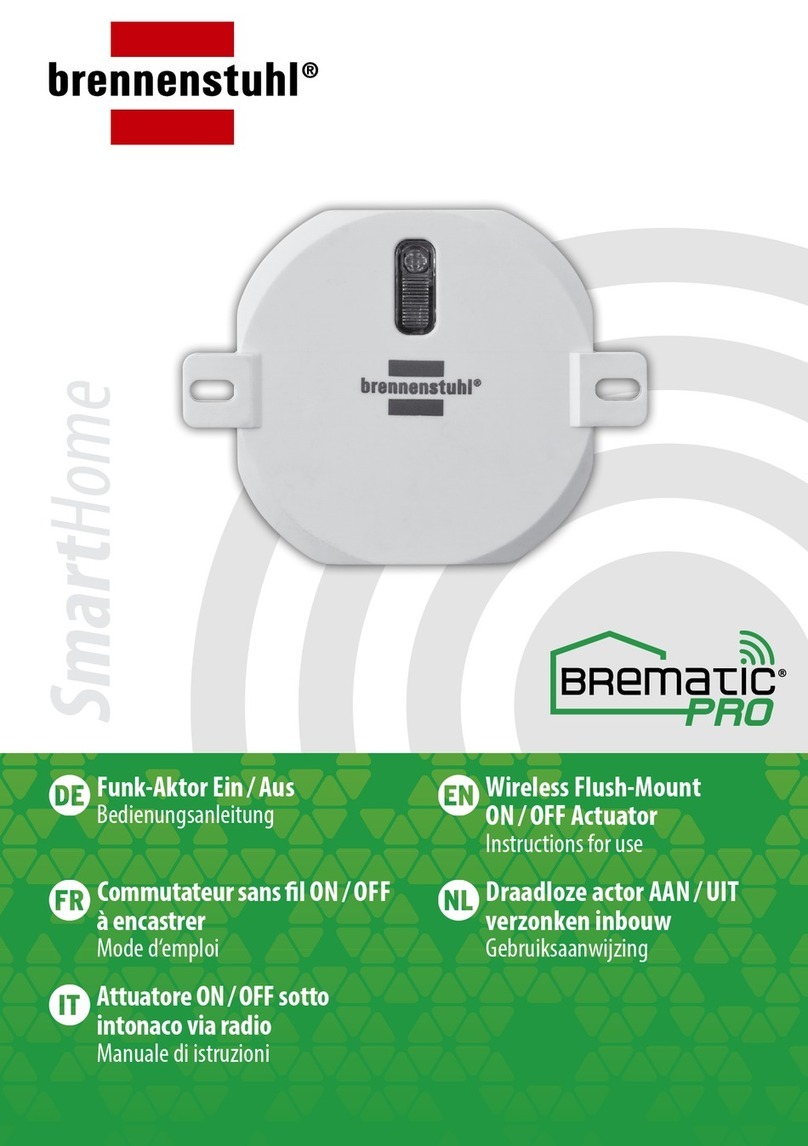
brennenstuhl
brennenstuhl BrematicPRO UPWS 868 01 W1000 3726 Instructions for use
Denso
Denso SMT7 instruction manual
UTC Fire and Security
UTC Fire and Security DET-TRONICS 95-8533 instructions
NEC
NEC NEC Express5800 Series user guide
Hunter
Hunter Hydrawise Pro-HC Connecting

LOVATO ELECTRIC
LOVATO ELECTRIC DCRL8 instruction manual
