DeDietrich M 300 S User manual

English
M 300 S
Fuel oil burner
EN
Installation instructions
300003201-001 - F

M 300 S 11/2010 - 300003201-001 - F
Declaration of conformity CE
Declaration of compliance D.R. 17/07/2009 - BE
Manufacturer SPM SAS
2, avenue Josué Heilmann
Z.I. de Vieux-Thann
F - 68800 Vieux-Thann
;+ 33 3 89 83 63 00
+ 33 3 89 83 63 07
Issued by See end of notice
We hereby certify that the range of equipment specified below is in accordance with the format stated in the EC
declaration of comformity, that it is manufactured and distributed in accordance with the regulations and requirements
in european directives and with the regulations and requirements defined in the Royal Decree dated 17/07/2009:
Type of product Fuel oil burner
Model M 300 S
Applied standards - Royal Decree dated 17/07/2009
- BImSchV 2010
- Standard EN 267
- 2006/95/EC Low Voltage Directive
Reference Standard: EN 60.335
- 2004/108/EC Electromagnetic Compatibility Directive
Reference Standards: EN 55.014 - EN 61000
Inspecting organisation TÜV Rheinland / Berlin-Brandenburg
OB 372005 Z2 - 13/12/2005 OB 842005 Z3 - 13/12/2005
OB 1022005 Z2 - 13/12/2005 OB 852005 Z3 - 13/12/2005
OB 1382005 T1 - 18/11/2005 OB 862005 Z3 - 13/12/2005
OB 1292005 E2 - 18/11/2005
Measured values M 301-2 S: NOx = 138 mg/kWh ; CO = 8 mg/kWh
M 301-3 S: NOx = 138 mg/kWh ; CO = 8 mg/kWh
M 301-4 S: NOx = 132 mg/kWh ; CO = 6 mg/kWh
M 302-1 S: NOx = 134 mg/kWh ; CO = 39 mg/kWh
M 302-2 S: NOx = 170 mg/kWh ; CO = 12 mg/kWh
M 302-3 S: NOx = 141 mg/kWh ; CO = 4 mg/kWh
M 302-4 S: NOx = 143 mg/kWh ; CO = 4 mg/kWh
M 302-5 S: NOx = 144 mg/kWh ; CO = 7 mg/kWh
M 302-6 S: NOx = 146 mg/kWh ; CO = 14 mg/kWh
Date : 11/2009 Signature
Chairman
Mr Philippe WEITZ

Contents
M 300 S 11/2010 - 300003201-001 - F
Security Measures..................................................................................................................................................4
Important information ............................................................................................................................................4
Burner description..................................................................................................................................................5
1 Brief description......................................................................................................................................................................................5
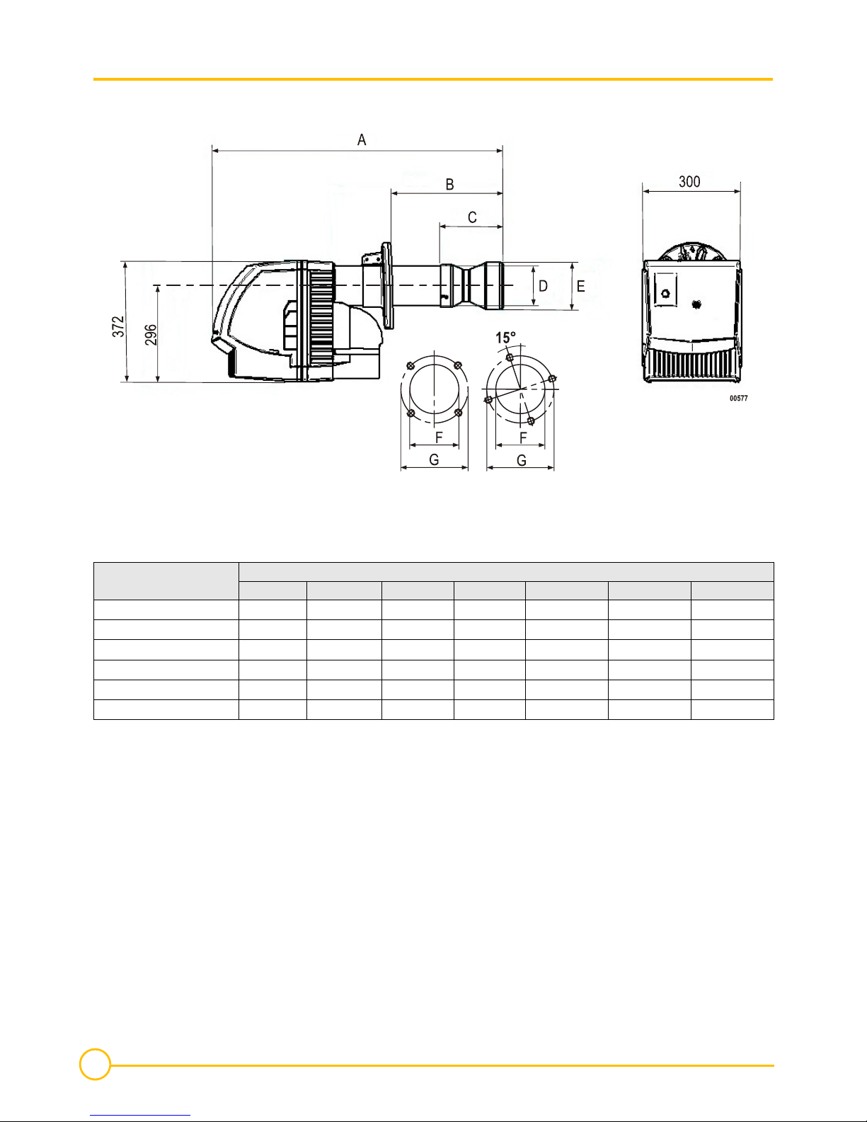
2 Dimensions.............................................................................................................................................................................................6
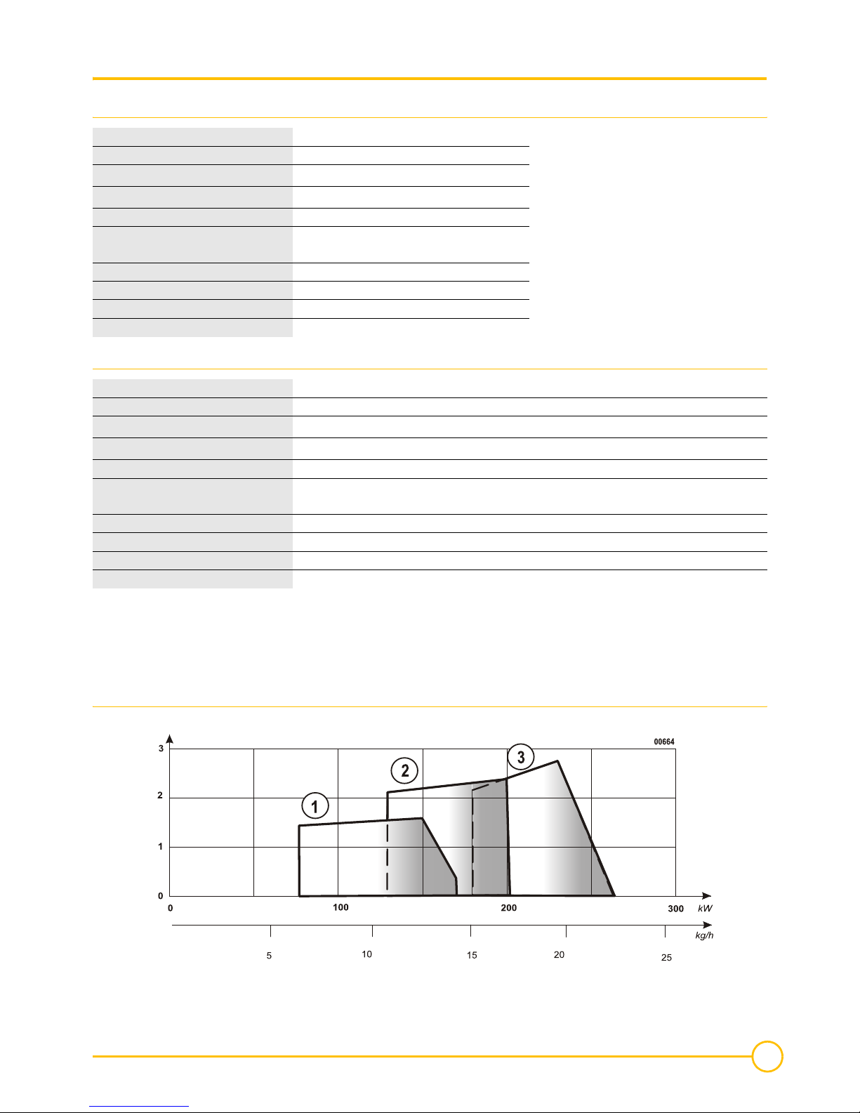
3 Technical data........................................................................................................................................................................................7
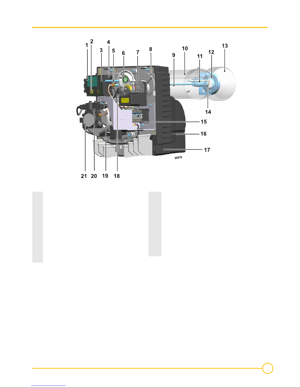
4 Main parts...............................................................................................................................................................................................9
5 Base with cables - Command and safety box ......................................................................................................................................13
Command and safety box ....................................................................................................................................14
1 Operating cycle ....................................................................................................................................................................................14
2 Safety (For DKO 976 only)...................................................................................................................................................................14
3 Diagnosing breakdowns (For DKO 976 only).......................................................................................................................................14
Installation.............................................................................................................................................................15
1 Assembly of the sliding flange..............................................................................................................................................................15
3 Maintenance.........................................................................................................................................................................................16
4 Fuel oil nozzle assembly ......................................................................................................................................................................17
5 Positioning the turbulator and ignition electrodes.................................................................................................................................17
6 Positioning the mechanism ..................................................................................................................................................................18
7 Fuel and electrical connections............................................................................................................................................................18
Adjustment............................................................................................................................................................19
1 Recommended Settings M 301 S.........................................................................................................................................................20
2 Recommended Settings M 302 S.........................................................................................................................................................22
Checking the operation........................................................................................................................................24
Final checks ..........................................................................................................................................................24
Maintenance procedure .......................................................................................................................................24
Electrical diagram.................................................................................................................................................25
Operating incidents..............................................................................................................................................27
Spare parts - M 300 S - 300003201-002-F............................................................................................................28

4
11/2010 - 300003201-001- F M 300 S
Security Measures
• Installation must be carried out in accordance with current laws.
• Current safety and accident prevention regulations must be respected at all times.
• Burner assembly, start up, operation and maintenance (inspection, servicing, repair) must be carried out by qualified, properly trained
personnel.
• Only the manufacturer is authorised to undertake repair work on the electrotechnical parts, flame detection devices and other safety
equipment.
• Changes and modifications not specified in this document and which may cause serious malfunction to the burner are prohibited..
•All work, except for adjusting the burner, shall only be carried out after the burner has stopped and after the power supply has
been disconnected.
• We shall not accept any responsibility for any damage and disturbance arising from not following these instructions !
The flame tube temperature is high. The baffle temperature is high. Handle with care.
Important information
Handing over the system to the user
• When the system is being handed over to the user, the installation engineer shall draw particular attention to the actions that the user is
authorised to carry out (when the burner is on safety for commissioning the system) and to the actions and modifications that may only be
undertaken by qualified personnel.
• The user must ensure that only a qualified professional has maintained the burner.
• This document is an integral part of the burner. Please keep it carefully in the furnace room near to the appliance.
Installation maintenance
To get the most out of your burner and to avoid operating difficulties, make a a qualified technician carries out the following:
• Cleaning the combustion head.
• Replacing the fuel oil nozzle.
• Replacing the electrodes (If necessary).
• Checking the burner's operation.
• Checking and cleaning the boiler.
• Checking and cleaning the chimney.
• Checking and cleaning the new air heater input.
For wearing parts, see the list of spare parts at the end of these instructions.
Used symbols
Caution danger !
Risk of injury and damage to equipment.
Attention must be paid to the warnings on safety of persons and equipment.
Specific information. Information must be kept in mind to maintain comfort.
, , Assembly stage
1, 2, 3Markers

5
M 300 S 11/2010 - 300003201-001 - F
Burner description
1 Brief description
M 300 S range burners are compact fuel burners which meet standards on burners with air flow adjustment :
• They are delivered with cables connected.
• They are assembled onto the furnace with a sliding clamp.
• All of the parts are assembled on an easily accessible plate.
• The plate containing the parts is located for optimal maintenance.
• The flame is checked using a photo-resistant cell.
• Ignition is by electronic transformer.
• Insulation class : IP 21
Envisaged use
M 300 S range burners are designed to specifically operate with "hot water furnaces" for heating premises and domestic hot water.
Please contact us for other applications, industrial processes and specific applications.
Check for optimal compatibility with the burner equipment / furnace / flue in order to guarantee a low pollution operation. The layout and size
of the flue shall be in accordance with the existing directives and regulations.

6
11/2010 - 300003201-001- F M 300 S
2 Dimensions
Dimensions (in mm)
Possible drill holes in the fire box door
Leave a minimum space of 1.00 m behind the burner, free of any obstacles to allow for maintenance.
Burner Side (mm)
A B C D E F G
M 302-1 S 635 100 Æ200 - 100 - 120 150 Æ170
M 301-2 S / M 302-2 S 687 140 Æ230 - 120 - min. 130 170 Æ220
M 301-3 S / M 302-3 S 710 140 Æ260 - 120 - min. 130 170 Æ220
M 301-4 S / M 302-4 S 725 140 Æ270 - 120 - min. 130 170 Æ220
M 302-5 S 755 140 Æ210 - 120 - min. 130 170 Æ220
M 302-6 S 882 190 Æ340 190 120 142 min. 130 170 Æ220

7
M 300 S 11/2010 - 300003201-001 - F
3 Technical data
M301S
M302S
(1) Power at an altitude of 400 m and at a temperature of 20°C. Calorific power of fuel oil: LHV = 11.86 kWh/kg
(2) Fuel: domestic fuel (max viscosity 6 mm²/s to 20°C).
* min. Stage1 / min. Stage2 - max Stage2
**Separate power supply (See Electrical diagram).
Power curves according to the EN 267 standard (1) - M 301 S
Fire box counter pressure (mbar)
Burner M 301-2 S M 301-3 S M 301-4 S
Operation 1 stage 1 stage 1 stage
Nominal output [kW] (1)*77 - 166 130 - 202 184 - 261
Fuel flow [Kg/h] (2)*6.5 - 14 11 - 17 15.5 - 22
Power consumption [W] 360 550 550
Nominal power of the motor [W] 260 W -
2850 tr.min-1
380 W -
2850 tr.min-1
380 W -
2850 tr.min-1
Sound level at 1 m [dBA] 69 70 70
Net weight [kg] 21 21 21
Gross weight [kg] 24 24 24
Turbulance generator mark 234
Burner M 302-1 S M 302-2 S M 302-3 S M 302-4 S M 302-5 S M 302-6 S
Operation 2 stages 2 stages 2 stages 2 stages 2 stages 2 stages
Nominal output [kW] (1)*75/98 - 142 80/113 - 160 94/181 - 217 142/192 - 275 126/202 - 430 114/179 - 460
Fuel flow [Kg/h] (2)*6.3/8.2 - 12 6.7/9.9 - 13.5 7.9/15.3 - 18.3 12.0/16.2 - 23.2 10.6/17 - 36.3 9.6/15.1 - 38.8
Power consumption [W] 360 360 550 550 1000 1000
Nominal power of the motor [W] 260 W -
2850 tr.min-1
260 W -
2850 tr.min-1
380 W -
2850 tr.min-1
380 W -
2850 tr.min-1
650 W** -
2850 tr.min-1
650 W** -
2850 tr.min-1
Sound level at 1 m [dBA] 68 69 70 70 72 73
Net weight [kg] 22 22 22 22 30 30
Gross weight [kg] 25 25 25 25 33 33
Turbulance generator mark 123455
G<H
M 301-2 S M 301-3 S M 301-4 S

8
11/2010 - 300003201-001- F M 300 S
Power curves according to the EN 267 standard (1) - M 302 S
Fire box counter pressure (mbar)
(1) Power at an altitude of 400 m and at a temperature of 20°C. Calorific power of fuel oil: LHV = 11.86 kWh/kg .
Standard EN 267 Standard EN 267
For Belgium
G<HIJK L
M 302-1 S M 302-2 S M 302-3 S M 302-4 S M 302-5 S M 302-6 S M 302-6 S

9
M 300 S 11/2010 - 300003201-001 - F
4 Main parts
1Command and safety box 12 Turbulence generator
2Reset button 13 Flame tube
3Command box socket 14 Filler
4Ignition transformer 15 Contactor
5Turbulence generator adjustment screw 16 Air enclosure
6Flame display record 17 Housing
7Servomotor 18 Flame detection cell
8Part plate 19 Motor
9Filling line 20 Solenoid valves
10 Intermediate tube 21 Fuel pump
11 Ignition electrode

10
11/2010 - 300003201-001- F M 300 S
Fuel pump
It is a self aspirating geared pump which turns to the right(seen from above) :
- Includes input filter and fuel pressure regulator.
- It is adjusted using a dual tube system but this may be changed to a single tube system.
Carefuly empty the fuel pump during start up.
The single tube system is illegal in some countries. Please check existing legislation.
M 301 S
M 302-1 S / M 302-2 S / M 302-3 S / M 302-4 S
M 302-5 S / M 302-6 S
1Nozzle output
2Manometer measurement socket (Pressure)
3Vacuum gauge measurement socket (Depression)
4Setting the pressure pump (Stage1)
5Setting the pressure pump (Stage2) *
6Fuel aspiration
7Fuel return
8Solenoid valve speed 1
9Solenoid valve speed 2 *
* For M 302 S only
1Nozzle output
2Manometer measurement socket (Pressure)
3Vacuum gauge measurement socket (Depression)
4Setting the pressure pump (Stage1)
5Setting the pressure pump (Stage2)
6Fuel aspiration
7Fuel return + Internal diversion plug
8Solenoid valve speed 2
9Solenoid valve speed 1
Burner Pump type
M 301-2 S DANFOSS BFP 21 R3
M301-3S/M301-4S DANFOSS BFP 21 R5
M 302-1 S DANFOSS BFP 52 R3
M 302-2 S / M 302-3 S / M 302-4 S DANFOSS BFP 52 R5
M302-5S/M302-6S SUNTEC AT 265
Pump type BFP 21 R3 BFP 21 R5 BFP 52 R3 BFP 52 R5 AT 265
Ambient temperature (under the cover) 60°C 60°C 60°C 60°C max 70 °C
Manufacturer's pressure margin 7 - 20 bar 7 - 20 bar 7 - 25 bar 7 - 25 bar 8 - 25 bar
Max depression 0.45 bar 0.45 bar 0.45 bar 0.45 bar 0.45 bar
Max input pressure 2 bar 2 bar 2 bar 2 bar 2 bar
Max pump air flow at 10 bar 24 l/h 42 l/h 24 l/h 42 l/h -
Max pump air flow at 25 bar ---- 65 l/h

11
M 300 S 11/2010 - 300003201-001 - F
Hydraulic diagram - M 301 S
Hydraulic diagram - M 302 S
1Stop cock
2Fuel aspiration
3Fuel return
4Pump
5Setting the pressure pump Stage1
6Solenoid valve (Closed no voltage)
7Filler
1Stop cock
2Fuel aspiration
3Fuel return
4Pump
5Setting the pressure pump Stage1
6Setting the pressure pump Stage2
7Solenoid valve (Closed no voltage)
8Solenoid valve (Open no voltage)
9Filler

12
11/2010 - 300003201-001- F M 300 S
Air shutter servomotor - M 302-1 S / M 302-2 S / M 302-3 S / M 302-4 S
Set cam MV between ST1 and ST2 (5° below ST2).
Air setting servomotor - M 302-5 S / M 302-6 S
The servomotor drives the cams opening the air shutter.
To regulate the opening of the air shutter, use the ST1 cams for min. speed and ST2 for max speed.
Set cam MV between ST1 and ST2 (5° below ST2). Set cam ST0 to 0°.
For fine adjustment, use screws located on cams.
The servomotor ensures the following:
1CamST1Setting the air flow (Stage1)
2CamST2Setting the air flow (Stage2)
3CamMVElectro-valve opening (Stage2)
ABurner start up
A-B Preventilation
B-C Ignition
CPassage in 2 speed
C-D Regulation
DBurner stop
1CamMVElectro-valve opening (Stage2)
2CamST0Closing air shutter (No air flow)
3CamST2Setting the air flow (Stage2)
4CamST1Setting the air flow (Stage1)
ABurner start up
A-B Preventilation
B-C Ignition
CPassage in 2 speed
C-D Regulation
DBurner stop

13
M 300 S 11/2010 - 300003201-001 - F
5 Base with cables - Command and safety box
The base is a safety device and must not be opened.
1Servomotor connection cable
(For M 302 S only)
2Flame detection cell connection
3Burner to furnace connector (4 pole connector)
(For M 302 S only)
4Electro-valve connection (Stage1)
5Electro-valve connection (Stage2)
(For M 302 S only)
6Contactor connection (2 pole connector)
(For M 302-5 S - M 302-6 S only)
7Burner to furnace connector (7 pole connector)
8Green LED
Ignited Burner ignited
Off Burner off
9Earth connection to the parts plate

14
11/2010 - 300003201-001- F M 300 S
Command and safety box
The command and safety box is a safety device which must only be stacked on the base or removed when the current has been
switched off by the main heating installation switch. The command and safety box is a safety device which must not be opened.
1 Operating cycle
TF 874 - M 301 S
DKO 976 - M 302 S
2 Safety (For DKO 976 only)
The DKO 976 command box is operated by a microprocessor.
In the event of a disturbance, the LED is lit for 10 seconds, then the signal is switched off by a disturbance code, indicating the nature of the
fault. Breakdown diagnoses are indicated in the table below.
Malfunction description code
3 Diagnosing breakdowns (For DKO 976 only)
SATROPEN is a pocket terminal displaying disturbances and the intensity of the flame signal. It is available as an option.
FFlame detection
ZIgnition
MBurner motor
FT* Unblocking the fuel heater
VSolenoid valve
OV* Fuel pre-heater
SA External breakdown indicator
ta* Fuel heater reheating time: 55 70 s
tv Pre-ignition and preventilation time: 12 s
ts Safety time: 10 s
tn Post-ignition time: 20 s
* except M 301 S/M 302 S
FFlame detection
ZIgnition
MBurner motor
V1 Solenoid valve speed 1
V2 Solenoid valve speed 2
SA External breakdown indicator
tv1 Pre-ignition and preventilation time: 15s
tv2 Speed timer 2: 20s
ts Safety time: 5s
tn Post-ignition time: 7s
tf Surveillance time for flare: 5s
Short press Long press .Short pause -- Long pause
Error code Type of fault Cause of fault
Disturbance occurrance while in safety time No flame detection
Unwanted light during preventilation Unwanted light
Cell defective
-- Manual or external disturbance External fault

15
M 300 S 11/2010 - 300003201-001 - F
Installation
Recommendations on electricity connection
A manually controlled sectioning device must be used to insulate the installation during maintenance, cleaning and repair work.
At the same time all non earthed conductors must be cut. This switch is not supplied. The burner is manufactured to operate in
a 230V - 50Hz single phase system.
This burner does not require a thermal relay to be attached. A 10 AT fuse is required for separate power supply.
Provide a separate power supply for the M 302-5 S - M 302-6 S burner.
Prior to any action on the burner, it has to be disconnected from the electricity supply. Installation and electrical connections
are to be made in accordance with existing regulations. Check that the earth is properly connected.
The connection cables supplied are certified under DIN 4791.
Recommendations for fuel connection
The burner is supplied with dual tube fuel connection: an aspiration pipe and another for the return to the tank.
It is possible to connect a single tube from the filter : It is not advisable to use a single tube connection between the filter and the burner's pump.
A filter must be attached (mesh size between 80 µm and 150 µm) in the fuel aspiration to avoid dirt deposits in the nozzle.
1 Assembly of the sliding flange
Assemble the gasket and the sliding clamp onto the furnace keeping to the direction marked 1.
Tighten the screws .

16
11/2010 - 300003201-001- F M 300 S
2 Burner location
Unscrew the 3 screws 1.
Remove flame tube. Tighten screw 2.
Push the burner towards the back through the furnace door.
Assemble the flame pipe onto the intermediate pipe.
!Push the burner into the fire box so that the flame moves past the interior insulation of the fire box door by 160 mm (For M 302-6 S only).
"Press the burner into the hearth door so that the turbulator exceeds the 10-15 mm insulation inside the hearth door (M 301 S - M 302-
1 S - M 302-2 S - M 302-3 S - M 302-4 S - M 302-5 S).
#Fill in the resulting gap between the intermediate tube and the fire box door with insulating, fireproof material.
$Untighten screw 2.
%Tighten the sliding clamp screws.
3 Maintenance
Disconnect the electrical connection connectors.
Unscrew the 5 rapid action screws.
Extract the parts plate from the housing.
Position the component holder plate on the studs on the casing.
Avoid any mechanical force on the turbine. Do not use the turbine as a support point in order to stop it from turning.

17
M 300 S 11/2010 - 300003201-001 - F
4 Fuel oil nozzle assembly
Disconnect the ignition electrode cables.
Untighten screw 2. Remove the turbulator.
Check the capacity of the nozzle in terms of the required furnace power and its performance.
Tighten the nozzle.
!Position the turbulator. Tighten screw 2.
"Connect the ignition electrode cables.
5 Positioning the turbulator and ignition electrodes
Ignition electrodes
* Remove a 1 mm ring (For 60° fillers).
Check the sides indicated below.
To change the position the ignition electrodes, unblock them using the tightening screw 5.
Place the ignition cable around the nozzle line. Connect the ignition electrode cables.
Be careful not to mask the flame detector to avoid any problems with flame checking.
Filler Number of
rings =
Side (mm)
1 2 3 4
M 302-1 S 45° 2 5 4 4 5
M 301-2 S / M 302-2 S 45° 2 6 4 4 5
M 301-3 S / M 302-3 S 45° 2 6 4 4 5
M 301-4 S / M 302-4 S 45° 2 7 4 4 5
M 302-5 S 45° 2 7 6 5 5
M302-6S 60°* 1 7* 6* 5* 4*
45°28664

18
11/2010 - 300003201-001- F M 300 S
6 Positioning the mechanism
Carefully place the fuel oil line into the flame tube.
Attach the parts plate onto the housing.
Tighten the 5 quick tightening screws.
7 Fuel and electrical connections
Connect the burner pipes to the fuel installation.
Connect the electrical connectors.
For safety reasons, do not connect the fuel until start up !

19
M 300 S 11/2010 - 300003201-001 - F
Adjustment
Recommendations for measuring combustion
Fine tune the burner so that it meets the existing local regulations.
It is important that the flow of combustion products between the chimney and the furnace nozzle is sealed in order to avoid measurement errors.
In order to measure combustion, Keep to the burner's operating times:
- 10 min operation (Boiler at temperature),
- 20 min operation (Cold boiler).
After assembling and setting the burner:
- Check the soot index,
- Check the smoke gas emission values.
Keep to the advised settings to avoid having flame surveillance problems at low powers.
Sound optimisation (For M302-5S/M302-6Sonly)
The diagram shows the air chamber interior.
Place the cap in accordance with the required power. Attach cap.
Burner Maximum output
(kW) Position (Cap) Sound gain
M 302-5 S 210 2 dBA
M 302-6 S 170 2 dBA
M 302-5 S 315 1.7 dBA
M 302-6 S 265 2 dBA
Factory setting
M 302-5 S 410 1 dBA
M 302-6 S 385 1 dBA

20
11/2010 - 300003201-001- F M 300 S
1 Recommended Settings M 301 S
In grey: factory setting.
Burner
Burner power
[kW]
Nozzle
Danfoss
[GPH]
Fuel oil
pressure
[bar]
Air setting
(Distribution bar
3)
Indicative setting for
the head position
(Distribution bar 2)
(mm)
Size 6
(mm)
Value CO2
(%)
M301-2S
80 1.65 / 45° S 13.5 12 33 54
12.5
100 2.00 / 45° S 13.5 15 30 51
120 2.50 / 45° S 12.5 20 28 49
140 3.00 / 45° S 11.0 26 25 46
160 3.50 / 45° S 11.5 33 24 45
M301-3S
140 3.00 / 45° S 11.5 17 26 41
160 3.50 / 45° S 12.0 20 25 40
180 4.00 / 45° S 12.0 24 23 38
200 4.50 / 45° S 11.0 29 21 36
M301-4S
180 4.00 / 45° S 12.5 19 26 55
200 4.50 / 45° S 11.0 23 25 54
240 5.00 / 45° S 13.5 33 20 49
260 5.50 / 45° S 12.5 43 18 47
Table of contents
Other DeDietrich Burner manuals
Popular Burner manuals by other brands

Bentone
Bentone Pro 450i M Installation and maintenance instruction

Riello
Riello RS 70 VA Installation, use and maintenance instructions

Pelltech
Pelltech PV 180a user manual

Unigas
Unigas R91A Manual of installation - use - maintenance

COMPANION
COMPANION RB20 instruction manual

Beckett
Beckett SDC 24 VDC user manual

Capital
Capital Performance Series PSQSB2000 Use and care guide

elco
elco VECTRON ECO 1.34 operating instructions

Kettler
Kettler NEO 6 Assembly, operation & maintenance instructions

artisan
artisan ARTP-PB Care & use manual

Riello
Riello RLS 120/E FGR Installation, use and maintenance instructions

Summerset
Summerset TRLPB2 Installation instructions & owner's manual