Dee Moz CRO8 User manual
U S E R ’ S MAN UA L
1
! IMPORTANT !
If a symbol appears at the end of a
paragraph, please comply with the
guidance!
CAUTION
Ensure you do not cut any pipes or high power
wires hidden behind your walls!
NOTE
The speakers’ grills can be lightly spray painted
to better match décor. Ensure grill perforations
are not affected during application.
NOTE
Carefully select speaker and wire location prior
to cutting holes. Avoid placing speaker wires near
home electrical wires.
32
To mount your speaker, you need the following items
(not supplied, available at your local electronics stores).
•Drywall or keyhole saw
•Wire stripper
•Phillips screwdriver
•Pencil
•Speaker wire
1. Be sure the mounting surface is between 0.37” (9.5mm) and 1.22” (31mm)
thick, with at least a 3.46” (88 mm) (CR065) or 3.71” (94.2 mm) (CR08) clearance
behind the mounting surface and no wall studs or other objects to block the
back of the speaker.
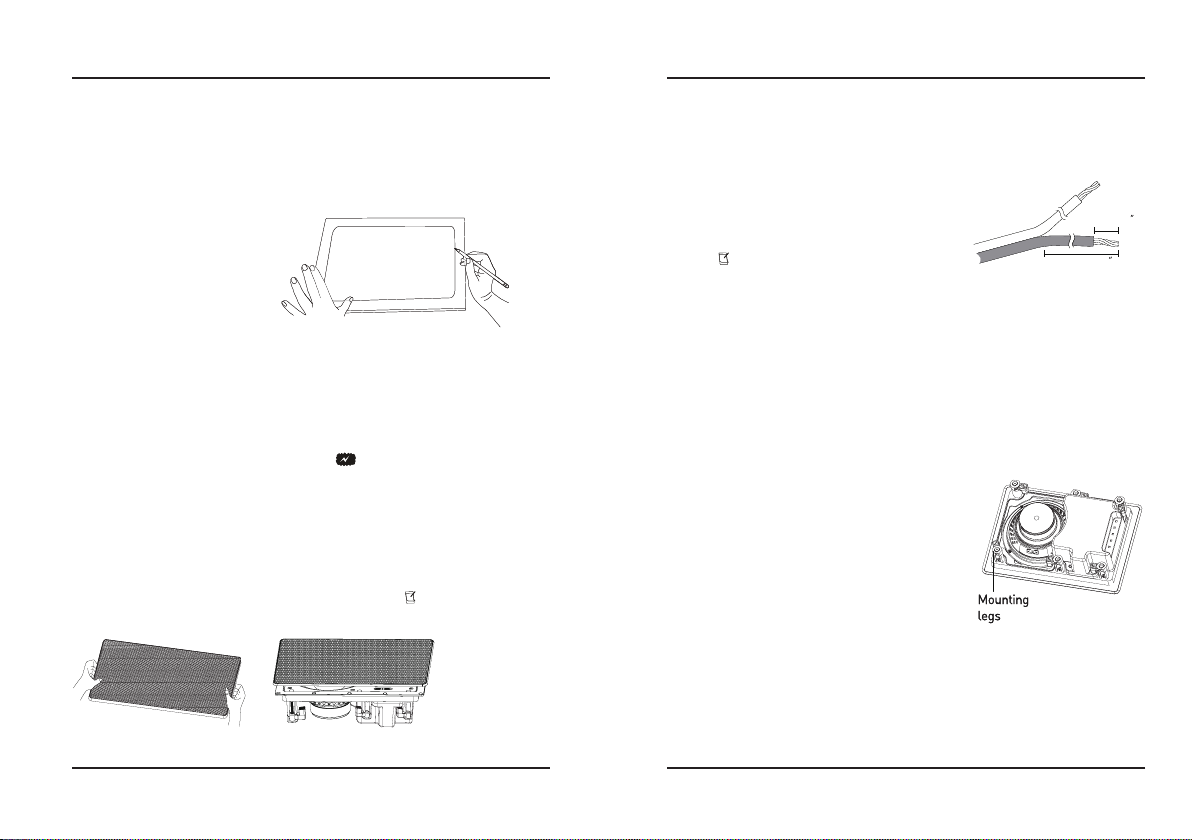
2. The provided speaker cut-out template opens to the actual hole size. Use this
template to help choose suitable locations for all speakers. Keep for future use.
3. Use a drywall or keyhole saw to cut the hole.
We suggest you use color or coding to mark the
speaker wires for correctly connecting the positive
and negative poles of the speaker.
1. Route the speaker wire to the speaker from the
receiver.
2. Separate about 3.98” (101 mm) of speaker wire at
each end.
3. Using a wire stripper, remove about 0.24” (6 mm)
of insulation from each wire. Then twist the ends of
each wire.
4. Press the red terminal, insert the marked positive
wire into the hole, then release the terminal,repeat
this step, then connect the wire marked negative to
the black terminal.
6mm (0.24 )
101mm (3.98 )
PREPARING THE LOCATION
lf you choose to paint the frame and grille, paint them and let them dry before
you connect the speaker wire or mount the speaker. To avoid affecting the
speaker’s acoustic performance, please make sure to remove the grille from the
speaker and paint the grille separately. Also, carefully remove the dust cloth
from the rear of grill and replace it after you finish painting.
PAINTING THE SPEAKER (OPTIONAL)
CONNECTING THE SPEAKER
WIRES
1. Remove the grille to expose the mounting screws.
2. Make sure the mounting legs are swung in, put
the speaker into the excavated hole, and then tighten
the screws.
3. Make sure the speaker is fixed in place on a wall
or ceiling. Be careful not to over tighten the screws.
Replace the grille.
INSTALLING THE SPEAKER
Remove the grille and loosen the screws only far
enough to remove the speaker. Be careful not to lose
the mounting legs.
REMOVING THE SPEAKER
32
To mount your speaker, you need the following items
(not supplied, available at your local electronics stores).
•Drywall or keyhole saw
•Wire stripper
•Phillips screwdriver
•Pencil
•Speaker wire
1. Be sure the mounting surface is between 0.37” (9.5mm) and 1.22” (31mm)
thick, with at least a 3.46” (88 mm) (CR065) or 3.71” (94.2 mm) (CR08) clearance
behind the mounting surface and no wall studs or other objects to block the
back of the speaker.
2. The provided speaker cut-out template opens to the actual hole size. Use this
template to help choose suitable locations for all speakers. Keep for future use.
3. Use a drywall or keyhole saw to cut the hole.
We suggest you use color or coding to mark the
speaker wires for correctly connecting the positive
and negative poles of the speaker.
1. Route the speaker wire to the speaker from the
receiver.
2. Separate about 3.98” (101 mm) of speaker wire at
each end.
3. Using a wire stripper, remove about 0.24” (6 mm)
of insulation from each wire. Then twist the ends of
each wire.
4. Press the red terminal, insert the marked positive
wire into the hole, then release the terminal,repeat
this step, then connect the wire marked negative to
the black terminal.
6mm (0.24 )
101mm (3.98 )
PREPARING THE LOCATION
lf you choose to paint the frame and grille, paint them and let them dry before
you connect the speaker wire or mount the speaker. To avoid affecting the
speaker’s acoustic performance, please make sure to remove the grille from the
speaker and paint the grille separately. Also, carefully remove the dust cloth
from the rear of grill and replace it after you finish painting.
PAINTING THE SPEAKER (OPTIONAL)
CONNECTING THE SPEAKER
WIRES
1. Remove the grille to expose the mounting screws.
2. Make sure the mounting legs are swung in, put
the speaker into the excavated hole, and then tighten
the screws.
3. Make sure the speaker is fixed in place on a wall
or ceiling. Be careful not to over tighten the screws.
Replace the grille.
INSTALLING THE SPEAKER
Remove the grille and loosen the screws only far
enough to remove the speaker. Be careful not to lose
the mounting legs.
REMOVING THE SPEAKER
4
Model CR065
Design 2-way
Tweeter 1 x Φ25 mm Ti and silk dome tweeter
Midrange/woofer 1 x 6.5” Fiberglass woofer
Sensitivity 87 dB ± 3 dB
Maximum power 100 W
Impedance 8 ohm
Recommended amplifier power 50 W
Frequency range 60 - 20K Hz
Special application High frequency controller +3/0/-3 dB
Dimensions (height x width x depth) 308.2 x 222 x 93.5 mm
Mounting Dimensions (height x width x depth) 274 x 188 x 88 mm
Net weight 2.1KG
SPECIFICATION
DeeMoz warrants this product to be free from failures in materials and
workmanship for a period of one year from the date of purchase. During
the warranty period, DeeMoz (DM) will exercise responsibility to repair
or replace the product or any defective parts.
Should warranty service be required, please contact an authorized DM
dealer with proof of purchase in the form of a bill of sale or receipted
invoice, showing this product is within the warranty period.
This warranty is invalid if (a) the factory-applied serial number has
been altered or removed from this product; (b) the damage is caused
by improper operation, maintenance or installation; (c) the product has
been repaired by anyone other than DM or authorized repair-centers.
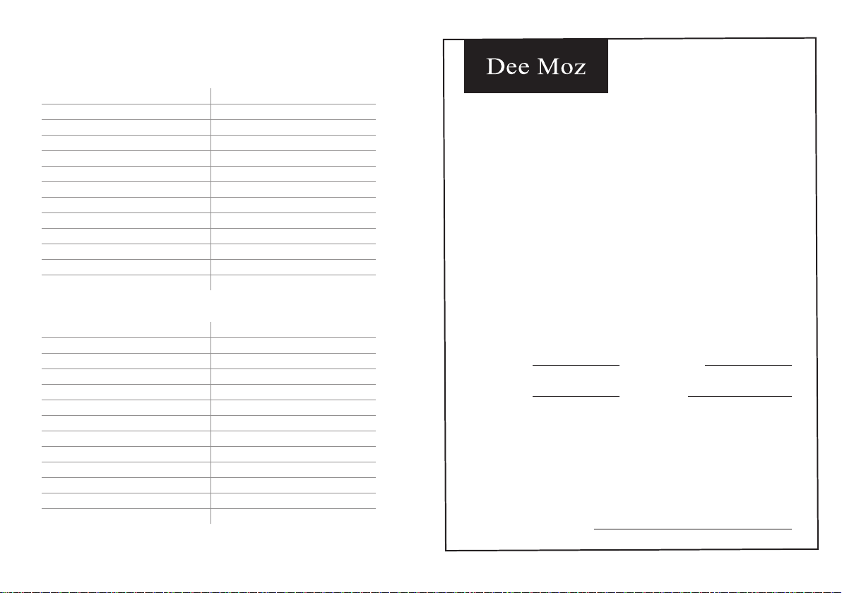
WARRANTY CARD
Serial Number Date of Purchase
Product Model Product Type
Dealer Stamp and Signature
Model CR08
Design 2-way
Tweeter 1 x Φ25 mm Ti and silk dome tweeter
Midrange/woofer 1 x 8” Fiberglass woofer
Sensitivity 88 dB ± 3 dB
Maximum power 140 W
Impedance 8 ohm
Recommended amplifier power 70 W
Frequency range 50 - 20K Hz
Special application High frequency controller +3/0/-3 dB
Dimensions (height x width x depth) 360.9 x 258.4 x 100.5 mm
Mounting Dimensions (height x width x depth) 327 x 225 x 94.2 mm
Net weight 3.0KG
This manual suits for next models
1
Other Dee Moz Speakers manuals


