DeepTech Vista SMART User manual

Instruction Manual
Vista SMART
Design – Silviya Rashkova &Plamen Rashkov
www.deeptech-bg.com

CONGRADULATIONS ON PURCHASING
YOUR VISTA SMART
Contents
1. Assembly
2. Controls explained
3. How to Ground Balance
4. Tips: How to set t e Vista SMART
5. Troubles ooting
6. Tec nical Specifications
7. General Advice
8. Limited Warranty Information
DeepTech is always interested in customer opinions. If you should
have any questions or comments regarding your Vista SMART or any
other DeepTech product, feel free to contact us directly or through
your local Authorized DeepTech dealer.
For further product information refer to:
www.deeptech-bg.com
2

DeepTech encourages all users to read the entire manual to ensure a
complete understanding of all the features and functions that your
Vista SMART offers.
Assembly
Before assembling your Vista Smart please check that the package includes the following
parts:
11” Wide scan coil (not to be submerged in water, the coil is water resistant only)
Lower shaft
Middle shaft with camlocks
Upper shaft
Fully assembled with:
- Control box
- Battery compartment with armrest and detector stand
- Padded hand grip
Coil hardware consisting of:
-Rubber washers (2)
-Plastic wing nut
-Plastic bolt
Velcro tabs (1)
Eight 1,5V AA Alkaline Batteries
DVD with the manual and product videos
Limited Warranty Information (in the instruction manual)
Instruction manual (you’re reading it )
If any of the above listed items are missing, please contact us immediately.
3
Assemble
4
11” coil
with
coil
hardware
Lower
shaft
assembly
Middle
shaft
with
camlocks
Upper pole assembly
with control box
Padded grip
Arm cup
with strap
Battery box
with sliding
door for the
battery
compartment

1.1 Connecting the coil to the lower shaft
Place t e two rubber was ers into t e oles on eit er side of t e lower s aft.
Slide t e bottom of t e lower s aft into t e bracket on top of t e coil. Make sure t at t e
spring loaded pin in t e lower s aft is pointed downwards.
Insert t e plastic bolt t roug t e ole in t e coil and t e lower s aft.
Fasten t e bolt wit t e plastic wing nut. Be careful not to damage t e t read of t e bolt by
over-tig tening. T e plastic wing nut may need to be loosened to adjust t e coil.
1.2 Shaft assembly
Make sure t at t e camlocks of t e middle s aft are loosened by rotating t em counter-
clockwise.
Pus in t e spring loaded pin on t e lower s aft and slide it into t e middle s aft until t e
pin reac es t e desired adjustment ole. Tig ten t e camlock by rotating it clockwise until
tig t. Remember not to over tig ten.
Attac t e upper s aft assembly to t e middle s aft by pus ing t e spring loaded pin in t e
upper s aft assembly and slide it into t e middle s aft until t e pin reac es t e adjustment
ole. Tig ten t e camlock by rotating it clockwise until tig t. Remember not to over
tig ten.
- Remember, t e detector s ould be set to lengt so t at it is straig t wit your forearm
and feels comfortable and lig t w en you pick it up.
1.3 Coil cable
Wind t e coil cable around t e complete s aft assembly enoug times to take up any slack.
Use t e Velcro strap to keep t e coil cable in place.
Carefully pus t e coil plug into t e socket on t e back of t e control box. Firmly tig ten
t e retaining ring by and to old it in place (do not over tig ten).
WARNING! T e cable coming from t e coil s ould not be wrapped to tig tly in t e coil area.
Leave enoug slack in t e cable so you can adjust t e coil w en you detect on uneven ground.
Failing to do t is may result in damage to t e coil cable or t e coil itself.
5

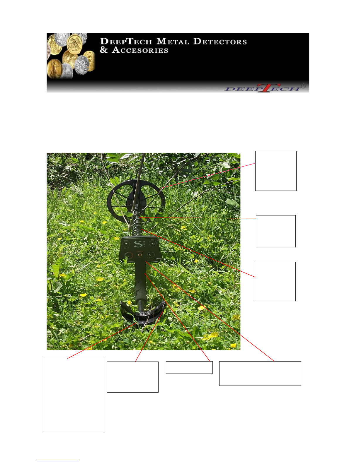
Controls
6
VOLUME
KNOB
LED INDICATOR
FOR
BATTERY LIFE
GROUND
BALANCE
SENSITIVITY
KNOB
DISCRIMINATIO
N
KNOB
BOOSTER
ON/OFF
TRIGGER
SEARCHMODE TRIGGER:
SILENT DISCRIMINATION
ALL METAL
2-TONE DISCRIMINATION
PINPOINT
BUTTON
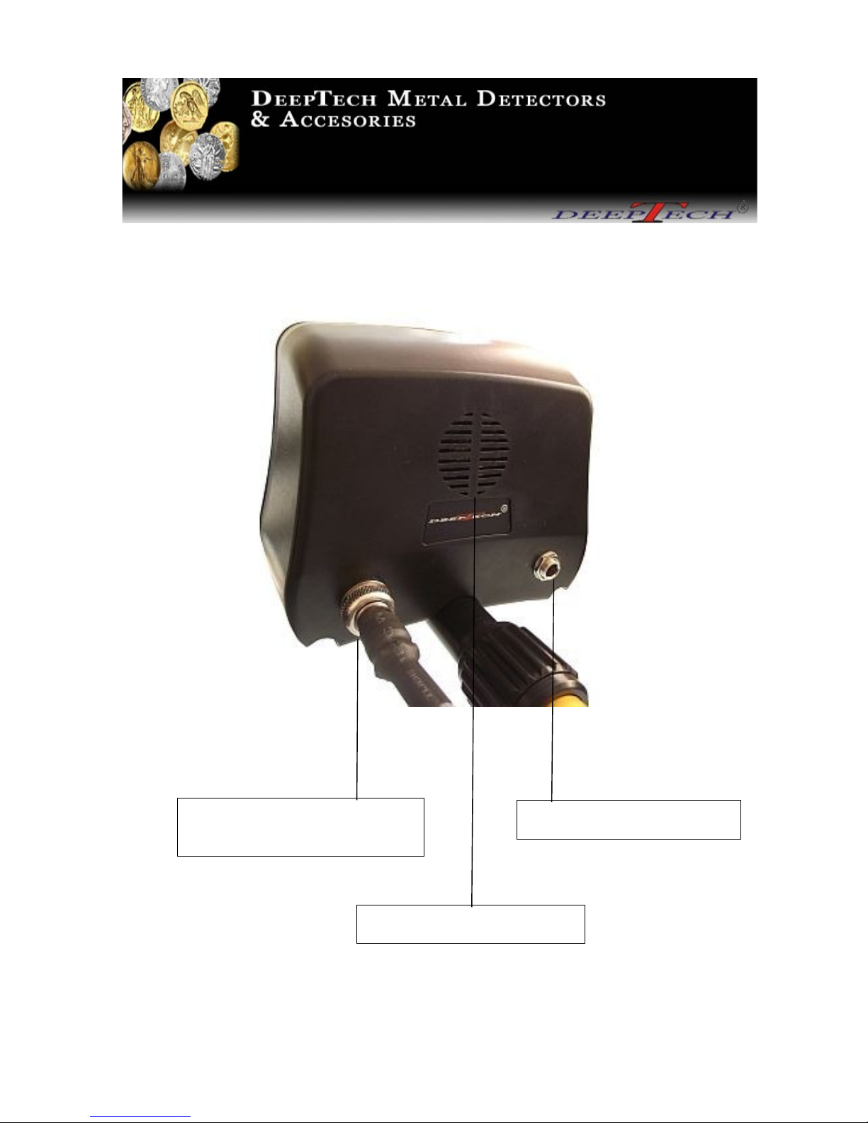
Rear view of the control box
7
HEADPHONE JACK
COIL PLUG
CONNECTOR
SPEAKER
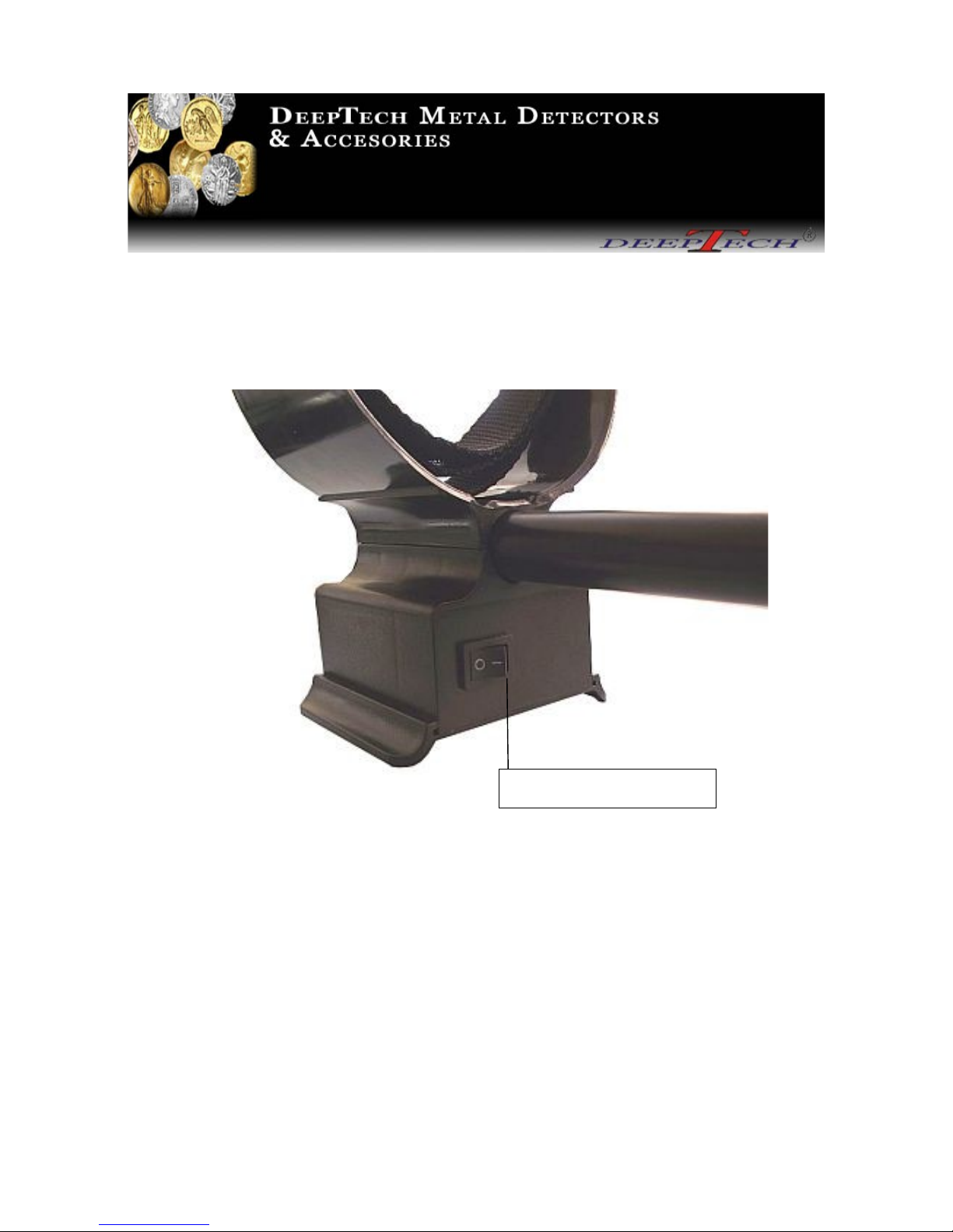
2.1 Power switch
T e power switc is located on t e front side of t e battery box. T is switc is used to turn
t e Vista SMART on or off.
WARNING! Never remove t e coil cable from t e control box w ile t e Vista SMART is turned
on. T is may result in damage to t e electronics.
8
ON/OFF switch

2.2 Sensitivity
Sensitivity is t e level of response to a target. T e Vista SMART is ig ly sensitive and as a wide
adjustment range. Alt oug t e Vista SMART as an operating frequency of 15,5 kHz for a
smoot and quiet operation, it is very important to set t e Sensitivity level correctly according to t e
detecting conditions.
A ig Sensitivity setting enables t e detection of smaller and deeper targets. W en t e Sensitivity
is set to ig , t e Vista SMART may be affected by minerals in certain soils and signals from elec-
trical appliances. You may need to decrease t e Sensitivity to silence false signals or electrical in-
terference. T is will result in a more stable operation of t e Vista SMART.
Always c oose t e ig est stable Sensitivity setting to ensure best performance. T is is done by
turning t e Sensitivity knob to t e rig t until t e Vista SMART becomes unstable; t en reduce t e
Sensitivity by one or two settings until it is stable.
2.3 Ground
T e Ground knob is used to adjust t e Vista SMART to t e soil conditions and correct ground
effects encountered during detecting. Mineralization and “Hot Rocks” may cause false signals.
Ground balancing t e Vista SMART reduces false signals from ground mineralization; more
accurately rejects ferrous minerals or pottery containing iron oxides and enables targets to be eard
correctly. If t ere are “Hot rocks”, t ese can be elliminated by turning t e Ground knob to t e
rig t.
Learning ow to properly Ground balance will give you a an advantage over ot ers especially if
t ey are running t ere detectors in an auto ground balance mode.
2.4 Discrimination
T e Disc. knob is used to eliminate iron objects from detection. T e Discrimination as a very fine
adjustability range. T e furt er t e knob is turned to t e rig t in t e Disc. Mode (also known as t e
SILENT DISCRIMINATION MODE, t e trigger on t e bottom rig t side of t e control box pulled
towards you), t e bigger t e size of t e iron object will be t at is to be discriminated. In t e last
t ird section of t e Discrimination scale, small aluminum foil will also be rejected. In t e 2 Tone
Mode (trigger on t e bottom rig t side of t e control box pus ed furt est from you), t e Disc. knob
as a different function. It is t en used to allow you to adjust t e audio level of t e low tone for
iron targets.
9

2.5 Volume
T e Volume knob lets you adjust t e audio level of t e speaker and eadp ones.
2.6 Pinpoint
T e Pinpoint button, w en pressed, allows you to locate t e target under t e coil. T e Pinpoint
function may also be used as a non-motion All Metal mode.
2.7 Headphone Jack ¼”
DeepTec recommends t e use of eadp ones. W en eadp ones are plug in, t e speaker is
automatically deactivated.
T ere a many advantages to using eadp ones:
- Improves battery life.
- Prevents t e sounds from annoying bystanders.
- Allows you to ear subtle c anges in t e sound and faint signals from deep targets more
clearly.
WARNING! Set your eadp one volume prior to wear. Ensure t at t e eadp one volume does
not reac an extremely loud level. T is may increase t e risk of earing damage.
2.8 LED Battery Control
T ere is an indicator “Low Bat” on t e face plate of t e control box. If t e indicator lig ts up and
stays on, t e batteries are almost totally ex austed. At t is stage, stop detecting and replace t e
batteries. If t e indicator blinks w en a target is detected, t e batteries are low. In t is case, it is
best to replace t e batteries at t is time. T e average battery life is about 20-25 ours. Extremely
weak batteries may t e reason for false signals. DeepTec strongly recommends to use 8 x 1,5 V
AA Alkaline batteries. W en using rec argeable batteries, we strongly recommend using batteries
wit more t an 2000mA/H.
- Remember, t e power consumption increases w en searc ing wit t e Booster ON.
10

2.9 Mode Trigger: 2 Tone Mode/All Metal/Disc. Mode
T e Vista SMART as a t ree position Mode trigger switc comfortably located on t e bottom
rig t side of t e control box w ere it is easily accessible during detecting. T e t ree position Mode
trigger switc gives you t e option to c oose, and quickly switc , between different modes of
operation.
Disc. Mode or Silent Discrimination Mode
(Back position, trigger pulled towards you.)
W en working in t e Disc. Mode (Silent Discrimination Mode), ferrous targets will be
discriminated by using t e Disc. knob. You will ear a ig tone if t e target is non-ferrous. If t e
target is ferrous t ere is no sound or, depending on t e size and s ape of t e ferrous object, s ort
„cracks“. T e size of t e ferrous object t at is to be discriminated is increased as you turn t e Disc.
knob to t e rig t
11
THREE POSITION TRIGGER SWITCH
BACK POSITION
(Trigger pulled towards you.)
SILENT DISCRIMINATION MODE or DISC. Mode

All Metal Mode
(Trigger in t e middle position.)
Use t e All Metal Mode (Trigger in t e middle position) for maximum dept w ere soil conditions
allow. In t is position, you are detecting wit out any discrimination. All metal targets will sound
off wit a ig tone. We recommended using t is Mode only if you do not want any discrimination
or w ere only good targets are anticipated.
12
THREE POSITION TRIGGER SWITCH
(MIDDLE POSITION)
ALL METAL MODE

2 Tone Mode
- Low tone for ferrous objects and High tone for non-ferrous objects.
(Forward position, trigger pus ed from you.)
In t e 2 Tone Mode, all non-ferrous and ferrous targets w ic are accepted according to t e Disc.
knob setting (to t e rig t of t e Disc. setting), will give a ig tone. All targets rejected by t e
Disc. knob setting (to t e left of t e Disc. setting) will give a low tone. You can adjust t e size of
ferrous target to be accepted by eit er turning t e Disc. knob to t e left (t e smaller t e size of t e
ferrous target in order to give a low tone) or by turning t e Disc. knob to t e rig t (t e bigger t e
size of t e ferrous target in order to give a ig tone). Big ferrous targets will still give a ig tone
but are easily identified by t e strong signal along wit a slig t low iron tone at t e end of t e
target.
T is Mode is ig ly effective in iron patc es to clearly identify non-ferrous targets among ferrous
targets and also to specifically searc for certain ferrous targets.
- Remember, t e Vista SMART must be properly ground balanced in t e 2 Tone Mode for
optimum performance.
13
THREE POSITION TRIGGER SWITCH
FORWARD POSITION
(Trigger pushed furthest from you.)
2-TONE MODE

2.10 Booster Trigger
T e Vista SMART as a two position Booster trigger switc comfortably located on t e bottom left
side of t e control box w ere it is easily accessible during detecting. T e two position Boost trigger
switc allows you to turn t e Booster On (by pus ing t e trigger in t e forward position, furt est
from you) or Off (by pus ing t e trigger in t e back position, towards you). W en t e Booster is
activated, you can ac ieve a 10-20% increase in dept for small targets and a 30% increase in dept
for bigger targets. DeepTec recommends you work wit t e Booster Off on ig ly mineralized
ground. Please remember t ere will be a ig er power consumption w en t e Booster is active.
Booster on
(Trigger in forward position, furt est from you.)
14
TWO POSITION TRIGGER SWITCH
FORWARD POSITION
(Trigger furthest from you.)
BOOSTER ON

Booster Off
(Trigger in back position, towards you.)
15
TWO POSITION TRIGGER SWITCH
BACK POSITION
(Trigger towards you.)
BOOSTER OFF

How to Ground Balance
T e following steps will explain ow to Ground Balance t e Vista SMART. T is is a very simple
process t at allows you to balance t e Vista SMART to all types of soil. T is is very important in
order to obtain maximum sensitivity to small targets and dept .
Turn on t e Vista SMART wit t e Power Switc
Set t e Sensitivity as described in section 2.2 Controls/Sensitivity
Switc t e t ree Position Trigger Switc to t e 2 Tone Mode
Find an area free of metal targets
Turn t e Ground knob all t e way to t e left
Lower t e coil about 2 cm (1 inc ) above t e ground
Raise t e coil up about 15 cm ( 6 inc es)
Repeat t is process as you gradually turn t e Ground knob to t e rig t until t ere is no or very
little noise as you lower and raise t e coil
Set your desired level of Discrimination
Your Vista SMART is now Ground Balanced. If t e soil conditions c ange significantly (by
moving from a plowed field into a wooded area for instance), you must ground balance your Vista
SMART again as described above.
You may Ground Balance in t e Disc. Mode or All Metal Mode instead, but setting t e Ground
Balance in t e 2 Tone Mode is more precise. You can t en switc to w ic ever mode you c oose.
If you are receiving false signals from iron oxides in pottery or “Hot Rocks”, you can t en Ground
Balance t e Vista SMART directly over t ese objects to eliminate signals from t ese unwanted
targets.
.
16

Tips: How to set the Vista SMART
T ese tips will elp to s orten t e “learning curve” of t e Vista SMART.
If searc ing in t e DISC. Mode for coins and ot er non-ferrous targets on ig ly mineralized
ground t at also contain many iron patc es:
- Ground Balance t e Vista SMART as described in Section 3 How to Ground Balance
- Set t e DISC. knob between 20-30
- Set t e Sensitivity knob between 30 -35 ( you may set t is value ig er if you are not
receiving too muc “c atter”)
- Remember, fair amounts of iron in t e ground paired wit a low Disc. setting will result in
“c atter”. T is is avoided wit t e settings described above. If you feel t e Vista SMART
is still giving you too muc “c atter”, reduce t e Sensitivity instead of raising t e level of
Discrimination. If t e level of Discrimination is raised under t ese conditions, more time
will be needed to process t e signals t erefore increasing t e detection distance between t e
discriminated iron object and t e desired non-ferrous target in order for t e desired target to
be detected. Wit a little practice you will master t ese difficult conditions wit ease.
*T is may only appen in t e DISC. Mode. Remember, t e Vista SMART ast a very fast
recovery speed even wit a ig Discrimination setting and will outperform may ot er detectors.
If searc ing on ground wit “normal” mineralization and very few ferrous targets:
- Ground Balance t e Vista SMART as described in Section 3 How to Ground Balance
- Set t e Sensitivity as ig as possible
- Set t e Discrimination to your liking
T e 2 Tone Mode may be used in basically any situation. In t is Mode, t e Disc. knob as a
different function. It is t en used to allow you to adjust t e audio level of t e low tone for iron
targets. For example, if t e Discrimination is set to “0”, all ferrous targets will emit a ig tone.
T e furt er you turn t e Disc. knob to t e rig t, t e bigger t e ferrous target must be in order to
emit a ig tone. If you are searc ing for non-ferrous targets, it is recommended t at t e
Discrimination is set between 20-30. In t e 2 Tone Mode t e Vista SMART is extremely fast and
sensitive.
17

Troubleshooting
T e Vista SMART will not power on:
- Insert Batteries
- Replace Batteries
- Batteries installed incorrectly
- Battery pack not connected
Excessive false signals:
- Sensitivity too ig
- Incorrect Ground Balance
- Coil cable loose or not connected
T e Vista SMART is producing only long tones:
- Incorrect Ground Balance
- Very ig ground mineralization (repeat Ground Balance process on objects producing t ese
tones)
18

6. Technical Specifications
Operating
Frequency.............................................15,5 kHz
Detector typ.............................................................motion
Sensitivity control
Volume control
Manual Ground Balance
T ree Modes of operation:
- DISC. Mode
- 2 Tone Mode (low tone for ferrous objects and ig tone for non-ferrous objects)
- All Metal Mode
Recovery speed…………………………………...Very fast
Booster
Pinpoint
Searc coil
Type .....................................................2D
Searc coil Size........................................................11”
Cable Lengt (approx.)..........................................53” ( 135 cm )
Audio Frequency( approx.)...................................780/390 Hz
Weig t ( wit batteries )................... ....................(approx.)1400g.
Power Consumption ( Booster OFF )...................43 mA
Power Consumption ( Booster ON ).....................52 mA
Battery Requirement – we strongly recommend to use 8 x 1,5 V AA Alkaline Batteries or
rec argeable Batteries wit more t an 2000mA/
Battery Life (typical).............................................20-25 ours
LED Low Battery alert
Operation Temperature Range..............................10-40 C
Optimum Humidity............................................... 0 to 75% R.H.
19

7. General Advice
Metal Detecting is an activity, which like other leisure activities requires some guiding prin-
ciples. The following recommendations will allow you to fully enjoy your hobby while re-
specting laws, environment and other people.
Enquire about and abide by t e laws in force of t e country or t e state before
searc ing. It is your responsibility to know t em and to abide by t em.
Always ask permission of t e land owner w ere you want to searc .
Have respect for nature and t e environment in w ic you are searc ing.
Don’t forget to fill all oles you dig and properly dispose of any tras .
WARNING Avoid detecting in zones where battles took place during both World Wars.
Report any suspect object you might discover to the authorities.
Joining a Metal Detecting Club in your area is an easy way of enjoying
and s aring t is wonderful obby wit ot ers. T is is also an easy
start as ow to properly abide to t e et ics of Metal Detecting.
Since t is is only a guide, you are of course responsible for actions
on any property you decide to detect. Always leave t e area
neat and clean.
We would like to t ank you again for purc asing a DeepTec product.
S ould you ave furt er inquiries, feel free to contact us via
E-mail, fax or p one. We appreciate any comments or suggestions.
Leaving feedback and suggestions will elp to improve our products, if necessary,
for everyone to enjoy.
20
Table of contents
Other DeepTech Metal Detector manuals

DeepTech
DeepTech VISTA X User manual

DeepTech
DeepTech Vista RG 1000 V1 User manual

DeepTech
DeepTech DISCRIMINATOR User manual

DeepTech
DeepTech Vista MINI User manual

DeepTech
DeepTech VISTA X User manual

DeepTech
DeepTech Vista Series User manual

DeepTech
DeepTech Ground Pioneer 4500 User manual

DeepTech
DeepTech MEGAPULSE III User manual
Popular Metal Detector manuals by other brands


Steinberg Systems
Steinberg Systems SBS-MD-21 user manual

Hilti
Hilti PS 250 operating instructions

XP Metal Detectors
XP Metal Detectors GOLD MAXX Power instruction manual

Harbor Freight Tools
Harbor Freight Tools 62307 Owner's manual and safety instructions

Tesoro
Tesoro VAQUERO Operator's instruction manual

Fisher
Fisher F-Pulse owner's manual


